Abstract
A central venous catheter (CVC) should be inserted at the optimum position to infuse medicines, blood products, nutrients, or fluids. Positioning of the catheter tip is commonly performed under landmark or fluoroscopic guidance. However, Japanese regulations do not allow the performing of fluoroscopy-guided procedures outside of the fluoroscopy room. We hypothesized that a new image-guided CVC placement technique by combining a wireless flat-panel detector (FPD) and a mobile X-ray system could be applied at the bedside to support CVC insertion. A CVC attached to a chest phantom in conjunction with the polymethyl methacrylate (PMMA) phantom was imaged, contrast-to-noise ratio (CNR) was measured with images, and radiologists and emergency physicians rated the catheter images using a Likert scale for visual evaluation. The minimum dose of the FPD and mobile X-ray system was reduced by at least 98% compared with that of the X-ray fluoroscopy system. The CNR decreased with the increasing PMMA phantom thickness. However, results of the visual evaluation were maintained at the clinically usable score with low-dose imaging up to a 6-cm thickness of the PMMA phantom. In conclusion, the combination of FPD and mobile X-ray systems is particularly effective in the emergency room setting where such procedures are required to be performed with urgency.
Introduction
Forssmann developed the central venous catheter (CVC) in 19291), and Dudrick and Filler clinically introduced central venous hyperalimentation2,3) as an application of CVC implantation in the late 1960s. Nowadays, this method is used for short-term nutrition management4), perioperative management5), chemotherapy6), central venous pressure monitoring, and circulatory drug administration. This method is frequently used in clinical medicine, emergency medicine, and intensive care treatment due to its simplicity and usefulness. Successful CVC insertion is determined by anatomical markings on the body surface7), auscultation using saline flush8), contrast-enhanced ultrasonography using saline containing microbubbles9), and fluoroscopy-guided methods using an X-ray fluoroscopy system10). The fluoroscopy-guided method allows assessment of the entire process in real time, from determination of a puncture location to observation of catheter placement, prevention of straying into vessels other than the target vessel and cardiac tamponade11,12), and visualization of the dilator insertion process, thus, avoiding vascular damage and serious bleeding complications caused by the dilator. Previous studies reported that the combination of fluoroscopy- and ultrasound-guided methods allows the performance of a safe, reliable, and rapid procedure13). To perform fluoroscopy-guided methods, patients must be transferred to a fluoroscopy room, as per Japanese regulations. However, the risks associated with transferring a critically ill or emergency patient could be high.
In recent years, the flat-panel detector system (FPD) has become a well-known alternative to computed radiography, which uses phosphor imaging plates. The FPD enables the observation of acquired images within seconds after X-ray exposure. Next, images can be obtained without replacing the FPD, and multiple images can be obtained while the FPD is positioned with the patient. Spacing X-ray exposure using a mobile X-ray system and FPD may be a viable alternative to fluoroscopy. This method does not require patient transfer to the fluoroscopy room and enables easier image acquisition. Therefore, the implantation position of the CVC can be determined while checking its tip as an alternative to the fluoroscopy-guided method in the emergency and intensive care settings.
This study aimed to evaluate the clinical applicability of combining a mobile X-ray system and a wireless flat-panel detector system for low-dose image-guided CVC insertion, which we propose as a new technique.
Materials and methods
1.1 Equipment
The FPD system (AeroDR1717, Konica Minolta, Tokyo, Japan) combined with a mobile X-ray system (Optima XR220amx, GE Healthcare Japan, Hino, Japan) was used. This system can display acquired images on a dedicated laptop computer approximately 14 s after X-ray exposure. The low-dose mode (L mode) of the X-ray fluoroscopy system (EXAVISTA, Hitachi Medical, Kashiwa, Japan) was used as a reference for comparison. This system can store still images with the same quality as fluoroscopic images. In this study, these fluoroscopic records were used to assess the image quality. To measure the patient surface dose, the potentiometer (Model 9015, Radcal, California, USA) was used with an ionization chamber (10 × 6 - 6, Radcal, California, USA) with an ionization volume of 6 cc. The potentiometer and ionization chamber dosimeter were calibrated by the Japan Quality Assurance Organization. The chest phantom (PBU-X-21, Kyoto Science, Kyoto, Japan) used in this study is equivalent to that of the human body, i.e., chest thickness of 18.6 cm. Furthermore, a 40 × 40-cm polymethyl methacrylate (PMMA) phantom was used to adjust the chest thickness. This is often used as a human body equivalent phantom and has a density of 1.18 g/cm3 14). A CVC with an outer diameter of 2.5 mm (CV Legaforce EX, Terumo, Tokyo, Japan) was selected in this study.
1.2 Measurement of patient surface dose in chest phantoms
The patient surface dose was measured in two combinations: FPD with the mobile X-ray system and FPD with the X-ray fluoroscopy system. The PMMA phantom was placed on the chest phantom in 2 cm increments from 2 cm to 14 cm to differentiate differences in patient body thickness. The X-ray fluoroscopy system was performed with a focal spot-to-FPD distance of 120 cm and radiation field size of 42 × 42 cm, measurements commonly used in clinical practice. The mode recommended by combined parameters of the manufacture was set to the chest (kV step, 1 kV; mAs step, 1 mAs; fluoroscopy conditions, fully automatic mode; fluoroscopy auto gamma, 1; and brightness, 1). The mobile X-ray system was used at 0.2 mAs (low-dose FPD) regardless of PMMA phantom thickness. A 0.2 mAs is the minimum value of the system. The ion chamber was placed at the midline of the chest phantom at 10 cm from the bottom. The chest phantom was irradiated using an X-ray fluoroscopy system, and the patient surface dose rate (mGy/s) was measured by varying PMMA phantom thickness. Then, the patient surface dose (mGy) was measured using the mobile X-ray system (Fig. 1).

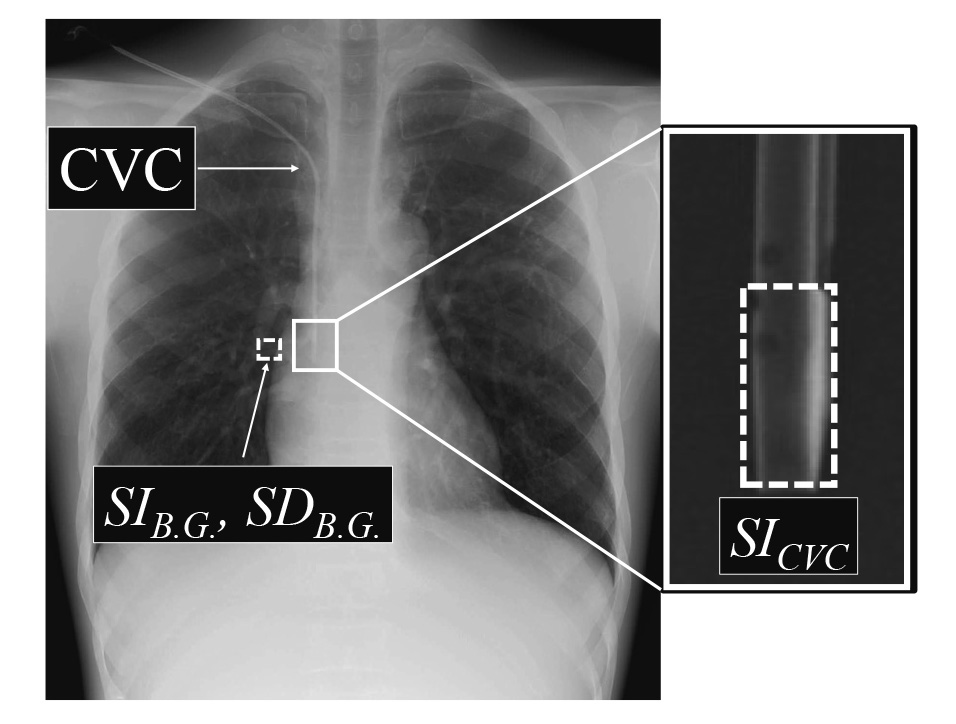
The CNR of a catheter tip was measured by combining the FPD and mobile X-ray system to evaluate the image quality and compared with that of the X-ray fluoroscopy system. The image was obtained using the geometric arrangement described in Methods 1.2. Three images of fluoroscopic recordings using the X-ray fluoroscopy system were saved 10 s after starting the fluoroscopy procedure. Three images with the FPD and mobile X-ray system were obtained for each PMMA phantom thickness. Normal images with low-dose (low-dose FPD) and high-frequency images with low-dose were generated to enhance the visibility of the catheter tip and gauze15) (low-dose HF FPD). The CVC (outer diameter 2.5 mm) was placed into the anterior chest of the chest phantom (Fig. 1) and fixed to the position shown in Figure 1; therefore, the optimal insertion position was from the superior vena cava to the upper right atrium16). An air gap of approximately 7 mm was generally provided between the PMMA phantom and CVC to prevent CVC compression through the PMMA phantom. A rectangular region of interest (ROI) of 15 × 1.5 mm was used to measure the pixel value of the CVC (SICVC); the ROI was manually set at the tip of the CVC. For the background pixel value, SIB.G. was measured with a 50 × 50 mm ROI near the CVC (Fig. 2). The obtained mean pixel values for each ROI were used to calculate CNR using the following equation:

where SICVC is the mean pixel value at the CVC tip, SIB.G. is the mean pixel value in the background, and SDB.G. is the standard deviation of the pixel value in the background.
1.4 Visual evaluation of the CVC tip image
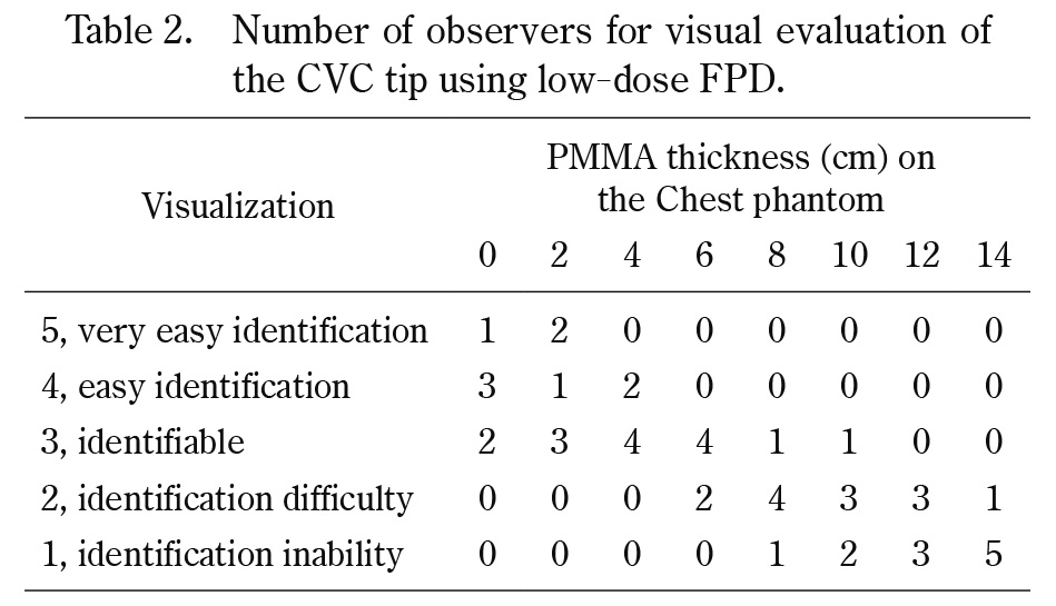
To compare the visual evaluation of the CVC tip, images were obtained for each PMMA phantom thickness in the geometric configuration in Method 1.3. The three types of images were fluoroscopic images, low-dose FPD, and low-dose HF FPD. The images were randomly reordered and transferred to a laptop computer (TOUGHBOOK CF-C2, Panasonic). Five radiologists and an emergency physician examined these images with a DICOM viewer to evaluate the CVC tip visibility. Zooming and grayscale processing were allowed freely during the observation. The visual evaluation was performed using a 5-point Likert scale as follows: 5, very easy identification, all catheters were visualized and the location of the tip was clearly assessed, providing very useful information for CVC insertion; 4, easy identification, catheters were visualized and the location of the tip was assessed, providing sufficient useful information; 3, identifiable, some catheters were difficult to visualize, but the tip could be evaluated; 2, identification difficulty, insufficient information was obtained because some catheters were visualized, but the position of the CVC tip could not be assessed and was indistinct; and 1, identification inability; no information could be obtained because no CVC tip was visualized. All observers were informed of the study objectives and provided their written consent before the study.
1.5 Statistical analyses
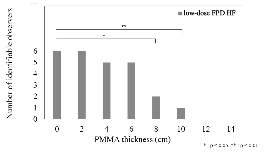
The results of the visual evaluation of the low-dose FPD and low-dose HF FPD were divided into two groups: those in which identification of the CVC tip was possible (score of 3 or higher) and those in which the CVC tip could not be identified (score of 1 or 2). The group with identification of the CVC tip was tested using Dunnett’s test with the PMMA phantom at 0 cm as the reference for each system. Differences were statistically significant at P < 0.05. All statistical processing was performed using the IBM SPSS Statistics version 28 (IBM, Armonk, NY, USA).
Results
2.1 Patient surface dose measurement in chest phantoms
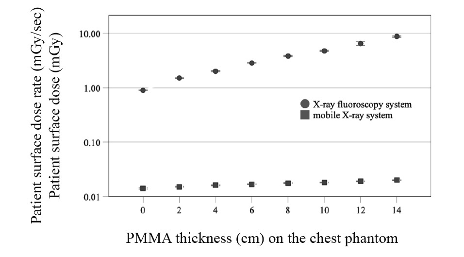
The patient surface dose rates of the X-ray fluoroscopy and mobile X-ray systems are shown in Figure 3. The patient surface dose rate of the X-ray fluoroscopy system exponentially increased with the PMMA phantom thickness. For the mobile X-ray system, a slight increase was observed with increasing PMMA phantom thickness according to the inverse square of the distance by approaching the ion chamber to the focal spot of the X-ray tube. The patient surface dose rate of the X-ray fluoroscopy system with the PMMA phantom at 0 cm was 0.9014 mGy/min, and the patient surface dose of the mobile X-ray system at that time was 0.0142 mGy.
2.2 Evaluation of a CNR of a catheter
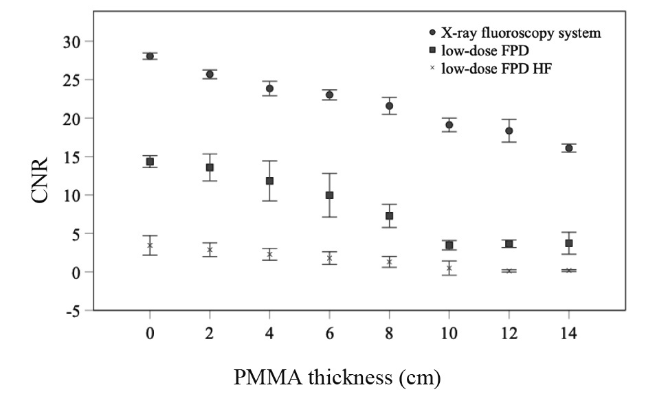
Results of the CNR using the X-ray fluoroscopy system and the FPD and mobile X-ray systems to determine the PMMA phantom thickness are shown in Figure 4. CNRs of the three systems differed. All CNRs were decreased as the PMMA phantom thickness increased. The CNR was better in the X-ray fluoroscopy, low-dose FPD, and low-dose HF FPD, respectively.
2.3 Visual evaluation of the CVC tip image
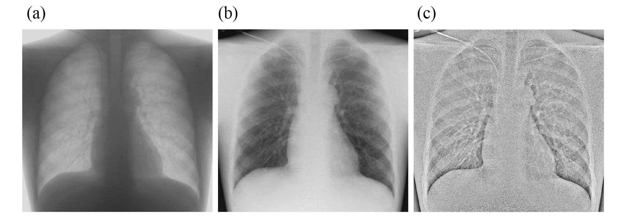
The number of observers for visual evaluation in the three modes is reported in Tables 1, 2, and 3. The number decreased as the PMMA phantom thickness placed on the chest phantom increased. The score allocated by observers for the fluoroscopy system was > 3 for all PMMA phantom thicknesses, which is a clinically usable score. Diagrams of the number of identifiable observers in low-dose and low-dose HF FPD are shown in Figures 5 and 6. There was no significant difference in the number of identifiable observers between low-dose FPD and low-dose HF FPD up to a chest phantom + 6 cm PMMA phantom. Images of the chest phantom + 6 cm PMMA phantom obtained in different modes are shown in Figure 7.
Discussion
In this study, we have proposed and assessed an image-guided CVC insertion technique using the FPD and mobile X-ray system to assess the CVC tip and facilitate speedy image-guided CVC insertion. With this method, it is possible to perform image-guided CVC insertion in a simple manner without the need to move the patient to the fluoroscopy room. In addition, the radiation dose for checking the CVC tip can be significantly reduced.
FPD was clinically introduced in the late 2000s and is frequently used with mobile X-ray systems in hospital wards, emergency rooms, and operating rooms. The mobile X-ray systems are particularly useful for patients who are difficult to move due to severe illness or infection. Currently, radiography in hospital rooms and clinics is permitted within the scope of the medical law. Conversely, the use of an X-ray fluoroscopy system in a hospital room or clinic is not yet approved, and CVC insertion using fluoroscopic-guided is limited to controlled areas. The image-guided CVC insertion technique may also contribute to the immediate treatment of critically ill emergency patients in addition to the CVC insertion technique in the emergency room as described earlier. Catheters that should be speedily inserted in critically ill patients include intra-aortic balloon blockade17) and extracorporeal membrane artificial lungs18). This technique may be effective as both are implanted in the aorta and vena cava around the mediastinum.
To perform an image-guided CVC insertion in actual clinical practice, dose conditions should be set with the lowest possible dose while ensuring image quality that allows for checking of the CVC. In this study, we proposed a new method of CVC insertion under image-guided imaging conditions. To assess the clinical applicability of this method, the minimum doses of the X-ray fluoroscopy system and FPD and mobile X-ray system were compared. In the visual evaluation of a chest phantom, the FPD and mobile X-ray system were used to obtain the image quality to detect the CVC tip when the PMMA phantom placed on the chest phantom was <6 cm. Patient surface doses were significantly higher in all patients undergoing the X-ray fluoroscopy system. For the X-ray fluoroscopy system, the dose also increased with increasing PMMA phantom due to the automatic exposure control. For the FPD and mobile X-ray system, the dose was almost constant due to constant exposure parameters. The minimum dose for the FPD and mobile X-ray system reduced the dose by at least 98% as compared to that of the X-ray fluoroscopy system. On the X-ray fluoroscopy system, the dose is adjusted using an automatic exposure control to ensure a constant image quality. Therefore, this study examined the clinical applicability of FPD and mobile X-ray system at the lowest dose, which resulted in a large difference. The CNR was evaluated for the X-ray fluoroscopy system, low-dose FPD, and low-dose HF FPD. For all systems, the CNR decreased with increasing PMMA phantom. For the X-ray fluoroscopy system, the patient surface dose increased with the PMMA phantom thickness. This may have increased the scattered radiation and decreased CNR. For the low-dose FPD, the CNR decreased from 0 cm to 8 cm PMMA phantom, and then, it was kept at an equilibrium at the lower level until 10 cm. This was considered to be due the dose reaching the FPD being beyond the limit due to the low dose. In the case of low-dose HF FPD, the CNR was low for all PMMA phantom thicknesses; HF emphasizes the catheter contour through high-frequency enhancement, which also emphasizes the noise due to the low dose reaching the FPD, resulting in low CNR. Visual evaluation using the chest phantom was also performed using the X-ray fluoroscopy system (Figure 7a), low-dose FPD (Figure 7b), and low-dose HF FPD (Figure 7c). The score of the fluoroscopy system was maintained above 3 points, which can be assessed for all PMMA thicknesses. No significant difference was observed on the scores between low-dose and low-dose HF FPD. Low-dose HF FPD with low-dose FPD had lower CNR; however, their visual evaluation indicated that they had no significant differences. For visual evaluation, the reader also checked the insertion route when evaluating the CVC tip. This behavior was thought to have influenced the results. When the PMMA phantom placed on the chest phantom was <6 cm, low-dose and low-dose HF FPD were able to evaluate the image of the CVC tip. If the PMMA phantom thickness is converted into the thickness of water based on the density, a 6 cm PMMA phantom corresponds to a thickness of 4.7 cm in the water. The chest phantom is 18.6 cm. Adding the 6-cm PMMA phantom to the chest phantom, the chest thickness is equivalent to 25.7 cm. Since the average Japanese chest thickness is 18.2 cm and the standard deviation is 1.59 cm19), 95% of Japanese are expected to have chest thickness ranging from 15.0 cm to 21.4 cm. Therefore, image-guided CVC insertion using FPD and mobile X-ray system was considered feasible for >95% of Japanese.
Conclusion
In this study, we investigated the clinical applicability of an X-ray-guided CVC insertion method using the FPD and mobile X-ray system. Our results showed that combining the FPD and mobile X-ray systems effectively reduced the radiation dose by at least 98% compared to the method using X-ray fluoroscopy system, while ensuring the CVC visibility. We concluded that this combination of the FPD and mobile X-ray system is particularly effective in emergency room where urgent procedures are required.
Acknowledgments
We would like to express our gratitude to the people in the Department of Radiology, Fukushima Medical University, for their technical support of the experiment. We would also like to thank Dr. Fukuda for his expertise in dosimetry techniques. Finally, we are grateful to the referees for their useful comments.
Conflict of interest disclosure
The authors declare no conflicts of interest associated with this manuscript.
References
- 1. Pires R, Rodrigues N, Machado J, Cruz R. Central venous catheterization:an updated review of historical aspects, indications, techniques, and complications. Transl Surgery, 2:66-70, 2017.
- 2. Dudrick SJ, Wilmore DW, Vars HM, Rhoads JE. Long-term total parenteral nutrition with growth, development, and positive nitrogen balance. Surgery, 64:134-142, 1968.
- 3. Filler RM, Eraklis AJ, Rubin VG, Das GB. Long-term total parenteral nutrition in infants. N Engl J Med, 281:589-594, 1969.
- 4. Padberg FT Jr, Ruggiero J, Blackburn GL, Bistrian BR. Central venous catheterization for parenteral nutrition. Annals Surg, 193:264-270, 1981.
- 5. Fukuda S, Nakajima K, Miyazaki Y, et al. Use of double-lumen peripherally inserted central catheters for safer perioperative management of esophageal cancer patients. J Vasc Access, 16:338-343, 2015.
- 6. Fang S, Yang J, Song L, et al. Comparison of three types of central venous catheters in patients with malignant tumor receiving chemotherapy. Patient Prefer Adherence, 11:1197-1204, 2017.
- 7. Schummer W, Schummer C, Rose N, et al. Mechanical complications and malpositions of central venous cannulations by experienced operators. A prospective study of 1794 catheterizations in critically ill patients. Intensive Care Med, 33:1055-1059, 2007.
- 8. Toshniwal GR, Rath GP, Bithal PK. Flush test—a new technique to assess the malposition of subclavian central venous catheter position in the internal jugular vein. J Neurosurg Anesthesiol, 18:268-269, 2006.
- 9. Kuchle C, Suttmann Y, Wen M. Placement of central venous dialysis catheters without X-ray: safety and feasibility. J Nephrol Ren Dis, 1, 2017.
- 10. Nazarian GK, Bjarnason H, Dietz CA Jr, et al. Changes in tunneled catheter tip position when a patient is upright. J Vasc Interv Radiol, 8:437-441, 1997.
- 11. Robinson JF, Robinson WA, Cohn A, et al. Perforation of the great vessels during central venous line placement. Arch Intern Med, 155:1225-1228, 1995.
- 12. Oropello JM, Leibowitz AB, Manasia A, et al. Dilatorassociated complications of central vein catheter insertion:possible mechanism of injury and suggestion for prevention. J Cardiothorac Vasc Anesth, 10:634-637, 1996.
- 13. Watabe O, Kimura T, Okada K, et al. The safety and reliability of central venous catheterization by means of axillary vein puncture with real-time ultrasound and fluoroscopic guidance. J Jpn Soc Intensive Care Med, 16:163-167, 2009.
- 14. White DR, Booz J, Griffith RV, et al. Report 44 Tissue substitutes in radiation dosimetry and measurement. Journal of the International Commission on Radiation Units and Measurements, 23:14-19, 1989.
- 15. Baba M, Goto M, Hirano M, et al. Investigation of image processing using “catheter/gauze enhancement function” (Japanese). Saitama Housyasen, 62:397-404, 2014.
- 16. Stonelake PA, Bodenham AR. The carina as a radiological landmark for central venous catheter tip position. Br J Anaesth, 96:335-340, 2006.
- 17. Cannon J, Morrison J, Lauer C, et al. Resuscitative endovascular balloon occlusion of the aorta (REBOA) for hemorrhagic shock. Mil Med, 183:55-59, 2018.
- 18. Marasco SF, Lukas G, McDonald M, et al. Review of ECMO (extra corporeal membrane oxygenation) support in critically ill adult patients. Heart Lung Circ, 17:S41-S47, 2008.
- 19. Takeuchi S, Kageyama I, Kato S, et al. Somatometric measurements of university students from 1980 to 1993. Anthropol Sci, 110:185-222, 2002.