Regular Article
Refinement of Retained Austenite in Super-bainitic Steel by a Deep Cryogenic Treatment
2014 Volume 54 Issue 1 Pages 222-226
Details
2014 Volume 54 Issue 1 Pages 222-226
The effect of a deep cryogenic treatment on the microstructure of a super-bainitic steel was investigated. It was shown that quenching the super-bainitc steel in –196°C liquid nitrogen resulted in the transformation of retained austenite to two phases: ~20 nm thick martensite films and some nano carbides with a ~25 nm diameter. Some refinement of the retained austenite occurred, due to formation of fine martensite laths within the retained austenite. The evolution of these new phases resulted in an increase in the average hardness of the super-bainitic steel from 641 to ~670 HV1.
Super-bainitic steel offers a desirable combination of high strength (up to 2.2 GPa), ductility (~30%) and fracture toughness (~45 MPa m0.5).1) The common microstructure of this family of steel consists of ultrafine or nano-size bainitic-ferrite laths and retained austenite (usually more than 20 vol%).2) The retained austenite appears as ultrafine or nano films (<100 nm) between the subunits of bainite and as micron blocks (>1000 nm) between the sheaves of bainite.3) Recent research4) has shown that the retained austenite grains larger than 1 μm are unstable and do not contribute significantly to the ductility of the steel, because they are prone to transform into brittle martensite under the influence of an external stress. Hase et al.5) reported that the blocks of retained austenite could be eliminated and increased ductility obtained by adopting a two-stage bainitic transformation. However, this treatment required a long transformation time (usually >20 hrs),5) even if Co and Al were added to accelerate the bainitic transformation.
Deep cryogenic treatment (DCT) is often used as a heat treatment for hot/cold worked martensitic tool steels and only requires a short processing time (usually <8 hrs).6,7) Increases in the hardness and wear resistance of tool steels, and also improvement in their dimensional stability by the cryogenic treatment have been reported.8) The grain size and volume fraction of retained austenite in a tool steel could be significantly reduced, due to the formation of secondary martensite and some fine carbides.9,10) Conventional bainitic steels have much lower amounts of retained austenite and may not benefit from a cryogenic treatment. In contrast, super-bainitic steels contain large amounts of retained austenite and the current work investigated the potential to refine the retained austenite by deep cryogenic treatment.
The chemical composition of the steel used in this work is given in Table 1. The as-received steel was homogenized at 1200°C for 2 days in a vacuum furnace followed by furnace cooling to ambient temperature. Homogenized specimens were austenitized at 1000°C for 30 min and then isothermally transformed at 200°C for 10 days, 250°C for 4 days and 300°C for 1 day. The prior DCT specimens were obtained by quenching into room temperature water, whereas the post DCT specimens were quenched into liquid nitrogen (–196°C) for 2 hrs and then re-immersed in room temperature water.
| C | Si | Mn | Cr | Mo | Ti | Fe |
|---|---|---|---|---|---|---|
| 0.95 | 0.91 | 1.30 | 2.30 | 0.99 | 0.17 | Bal. |
Optical (Olympus BM51), scanning electron (Sirion 200) and transmission electron (JEM 2010 HT) microscopes were used to examine the microstructures. Optical and SEM specimens were ground and polished using standard techniques and etched in a 4 vol% nital solution. TEM specimens were machined into 3 mm diameter rods, which were sliced into 100 μm discs. Each slice was ground down to 50 μm in thickness using 2000 grit silicon carbide paper, followed by electropolishing at room temperature at 50 V using a twin-jet unit. The electrolyte consisted of 5% perchloric acid, 15% glycerol and 80% methanol.
SEM and TEM micrographs were used to determine the distribution, size and morphology of the retained austenite, bainitic-ferrite and martensite plates. The thickness of lath-shape phases, t, was by determined using the mean linear intercept L = πt/2 method11) in a direction normal to the laths.
A number of 2 mm thick square shape samples (10 mm×10 mm) were ground, polished and slightly etched in 4 vol% nital for the phase characterisation by X-ray diffractomety (Xpert Pro MPD, operating at 40 kV and 45 mA, with Cu Kα radiation). The 2θ scanning angles were from 20° to 100°, with a stepping angle of 0.03342°. Finally, the volume fraction of retained austenite was calculated by measuring the integrated intensities of the (111), (200), (220) and (311) in austenite peaks, and compared with the (110), (002), (112) and (022) bainite peaks,12,13) with a measurement error of about 0.015.
Each hardness value, reported in this work, is the average of at least ten Vickers tests (1 kg).
The microstructures of the prior and post DCT steels are shown in Fig. 1. Typical bainite sheaves (the dark regions) and retained austenite (the white regions) can be seen prior to the DCT (Fig. 1(a)). At a much higher SEM magnification, bainitic-ferrite plates (lower relief) and retained austenite (higher relief) in the shape of micron-size blocks can be seen (Fig. 1(c)). The sheaves of bainite have a common crystallographic orientation and are separated by nano-thick films of retained austenite.3) However, the volume fraction of retained austenite in the post DCT super-bainitic steel is visibly lower (Fig. 1(b)) and significantly refined (Fig. 1(d)).

Optical (top) and SEM (bottom) micrographs of steel samples isothermally transformed to bainite at 300°C for 1 day, (a) and (c) prior DCT, (b) and (d) post DCT.
Bainitic ferrite plates and carbon-enriched untransformed retained austenite were obtained by low temperature bainitic transformation (200–300°C). When they were immediately treated by deep cryogenic treatment (–196°C), carbon-enriched untransformed retained austenite were transformed into fine martensite laths, as shown in Fig. 2. The martensite laths are very fine due to large driving force14) in the process of deep cryogenic treatment. Therefore, the transformation product of the carbon-enriched untransformed retained austenite during deep cryogenic treatment is martensite, rather than bainite (For instance, martensite laths thickness is about 10–20 nm, which is thinner than that of 50–100 nm of bainitic ferrite laths). TEM microscopy revealed that the bainite sheaves consist of nanostructured bainitic-ferrite plates (about 50 nm thick) and very thin retained austenite films as can be seen in the steel to prior DCT when transformed at 200°C for 10 days (Fig. 2(a)).The microstructure of the post DCT steel consists of bainitic-ferrite plates, very thin retained austenite films and newly formed ~20 nm thick martensite laths (Fig. 2(b)). The sub-micron blocks of retained austenite were smaller in the post DCT steel due to the transformation of some of the retained austenite to martensite (Figs. 2(c) and 2(d)).
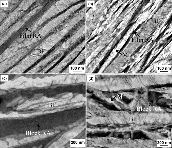
TEM micrographs in the specimens isothermally transformed at 200°C for 10 days, (a) and (c) prior DCT, (b) and (d) post DCT.
The measured thickness of retained austenite shown in Table 2, is consistent with the observed microstructures of the prior and post DCT steels. When the bainitic transformation occurred at 200°C for 10 days, the thickness of the retained austenite films and blocks was 35 and 900 nm in the prior DCT steel, respectively. The post DCT steel had a smaller thickness of retained austenite (10 and 630 nm). Using a higher transformation temperature (i.e. 300°C for 1 day) increased the thickness of the retained austenite (80 and 2970 nm in prior DCT, 35 and 1520 nm in post DCT, respectively). It appears that the refinement of the retained austenite grains was significant in the deep cryogenic treatment.
| Samples | Film RA, nm | Block RA, nm | ||||
|---|---|---|---|---|---|---|
| Temperature, °C | 200 | 250 | 300 | 200 | 250 | 300 |
| Prior DCT | 35±15 | 60±15 | 80±30 | 900±170 | 1180±230 | 2970±530 |
| Post DCT | 15±5 | 20±10 | 35±20 | 630±140 | 810±200 | 1520±420 |
Carbon enrichment defects2) were present in the bainitic-ferrite plates of the prior DCT steel, despite the high Si content of about 0.91 wt%, while very fine and spherical precipitates about 25 nm diameter were observed in the microstructure of the post DCT steel, respectively (Figs. 3(a) and 3(b)). EDS analyses revealed that the precipitates were alloy carbides. Dislocations were generated at the austenite/bainitic ferrite interface,2) while dislocation debris was also evident inside the blocks of retained austenite (Fig. 4).

TEM micrographs in the specimens isothermally transformed at 200°C for 10 days, (a) carbon enrichment defects in bainitic ferrite in prior DCT steel, (b) the carbide formed in post DCT steel and its EDS analysis.

TEM micrograph showing the dislocation debris in the microstructure obtained at 300°C for 1 day, (a) prior DCT and (b) post DCT steels.
The XRD analysis results and measured hardness indicate that the deep cryogenic treatment increased the hardness and decreased the volume fraction of retained austenite (Fig. 5). The post DCT steel had a smaller volume fraction of retained austenite (i.e. 0.21 compared with 0.29 for the same transformation temperature of 200°C) and had a higher hardness (i.e. 670 as to 641 HV1) than the prior DCT steel. For the higher transformation temperature (i.e. 300°C) the hardness was reduced for both treatments (488 and 467 HV1).

The measured retained austenite fraction and hardness.
The calculated transformation temperature and TTT diagram using the MUCG 83.Mod program15) are shown in Fig. 6(a). The calculated TTT diagram confirms that bainite can be obtained from austenite at very low transformation temperatures (200–300°C). As this is an incomplete-reaction phenomenon,16) the carbon content in the carbon-enriched retained austenite (1.56–1.79 wt%) was below the para-equilibrium (Ae3′) phase boundary and the carbon content in the bainitic-ferrite (0.47–0.63 wt%) was less than the predicted T0′ phase boundary (Fig. 6(b)).17) The austenite enriched in carbon can no longer transform to bainite, and the maximum amount of bainite that can be obtained at any temperature was limited and the fraction of retained austenite in the microstructure was more than 20 vol%.
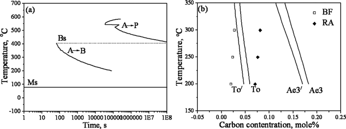
(a) Calculated TTT diagram for the initiation of reaction, (b) carbon concentration in the bainitic ferrite retained austenite of super bainitic steel.
It has been reported that the improvement of hardness for tool steels processed by deep cryogenic treatment can be attributed to the nearly complete transformation of retained austenite to martensite, or the precipitation of carbide particles, or the combination of both these phenomena.18) In the present work, the retained austenite did not completely transformed into martensite and carbides during the deep cryogenic treatment. The martensite start temperature Ms was estimated by the carbon content and composition through the following equation19)
Using the high carbon content in retained austenite (1.56–1.79 wt%) due to enrichment from the low temperature bainitic transformation, the Ms was predicted to decrease from 67°C to –204~–288°C. Therefore, only a small amount of retained austenite is expected to transform into martensite during the DCT process.
The films of retained austenite entrapped between neighbouring sub-units of bainitic ferrite have a higher carbon content than the blocks of reatained austenite located between the sheaves of bainite.20) Both kinds of retained austenite could continue transform into bainite or martensite. Hase et al.5) reported that the blocky austenite was subdivided by newly generated many orientations of bainite in two-stage bainitic transformation. It is reasonable to believe that the martensite has also different orientations in DCT process.
The original nano film and micron/sub-micron block of retained austenite were divided by the newly formed martensite into smaller regions (see Fig. 2), coarse massive retained austenite was fragmented and the microstructure overall was significantly refined. A schematic diagram of microstructure refinement by deep cryogenic treatment is shown in Fig. 7.

Schematic illustration showing the refinement of mixed microstructures. The retained austenite is separated by the newly formed martensite by deep cryogenic treatment.
Previous works had revealed that fine dispersed carbides formed during deep cryogenic treatment could increase up to about 2 vol%.8) In the present work, the formation of carbides was possibly caused by the following reasons. Firstly, the carbide precipitation was caused by martensite and austenite lattice contraction. Because of this shrinkage, carbon atoms were forced to diffuse and form a new carbide nucleus.8) Secondly, a number of carbon enrichment defects were formed in the bainitic ferrite during bainite transformation (see Fig. 3(a)). These carbon enrichment defects were the nuclei of new carbides. In the meantime, some defects were formed during the bainite and martensite transformation, which were greatly enriched in substitutional solutes such as Mn, Mo, Cr, Mo, Ti. They were also the beneficial nucleation sites of carbides.
The effect of cryogenic treatment on toughness of steels has been extensively studied. Some works7,21,22) showed that the small decrease in toughness after cryogenic treatment due to an increase in the amount of martensite. However, Koneshlou et al.6) reported that cryogenic treatment increased the toughness, because the martensite laths are smaller and distributed more uniformly in the microstructure after deep cryogenic treatment. Meanwhile, Hase et al.5) also used two-stage bainitic transformation to refine retained austenite and introduce finer bainite laths in super bainitic steel, which significantly improved the toughness. In the present work, fine martensite laths were produced by deep cryogenic treatment exhibit features similar to those of fine bainite laths produced by two-stage bainitic transformation. The difference is that in the condition of two-stage bainitic transformation, it is the nanoscale bainitic laths that divide retained austenite. The most recent work23) has revealed that multi-step super bainite transformation remarkably improves the toughness owing to the refinement and reduction of blocky MA constituents in medium carbon steels. Therefore, it is expected that the deep cryogenic treatment should increase the toughness, which needs further research.
The refinement of retained austenite grains by deep cryogenic treatment was carried out immediately after a low temperature bainitic transformation. The generation of a multiphase microstructure with a mixture of nanostructured bainitic-ferrite, martensite, retained austenite and carbides was observed after deep cryogenic treatment. In this the newly formed martensite separated the retained austenite into smaller regions. It appears that deep cryogenic treatment is an effective way to refine the amount of retained austenite in super bainitic steels and further increased the hardness and stability of the microstructure.
Authors express their thanks to the financial support from the International Science and Technology Cooperation Program of China under grant No. S2012ZR0211 and from Hubei Provincial Department of Science and Technology under Grant No. 2012BAA14005.