Regular Article
Effect of the Quality of Furan Moulding Sand on the Skin Layer of Ductile Iron Castings
2014 Volume 54 Issue 6 Pages 1288-1293
Details
2014 Volume 54 Issue 6 Pages 1288-1293
The paper presents the results of investigations of the influence of the quality of moulding sand with furfuryl resin hardened by paratoluenosulphonic acid, on the formation of microstructure and surface quality of ductile iron castings. Within the studies different moulding sands were used: moulding sand prepared with fresh sand and moulding sands prepared with reclaimed sands of a different purification degree, determined by the ignition loss value. Various concentrations of sulphur and nitrogen in the sand moulds as a function of the ignition loss were shown in the paper as well as the gas emission and gas evaporation rate from the moulding sands. A series of experimental melts of ductile iron in moulds made of moulding sand characterized by different levels of surface-active elements (e.g. sulphur) and different gas evolution rates were performed. It was shown that there exist a significant effect of the quality of the sand on the formation of the graphite degeneration layer.
Production of castings (especially thin-walled) of ductile iron, in loose self-hardening moulding sands with furfuryl resin hardened by paratoluenosulphonic acid, brings a danger of forming defected casting microstructure, which the most often occurs in its surface layer.1,2,3,4,5,6,7,8,9,10) This unfavourable effect is caused by sulphur contained in a hardener of resin binders, which enters the surface layer causing degradation of a nodular graphite into flake graphite. In such case the degenerated surface layer can cause stress raising in the casting, similar to a notch, so all useful properties are reduced, especially the fatigue limit and impact resistance. The graphite degradation in the surface layer is the most critical for thin wall castings, where it could become more than 10% of the total section. It affects also castings of thicker walls, due to the long solidification time providing an extended metal/mould interaction time.
The authors of the hereby paper undertook the effort of making test castings of ductile iron in moulds made of a fresh moulding sand and of a moulding sand with a reclaim of various purification degrees. Then the castings were subjected to investigations leading to determination the microstructure of their skin layer directly adhering to the mould. Simultaneously, the gas evolution and sulphur and nitrogen contents were determined for moulding sands, of which moulds were made.
Experimental castings applied in investigations were test bars, according to the ASTM A 536-84 standard, of a wall thickness in the working part: 13 mm. Four casting moulds were made of moulding sands marked with symbols: MT1-1 through MT1-4. All tested moulding sands were prepared with furan-urea Kaltharz U404 resin and 100T3 hardener. The following moulding sand composition was applied:
– Matrix (high-silica sand or reclaim) 98.5 wt.%,
– Resin: Kaltharz U404 1.0 wt.%,
– Hardener 100T3 0.5 wt.%.
Moulding sands matrices were as follows:
– High-silica sand – moulding sand MT1-1,
– Reclaim 1 (after one cycle of a reclamation treatment) – moulding sand MT1-2,
– Reclaim 2 (after two cycles of a reclamation treatment) – moulding sand MT1-3,
– Reclaim 3 (after three cycles of a reclamation treatment) – moulding sand MT1-4.
Ignition loss of moulding sands prepared with the fresh sand and reclaims are presented in Table 1. Reclaims were obtained in the experimental mechanical, rotor reclaimer.11)
| Moulding sand notation | Characteristic of moulding sands | |
|---|---|---|
| Kind of matrix | Ignition loss of moulding sand | |
| % | ||
| Moulding sand MT1-1 | High-silica sand | 1.47 |
| Moulding sand MT1-2 | Reclaim 1 | 2.89 |
| Moulding sand MT1-3 | Reclaim 2 | 3.86 |
| Moulding sand MT1-4 | Reclaim 3 | 4.26 |
It can be noticed that the ignition loss of moulding sand after three cycles of a reclamation treatment is 2.9 times larger than of moulding sand prepared on the fresh high-silica sand.
The experimental melt was performed in an induction furnace. The furnace charge consisted of the following materials: Sorelmetal, silicon of technical purity, Fe–Mn and steel scrap. After metal heating to a temperature of 1490°C the bath was hold for 2 minutes and then spheroidising and innoculation by the bell method was carried out. For the spheroidisation treatment the foundry alloy Fe–Si–Mg (6 wt.% Mg) was used, while for the modification the Foundrysil modifier was used in amount of 0.5 wt.%. The pouring temperature was app. 1400°C. Four Y block ingots were prepared from self-hardening moulding sands (MT1-1 through MT1-4) of a characteristic given in Table 1. Diversification of ignition losses of moulding sands was a result of different number of cycles, in which participated the given moulding sand matrix.
The thermal load of a moulding sand during test castings, expressed by a ratio of casting mass to moulding sand mass was: mcast : msand = 1:1.6 (at the casting mass equal 1.7 kg). The average apparent density of the compacted moulding sand was app. 1600 kg/m3. After the mould pouring with ductile iron the temperature was measured in the mould during casting cooling. Ductile iron of the following chemical composition was obtained: C – 3.56%; Si – 2.99%; Mn – 0.29%; P – 0.046%; S – 0.011%; Cr – 0.03%; Mg – 0.046%; Cu – 0.02%. The performed strength investigations allowed to determine the grade of the melted ductile iron as ASTM A536 80-55-06.
The view of the four Y ignots test castings are presented in Fig. 1.
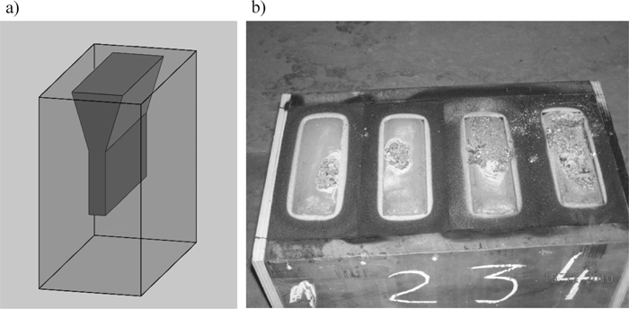
Outline of the position of Y block test cast in the test mould (a), four Y ignots casted in moulds prepared with sand MT1-1 through MT1-4 of different matrix quality (b).
Samples cut out from lower parts of test bars were subjected to metallographic and strength investigations. Metallographic investigations were carried out by means of the optical microscope Leica MEF-4M. The microstructure was assessed at magnifications 25 and 100×. The cast steel classification, on the basis of the static tensile test was performed by means of the Zwick/Roell Z050 device equipped with the extensometer Macro. The testing rate was 0.008 s–1.
The literature data4,8,9) emphasize a disadvantageous influence of too high sulphur and nitrogen content in moulding sands on the microstructure of the obtained castings surfaces.
Within quality investigations of the reclaimed matrix the sulphur and nitrogen content in 4 moulding sands (listed in Table 1) were performed.
The obtained results presented graphically in Fig. 2 confirm the accumulation effect of sulphur and nitrogen in moulding sands after several reclamation treatments. The increase of sulphur and nitrogen content in moulding sands as a function of ignition losses exhibits nearly linear character. Thus, it seems possible to determine indirectly these elements content in moulding sands on the basis of knowledge of ignition losses and its characteristic similar to the one presented in Fig. 2.

Sulphur (S) and nitrogen (N) content in moulding sands with Kaltharz U404 resin (1 wt.%) and 100T3 hardener (0.5 wt.%). Ignition losses as in Table 1.
During a casting production process an intensive thermal destruction of organic components of moulding sands occurs, causing a large emission of gases. These gases constitute a threat for the casting quality, since they can migrate into a casting and worsen its surface.
Own investigations of gases emission were carried out according to the original method developed in the Faculty of Foundry Engineering AGH.12) Investigations of the gases emission were performed according to the original method developed in the Faculty of Foundry Engineering, AGH UST. The schematic presentation of the experimental stand is given in Fig. 3. A sample of the investigated moulding sand of a roll shape of dimensions φ 50 × 50 mm, compacted by a moulder’s rammer stroke, is poured with liquid cast iron of a temperature of 1400°C. Gases emitting from the sample - after pouring it with liquid metal - are led by means of a steel pipe via the drying system and the capsule with active carbon into a tightly sealed container with liquid, from which they push out the liquid. The weight of displaced liquid was measured as a function of time.
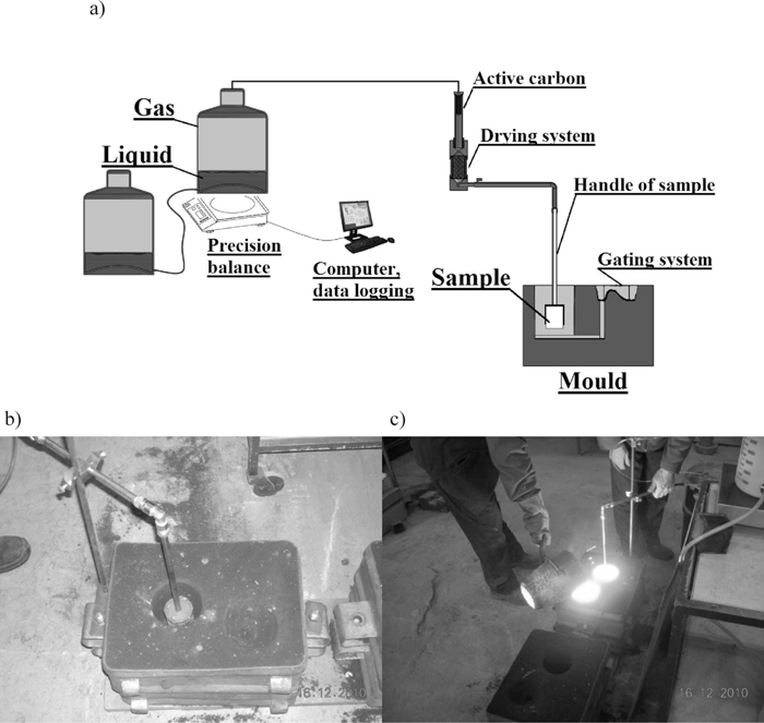
Scheme of stand of measurement of gas volume (a), mould with the sample before casing (b), mould with the sample after casting (c).
Investigations of the amounts and kinetics of gases generated in the process of pouring test bars were performed for the given above variants of moulding sands (MT1-1 through MT1-3), which characteristic is presented in Table 1. The obtained gases emissivity pathways are presented in Fig. 4 as a time function. It can be noticed, that the amount of gases generated from moulding sand with furfuryl resin depends on the ignition loss of this sand. With an increase of ignition losses an amount of gases generated in the mould pouring process also increases. The highest intensity of gases emission takes place directly after the mould pouring with liquid metal. The analysis of pathways indicates that both the volume and kinetics of emitted gases depends essentially on the ignition losses of moulding sands.
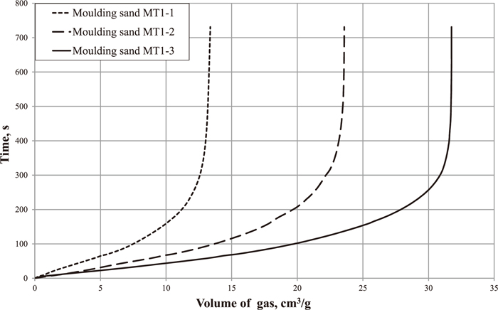
Volume of gases emitted by the investigated moulding sands in the process of their pouring with liquid metal. Pouring temperature: 1400°C.
On the basis of macroscopic photographs (Fig. 5) of casting surfaces differences in their qualities in dependence on the material from which the mould was made, can be seen. The pictures represents the surface of 6 cm × 3.4 cm cuted from the center of the bottom part of each Y block. It should be emphasised that all castings were performed under the same conditions, it means that from one melt 4 castings were made. The casting made in the mould from the moulding sand MT1-1 has the best, visually assessed, surface quality. Certain small defects are seen on the casting made in the mould of moulding sand MT1-2 and these defects become more visible on the castings made in the mould of moulding sand MT1-3 and MT1-4. Investigations of gas evolution rate of moulding sands MT1-1 through MT1-3 confirmed that the amount of gases, which source is the foundry mould material is, in practice, linearly dependent on ignition losses of moulding sands. The obtained castings confirm this fact, since casting defects formed in them are defects being the result of a high evolution rate of gases.
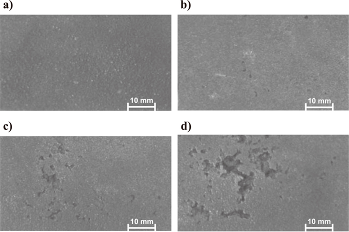
Experimental castings: a) Casting made in the mould of moulding sand MT1-1, b) Casting made in the mould of moulding sand MT1-2, c) Casting made in the mould of moulding sand MT1-3, d) Casting made in the mould of moulding sand MT1-4.
Microstructures of ductile iron obtained for the investigated moulding sands is presented in Figs. 6, 7, 8, 9 in such a way that the dark zone on the bottom means the metal and moulding sand contact.
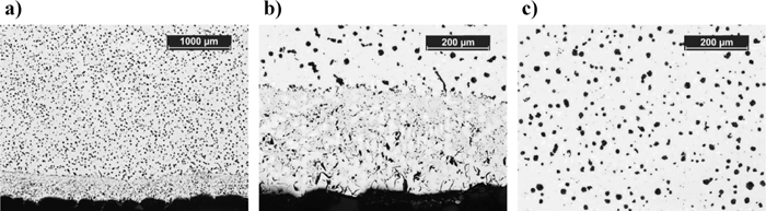
Photographs of the microstructure of the casting made in the mould of moulding sand MT1-1: a) Magnification 25× – view from the moulding sand side, b) Magnification 100× – view from the moulding sand side, c) Magnification 100×, middle of the casting.
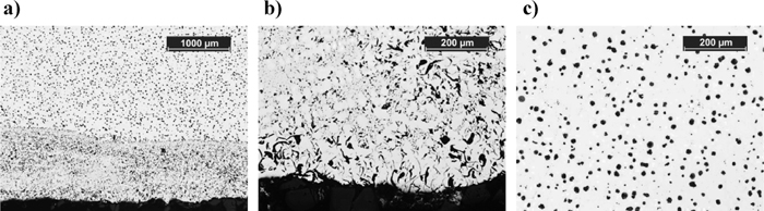
Photographs of the microstructure of the casting made in the mould of moulding sand MT1-2: a) Magnification 25× – view from the moulding sand side, b) Magnification 100× – view from the moulding sand side, c) Magnification 100×, middle of the casting.
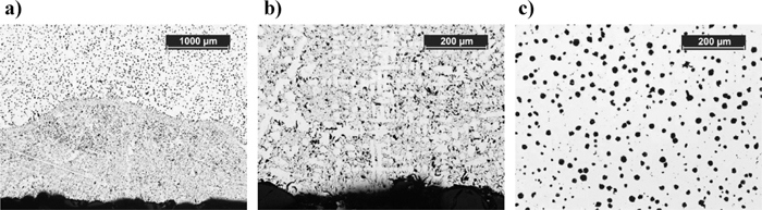
Photographs of the microstructure of the casting made in the mould of moulding sand MT1-3: a) Magnification 25× – view from the moulding sand side, b) Magnification 100× – view from the moulding sand sidec) Magnification 100×, middle of the casting.

Photographs of the microstructure of the casting made in the mould of moulding sand MT1-4: a) Magnification 25× – view from the moulding sand side, b) Magnification 100× – view from the moulding sand side, c) Magnification 100×, middle of the casting.
The presented above results of investigations of microstructures of castings indicate that with the increase of ignition losses of moulding sands, of which the mould was made, (moulding sand MT1-1 through moulding sand MT1-4) the thickness of the flake graphite layer – located at the metal-mould contact – increases. The mould production with using reclaimed materials of higher ignition losses (it means of larger amounts of spent binder left on matrix grains) causes that the thickness of flake graphite layer increases. On the basis of casting microstructures investigations the average thickness of degenerated nodular graphite and pealite layers – which are forming from the moulding sand side - were estimated. The results are presented in Fig. 10. It can be noticed, that the thickness of these layers is increasing when the ignition loss of moulding sand out of which the mould was produced is increasing. In case of the casting produced of fresh moulding sands (for which sulphur and nitrogen content was determined as being 0.09 wt.% and 0.07 wt.%, respectively, and ignition loss = 1.47 wt.%) the thickness of these layers is the smallest. However, also in this case there is a zone in which the nodular graphite, much-desired from the casting point of view, was degenerated. In case of the casting 4 microstructure (Fig. 5), for which the mould was produced of the moulding sand containing 0.28 wt.% of sulphur and 0.18 wt.% of nitrogen (ignition loss = 4.26 wt.%) the maximum thickness of the degenerated graphite layer was nearly 1.5 mm.

Influence of the moulding sand kind of which the mould was produced on the maximum thickness of the degenerated nodular graphite and pearlite layers.
(1) The ignition loss of the moulding sand after three cycles of the reclamation treatment is nearly three times larger than that of the moulding sand prepared on the fresh high-silica sand. Also matrix indicates significant increases of ignition losses when the number of cycles increases, which indicates the accumulation of a spent binder - on matrix grains - not removed during the reclamation treatment preceding the moulding sand preparation.
(2) Multiple reclamation treatment causes accumulating of sulphur and nitrogen content in moulding sands. Sulphur and nitrogen content in moulding sands increase analysed as a function of their ignition losses indicates nearly linear character.
(3) The most intensive gas evolution occurs directly after the mould pouring with liquid metal. Under the investigated conditions, the highest emission of gases occurs in the first 90 seconds after pouring with metal. An application of a moulding sand of higher ignition losses causes increasing of gas emissions.
(4) Castings performed in the mould of the fresh moulding sand indicate the best surface quality. When the number of the reclamation cycles was increased the worsening of casting surfaces occurred.
(5) Along with an increase of ignition losses of moulding sands, of which the mould was produced, the thickness of the flake graphite layer increases. Producing mould with using reclaims of higher ignition losses (it means of larger amounts of left over spent binders on matrix grains) causes that the thickness of the flake graphite layer increases.
This work was supported by Polish NCN project UMO-2011/03/B/ST8/05869.