Regular Article
Mathematical Model for Decarburization Process in RH Refining Process
2014 Volume 54 Issue 7 Pages 1560-1569
Details
2014 Volume 54 Issue 7 Pages 1560-1569
A three-dimensional mathematical model for natural decarburization process of ultra-low carbon Al killed steel during RH refining has been established. The decarburization behavior in RH degasser was discussed on the basis of a comparison between simulation data and the actual plant trials ones. The effects of the different initial carbon content, initial oxygen content, the lift gas rate and inside diameter on decarburization were investigated. The results showed that when the dissolved oxygen concentration was 0.08% in the molten steel, the flow rate of gas injected through the up-leg was 120 Nm3/h, the inside diameter of up and down-leg was 650 mm, under these conditions, the initial carbon content was 0.03%, 0.023% and 0.015%, respectively, after about 25 minute, the average carbon content in molten steel was 0.011%, 0.01% and 0.0008%. The final dissolved carbon content is related to the initial dissolved oxygen content in molten steel. The average carbon concentration and the decarburization rate of the molten steel will decrease with the increasing of the initial dissolved oxygen content. The effects of different inside diameter of up and down-leg were also compared, it shows that the increasing of the diameter of up/down-leg will promote decarburization effectively, which can increase the circulation flow rate and promote the reaction rate.
In order to improve the mechanical properties of the cold rolled steel sheets and to deal with the change from the batch-type to the continuous annealing, the production of ultra-low carbon (ULC) steel has been increasing.1,2,3) With the growing demand of ultra-low carbon steel, it became essential to establish and validate mathematical model of refining process for ultra-low carbon steel. In recent years, the RH (Ruhrstahl–Heraeus) degassing process has been widely used in the secondary refining of steel. Decarburization, removal of nitrogen, hydrogen, inclusions, and alloy additions, etc. can be conducted at various efficiency levels depending on the specifications of the final product. It is well known that during RH treatment, the molten steel circulates between the vacuum vessel and the ladle through the snorkels, and the degree of vacuum, the circulation rate as well as stirring have an important effect on the rate of degassing. The influence factors depend on the gas injection rate through nozzles, depth of injection, inside diameter of the snorkels, shape of the snorkels, length and numbers of snorkels, quantity of hot metal in the ladle and the temperature of the hot metal. Now there are two kinds of decarburization model which forced on decarburization and natural decarburization. The purity of molten steel will be affected when the oxygen is injected into the liquid steel through the top feeding port while the chamber is in vacuum. It is more popular with natural decarburization. It is very important to know the decarburization behavior and conditions in the present RH-degasser in order to obtain an effective decarburization and to develop a new process in natural decarburization. Due to the invisibility of RH, it is difficult to observe and measure carbon content directly in typical positions of the equipments with high temperature and reaction. T. Kuwabara et al.4) proposed a reaction zone model and evaluated first the decarburization in the bulk of molten steel by experiment-taking sample in the up-leg and the down-leg in vacuum, and the circulation flow rate. M. Susa and K. Nagata5) analyzed the transfer reaction of the carbon and the oxygen from the surface to the molten steel, coupling of the chemical reaction, the carbon and the oxygen diffusion were taken into account within the diffusion layer in the molten steel in order to explain the change of the concentrations in molten steel. And some other mathematical models simulating the decarburization reaction in the RH-degasser have been developed. Many of them are usual differential models6,7,8) which a volumetric coefficient can be used in the papers. In the previous studies, mathematical calculations of the reaction between carbon and oxygen were only taken into two-dimensional model, without considering the influence of three-dimensional flow on reaction.
Since carrying out meaningful experiments to define these conditions is very difficult, using computational/mathematical models is becoming more necessary. There had been a lot of predecessor studies on decarburization,9,10) but the verifications of their models were based on the comparison with the predecessor study before theirs. In present work, a CFD-based mathematical model is established for circulation decarburization in RH degasser, considering the equilibrium of elements according to 210 t RH for ultra-low carbon steel. Compared with the forced decarburization, since the cycle decarburization can reduce the free oxygen content of the liquid steel at the decarburization endpoint, it can reduce the amount of added aluminum which is used as a deoxidizing metal, at the same time it can also reduce the content of nonmetallic inclusions in the product. This article focuses on the mathematical model of cycle decarburization. It is based on taking full account of the balance between carbon and oxygen, the effect of reaction between the carbon and oxygen on the reaction rate and using the turbulence model to establish a more precise three-dimensional dynamic model aiming to simulate the decarburization process. In order to verify the reliability of the mathematical model, the simulation results were compared with the results of site sampling. Moreover, the effects of different initial carbon content and inside diameter of vacuum snorkels on decarburization were investigated. The main objective of the investigation was to assess the influence of the above parameters on decarburization in the ladle and to supply the further advices to the industries.
The decarburization process is very complex during the RH refining processes, the following assumptions were made:
(1) The molten steel is considered as steady and incompressible Newton flow;
(2) The bubbles is spheres and uniform in size, not considering their coalescence and breakup;
(3) No considering the fluctuation of molten steel in vacuum chamber;
(4) The driving force is caused by density difference between liquid and gas phase. The force between liquid and gas phase is drag force.
Two-phase flow model is used to calculate fluid flow.
Governing equations as following:
Continuity equation
| (1) |
Momentum equation
Phase liquid:
| (2) |
Phase gas:
| (3) |
Where γα, γβ shows respectively volume fraction of phase α, β, ρα, ρβ shows density of phase α, β (kg/m3), Uα, Uβ shows vector of velocity of phase α, β (m/s), Uαi, Uαj, Uβi, Uβj shows vector of velocity Ux,y,z of phaseα, β (m/s), p shows pressure for all phase (Pa), μαeff, μβeff shows effective viscosity of phase α, β (kg/ms). Mα, Mβ is described as the interfacial forces acting on phase α, β due to the presence of phase β, α. The define of effective viscosity μαeff and Momentum source Mα, Mβ can be found in predecessor study.11,12)
2.2. Decarburization Model Considering Chemical Reaction and Fluid FlowIn constructing a decarburization model which considers the mass transfer of carbon and oxygen in the RH, the following assumptions were made.
(1) Only C and O are reacted within the system;
(2) The C, O dissolves in the molten steel in the form of dilute solution, and C, O element uniformly distributes at initial moment;
(3) The reaction between slag and molten steel is ignored.
For the decarburization reaction, the multi-component model is established in the present paper.
| (4) |
Where ΓCIeff is effective diffusion coefficient of carbon element, kg·m–1·s–1, SC is source term of mass fraction of carbon element, kg·m–3·s–1, [%C] shows respectively the mass concentration of carbon in molten steel in vacuum vessel.
Where ΓCIeff can be solved by the equation as following:13,14)
| (5) |
Where ΓC is diffusion coefficient of carbon element, kg·m–1·s–1, μt is eddy viscosity, kg·m–1·s–1, Sct is turbulence Sc number.
Reaction between C and O in vacuum vessel molten steel will be poignant because of lower CO partial pressure. By using theory of gas pump, liquid steel will be lifted to up-leg, vacuum until down-leg and circulation flow of liquid steel has been formed. Equation of decarburization and the reaction Gibbs free energy as following:15)
| (6) |
| (7) |
| (8) |
Where T is the temperature (K), K is the equilibrium constant, PCO is the CO partial pressure (pa), [%C], [%O] is the respectively mass concentration of carbon and oxygen, fC, fO are C, O respectively activity coefficients of carbon and oxygen.
The formula of decarburization velocity can be written as following:
| (9) |
Where, v is the chemical reaction velocity, (kgm–3s–1), Cv, Cθ are the respectively carbon instantaneous volumetric concentration and equilibrium volumetric concentration (kgm–3), αk is the decarburization mass coefficient (s–1), t is the reaction time (s).
The carbon and oxygen transfer from the molten steel to the reaction interface and chemical reaction occurs in the interface and CO bubbles can be created and escaped from the interface which consists of vacuum vessel and free surface of the liquid steel. In this paper, after carbon and oxygen element come to the interface, the mass concentration of carbon and oxygen tending to balance volumetric concentration can be assumed. Mass source terms of carbon and oxygen can be written as:16)
| (10) |
| (11) |
Where Kc and Ko are apparent rate constant of carbon and oxygen (s–1) respectively, [%C]e, [%O]e are mass equilibrium concentration of carbon and oxygen, according to carbon and oxygen mol mass ratio can be written as:
| (12) |
The concentration of carbon and oxygen in reaction interface can be written as following:
| (13) |
Where K is the equilibrium constant of carbon and oxygen reaction at 1873 K, and can be deduced by Eq. (14).
| (14) |
Mass source term of carbon in reaction of carbon and oxygen can be deduced from Eqs. (10), (11), (12), (13) as following formula:
| (15) |
C, O element interaction coefficients are as follows:16)
C, O element activity coefficients can be calculated from following formulas:
| (16) |
| (17) |
The decarburization reaction in RH process mainly takes place at the free surface of the molten steel in RH vacuum vessel. The decarburization rate of molten steel in vacuum vessel depends on mass transfer coefficient of carbon or oxygen, Yamaguchi et al.3) proposed critical ratio of carbon and oxygen element, while the ratio of carbon and oxygen is larger than the critical value, the restrictive step will be diffusion of oxygen, otherwise, diffusion of carbon can be restrictive step. The critical value is about 0.52 in lab experiment by Suzuki et al.17) The formulas can be deduced as:
| (18) |
| (19) |
| (20) |
| (21) |
| (22) |
Where m is the weight of molten steel in the ladle (kg), Q is the circulation flow rate of molten steel (kg·s–1), akc, ako are the mass transfer coefficient of carbon and oxygen in molten steel (m3·s–1).
Circulation flow rate can be written as:4)
| (23) |
Where G is the argon flow rate (Nm3·s–1), D is the snorkel diameter (m), P1, P0 are the respectively surroundings pressure and vacuum vessel pressure (Pa).
The mass transfer coefficient of carbon can be written as:3)
| (24) |
| (25) |
The partial pressure of CO in vacuum vessel can be deduced as,18)
| (26) |
Where Sv is the surface area of vacuum vessel molten steel (m2), h is the distance from reaction location to free surface (m), P0 is the pressure in vacuum vessel (pa), β is the pressure conversion coefficient, P is the saturation pressure of CO bubble (pa).
Because the liquid pole and drop swarms will be created with argon escaping from molten steel, the decarburization will be increased, the decarburization of these areas belong to free surface decarburization and rate constant of decarburization is ten times in vacuum vessel.
2.3. Boundary ConditionsThe boundary conditions of the simulation about the flow within the RH relates to the inlet, the upper surface of the vacuum chamber, the upper surface of the ladle, the ladle wall and the vacuum chamber wall, which was defined as follows: (1) The inlet is argon (the lift gas) inlet, whose flow rate equals to the actual flow ones; (2) The boundary condition near the free surface of the vacuum chamber is degassing boundary condition, and the degassing boundary behaves as an outlet boundary to the gas, but as a wall to the molten steel; (3) Ignoring the level fluctuation, the velocity gradient of liquid steel and the argon near the ladle top surface are set to zero; (4) At the other wall, for the turbulent flow, as the fluctuations of momentum weakens rapidly near the wall, it is necessary to take account of the effect of turbulence weakened and the relative enhancement of the layer flow, the wall functions controls flow behavior, the velocity gradient of liquid steel and argon is zero; (5) The gradient vector is zero at the symmetry plane.
The mass concentration gradient of carbon and oxygen are set zero at any boundary.
| (27) |
In the present paper, computational fluid dynamics model CFX 11.0 was applied to solve flow field of the molten steel, the carbon concentration and the oxygen concentration of the molten steel and the decarburization reaction in RH vacuum vessel and the ladle. Half of the geometry model was established considering symmetry of the RH firstly, the geometric model and meshing grids are shown in Fig. 1.
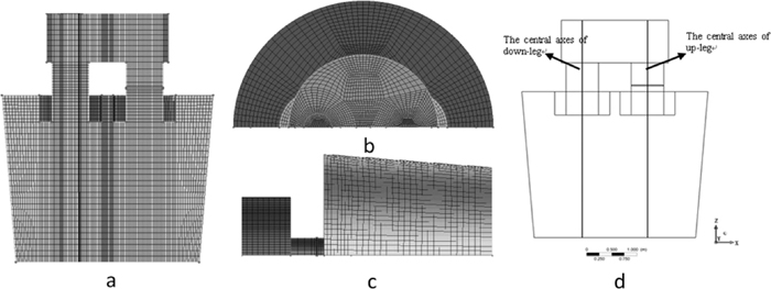
Geometric model and mesh configuration of RH: (a) front (b) top (c) right (d) sampling position.
The calculated flow pattern of the molten steel in the ladle and the vacuum vessel is shown in Fig. 2. After the lift gas is injected into the molten steel, the argon gas floats at once and drives the molten steel moving up and the molten steel enters the up-leg and the vacuum vessel. The Circulation has been formed. The flow pattern of the molten steel shows two recirculation flow zones. The largest one is in the left of molten steel downstream from the down-leg, and the relatively small recirculation is at the bottom which is the right area of the ladle. Meanwhile, the molten steel circulation is formed from ladle to the vacuum vessel. The molten steel directly scours the bottom from down-leg. The life of the ladle bottom will be decreased. Maybe the dead zone will appear at the two recirculation region and affect the distribution of the carbon, for the uneven distribution of the carbon concentration in the ladle.

Calculated flow pattern of steel melt in ladle and vacuum vessel.
Knowledge of the trend of carbon content at various points in the ladle during decarburization treatment in RH is essential for process improvement and development. The distribution of carbon content at centerline of up-leg and down-leg at 1200 s is shown in Fig. 3. The carbon content of the up-leg is first rising and then going down smoothly. Consequently, the first rising stage occurs in the vacuum chamber, decarburization occurs at the free surface in the vacuum chamber leads to this phenomenon, the liquid steel with high carbon content reaches the vacuum chamber through the up-leg, then the decarburization occurs at the free surface and the carbon content of the liquid steel which is below the free surface rises. Subsequent decreasing area appears at the bottom of the ladle, which is due to the liquid steel dropping down to ladle through the down-leg after the decarburization. The low carbon content liquid steel fills in the area below up-leg under the effect of circulation, thereby the lower carbon content liquid steel gather at the bottom of the ladle below up-leg which forms a turning point of the mass fraction of carbon element. From the figure, it can be seen that the average carbon content is about 0.0023%, 0.0014% at up-leg and down-leg side, respectively. The average carbon content at down-leg side is lower than the up-leg side.

Distribution of carbon concentration in snorkel of RH at 1200 s.
We can find that the simulation result meets the practical data by comparing the numerical simulation with the practical ones which operational conditions are similar to the simulation ones in Fig. 4. The result of the stimulation meets the results of site sampling not very well at the early stage of the decarburization. For the following reasons: 1) the sampling location is a point while stimulation results is average; 2) the actual measurement must have some errors; 3) there is a few error between the assumption of stable pressure and the actual situation, and the following study of these issues is needed.

Comparison of numerical simulation with the actual ones.
The gas flow rate is 120 Nm3/h in the operation, processing time is 1500 s, the inside diameters of up-leg and down-leg all are 650 mm, initial oxygen content was 0.08%, the initial carbon contents were 0.015%, 0.023% and 0.03%. In order to discuss the influence of the different initial carbon content on decarburization process, the cloud distributions of different initial carbon content at 1500 s are shown in Fig. 5. The chart shows that when the initial carbon content is 0.015%, the final carbon content is 0.00109%–0.00122%, when the initial carbon content is 0.023%, the final carbon content is 0.0007%–0.00161% and when the initial carbon content is 0.03%, the final carbon content is 0.0007%–0.002%.

The effect of different initial carbon content on carbon distribution at 1500 s, the initial carbon content: a) 0.015%, b) 0.023%, c) 0.03%.
The influence of different initial carbon content on final carbon content is shown in Fig. 6. The chart shows that when the initial dissolved oxygen content is 0.08%, the carbon content is 0.015%, 0.023% and 0.03%, the final carbon content will be 0.0008%, 0.01% and 0.011% after 1500 s refining.

The effects of different initial carbon content on average carbon content at various time.
The decarburization rate is affected evidently by the oxygen content of the molten steel. The lift gas flow rate is 120 Nm3/h in the operation, processing time is 1500 s, the inside diameters of up-leg and down-leg are all 650 mm, initial carbon content is 0.03%, the initial oxygen contents are 0.08%, 0.07%, 0.06 and 0.05%. The relationships between the carbon content, the oxygen content and the time at each case of the different initial oxygen content are showed in Figs. 7 and 8.

C concentration changes with the different initial [O] concentration.

O concentration changes with the different initial [O] concentration.
When the initial oxygen content is 0.08%, the rich dissolved oxygen could transfer to the interface, and the decarburization reaction occurred deeply which is showed in Figs. 7, 8. After 1500 s, the oxygen of molten steel is about 0.05%, the final carbon content is about 0.001%. With the decreasing of the initial oxygen content, the dissolved oxygen of molten steel will decrease after decarburization when the initial oxygen content is 0.05% and the final oxygen content of the molten steel is 0.01–0.02%. The restrictive step of the decarburization is the dissolved oxygen diffusion instead of the carbon diffusion, and the rate of decarburization will decrease rapidly. The carbon concentration will be enhanced in 1500 s. When the initial dissolved oxygen content is 0.08%, the average carbon concentration of the molten steel is 0.0011% at 1500 s. If the initial dissolved oxygen is 0.05%, the average carbon concentration of the molten steel is 0.0024% at 1500 s. The average carbon concentration and the decarburization rate of the molten steel will drop with the increasing of the initial dissolved oxygen content.
The critical ratio of dissolved C and O is about 0.5217) by experiment, when the ratio of the dissolved carbon concentration and the dissolved oxygen concentration is less than it, the sufficient dissolved oxygen can transfer to the reaction interface, and the restrictive step is the diffusion of the dissolved carbon. If the ratio of the dissolved carbon and the dissolved oxygen is larger than it, the dissolved oxygen concentration of the molten steel will be low relatively. Poor dissolved oxygen can transfer to the reaction interface; the restrictive step is the diffusion of the dissolved oxygen. The initial dissolved carbon concentration of molten steel is 0.03%, the initial dissolved oxygen concentration is 0.05%, the ratio of [C] and [O] is larger than the critical ratio of [C] and [O], and the restrictive step of the decarburization reaction is the diffusion of the dissolved oxygen to the reaction interface. If the initial dissolved oxygen is 0.05%, the average dissolved carbon concentration is 0.0024% at 1500 s, with low decarburization rate and the high final dissolved carbon content. It is impossible that carbon content will be rapidly decreased to the target value. If the initial dissolved carbon is 0.03%, the initial dissolved oxygen content is much higher than 0.06%.
The cloud distribution of the carbon content at the different initial oxygen content at 1500 s shows in Fig. 9. The cloud distributions of the carbon content were roughly the same at 1500 s. The carbon content will decrease with the increasing of the molten steel initial oxygen. When the initial oxygen of the molten steel is 0.05%, the maximum carbon content is 0.002% and the minimum carbon content is 0.00148% at 1500 s. When the initial oxygen content is 0.08%, the maximum carbon content is 0.002% and the minimum carbon content is 0.0007% at 1500 s. It is beneficial to obtain lower carbon content of the molten steel for increasing the initial oxygen content of the molten steel.

The effect of different initial oxygen content on carbon distribution at 1500 s, the initial oxygen content: a) 0.05%, b) 0.06%, c) 0.07%, d) 0.08%.
The inside diameters of up-leg and down-leg have significant influence on the circulation of molten steel in RH degasser. The effects of inside diameter on decarburization were discussed in this section and the results can be used to put forward suggestions on how to optimize the design of RH and to supply further advices to the industries. The carbon element is set for 0.03% in the operation, initial oxygen elements for quality score is 0.08%, the lift gas flow is 120 Nm3/h, processing time is 1500 s, inside diameters of up-leg and down-leg will be changed, its working conditions are: (1): the inside diameters of up-leg and down-leg are 650 mm, (2) the inside diameters of up-leg and down-leg are 500 mm (3) the inside diameters of up-leg and down-leg are 350 mm. (4): the inside diameters of up-leg and down-leg are 650 mm and 350 mm, respectively.
The influence of inside diameter on decarburization is shown in Fig. 10. The distribution curves are almost similar shown in Fig. 10, but the maximum carbon content increases with the decreasing of inside diameter. When the inside diameters of up-leg and down-leg are all 650 mm, the final carbon content reached maximum 0.00176% and minimum 0.0007%. When the inside diameters of up-leg and down-leg are all 350 mm, the final carbon content reached maximum 0.006% and minimum 0.00229%. When the inside diameter of up-leg is 650 mm, 350 mm for the down-leg, the final carbon content reached maximum 0.006% and minimum 0.00282%. Thus it can be seen that the inside diameter has great influence on decarburization, the decarburization rate decreases with the decreasing of the inside diameter, which can be explained that when the injection gas keeps steady, the circulation of molten steel flow decreases and the rate of molten steel increases with the inside diameter, so it indicates that the molten steel doesn’t react completely and then drops into the down-leg, the decarburization of molten steel is not strong. The inside diameter is the limiting of the decarburization process, so we should increase the inside diameter of up-leg and down-leg as far as possible.

The distribution of C concentration in different snorkel diameter conditions, the snorkel diameter of up-leg and down-leg: a) 650 mm; b) 500 mm; c) 350 mm d) 350 mm, 650 mm.
The carbon element varies with the time under different inside diameters conditions is shown in Fig. 11, it can be seen that the decarburization rate decreases and the final carbon element raises with the decreasing of the inside diameter. Due to the decreasing of the inside diameters, the circulation flow slows down in RH, the mass transfer rate of carbon and oxygen elements to the reaction interface slow down, the decarburization reaction rate decreases. At the same time, the injection gas flow keeps steady, when the inside diameters reduced, the molten steel circulation rate increased, the carbon oxygen elements at reaction interface are not completely reacted and then taken away, which is the restrictive factor of reaction. The decarburization rates can be improved by an increasing in diameter of the up-leg and down-leg snorkel. Hence, it is essential to optimize this parameter to achieve maximum refining efficiency with minimum refining time, thus improve the productivity of the secondary refining process.

The carbon element changes with time under different inside diameters conditions, the snorkel diameter of up-leg and down-leg: a) 650 mm; b) 500 mm; c) 350 mm d) 350 mm, 650 mm.
The effects of different inside diameters on decarburization at 1500 s were shown in Fig. 12. It can be seen that when the inside diameters of up-leg and down-leg are 650 mm, the average carbon content is 0.0011% at 1500 s, when the inside diameters of up-leg and down-leg are 500 mm, the average carbon content is 0.0022% at 1500 s, when the inside diameters of up-leg and down-leg are 350 mm, the average carbon content is 0.0049% at 1500 s, when the inside diameters of up-leg and down-leg are 350 mm and 650 mm, respectively, the average carbon content is 0.0044% at 1500 s. It shows that increasing the snorkel diameter is effective to promote decarburization, which can increase the circulation flow rate and promote the reaction rate.

The effects of different inside diameters on decarburization at 1500 s.
The injected lift gas in up-leg makes the molten steel circulate from the vacuum vessel to the ladle. The circulation rate of the molten steel would be increased with the increasing of the lift gas rate. And the effect of refining would be improved. The initial carbon content is 0.03% in the operation, initial oxygen content is 0.08%, processing time of is 1500 s, inside diameter of up-leg and down-leg are all 650 mm, the lift gas flow rate will be changed, the working conditions are: (1) 72 Nm3/h (2) 96 Nm3/h (3) 120 Nm3/h.
The relation between the average carbon concentration and the time at the different lift gas flow rate is showed in Fig. 13. The average dissolved carbon concentration at 1500 s with various lift gas flow rate is showed in Fig. 14. The decarburization rate will be increased with increasing of the lift gas flow rate, and the average carbon concentration of the molten steel will be low at 1500 s from Figs. 13 and 14. If the lift gas flow rate is 72 Nm3/h, the average carbon concentration is about 0.0016% at 1500 s, if the lift gas flow rate is 120 Nm3/h, the average carbon concentration is about 0.0011% at 1500 s. The reason is that the circulation flow rate will be increased with the increasing of the lift gas flow rate, the transfer coefficient of [C] and [O] to reaction interface will be increased too. The reaction between [C] and [O] will take place easily at the interface.

[C] concentration changes with the different lift gas flow rates.

[C] concentration with the different lift gas flow rate at 1500 s.
In the present investigation, a decarburization model was established to study the influence of different initial carbon contents and inside diameters on decarburization in RH degasser, Specific findings include:
(1) The decarburization process can be forecasted preferably through the decarburization mathematical model.
(2) The factors order of the influence of the process parameters on the final carbon content of the molten steel from strong to weak is approximately as follows: inside diameter of the snorkel, initial oxygen content, lift gas rate, and initial carbon content.
(3) The carbon concentration in the vacuum down-leg free surface decreases to the equilibrium concentration rapidly, the decarburization rate in the vacuum free surface is faster than that in the other location, and the restrictive step will not react between carbon and oxygen under that situation.
(4) The carbon concentration distribution is uneven, the carbon concentration in the vacuum vessel is lower than that in the ladle, and the carbon concentration in the up-leg is higher than that in the down-leg. The lowest carbon concentration appears in the down-leg free surface, the highest carbon concentration appears in the ladle right wall free surface in the longitudinal section.
(5) The effect of the initial dissolved oxygen on the decarburization rate is remarkable. When the content of dissolved oxygen is much higher, the restrictive step of the decarburization reaction will be the dissolved carbon diffusion. Contrariwise, the restrictive step will change into the dissolved oxygen diffusion.
(6) The inside diameter of the snorkel has great influence on decarburization. The decarburization rates can be improved by increasing the diameter of the up-leg and down-leg, in order to increase the circulation rate of the molten steel in the ladle.
The authors gratefully express their appreciation to National Natural Science Fund of China (51174024) and the National High Technology Research and Development Program of China (863 Program) (2012AA03A505) for sponsoring this work.