Regular Article
Inclusion Evolution during Modification of Alumina Inclusions by Calcium in Liquid Steel and Deformation during Hot Rolling Process
2015 Volume 55 Issue 10 Pages 2115-2124
Details
2015 Volume 55 Issue 10 Pages 2115-2124
The formation mechanism of Al2O3–CaS based inclusions in Al-killed steel was studied by industrial trials and thermodynamic calculations of various calcium aluminates and the precipitated CaS. The chemical activities of CaO and Al2O3 of various calcium aluminates were expressed as a function of CaO and Al2O3 content of CaO–Al2O3 inclusions respectively by the third liner fitting equation obtained from different researchers. Massive Al2O3–CaS based inclusions were generated with a decrease of temperature of molten steel and subsequent solute segregation during casting. Based on the shapes of CaS layer, there are two formulations to consider: 1) the crescent-shaped CaS layer surrounded calcium aluminates was generated by reaction between dissolved Al, S and modified calcium aluminates or diffusion of S dissolved in inclusions; 2) the oval shape layer associated with calcium aluminates was generated by collision or adsorption of calcium aluminates and the precipitated CaS. In addition, the deformation mechanism of inclusions with different modification extents and sizes during hot rolling was proposed.
The production of clean steel involves the controlling, elimination, or modification of nonmetallic inclusions. In Al-killed steels, alumina is the main type of inclusion. Calcium treatment, by wire feeding, is commonly used to modify solid alumina inclusions to calcium aluminates, which exists in a fully or partially liquid phase. Liquid inclusions can improve steel castability, but make inclusions size larger during hot rolling process if these inclusions have not been completely removed before casting, which can significantly affect the mechanical properties of final products.1) Previous researchers had extensively studied on CaO–Al2O3, MgO–CaO–Al2O3 or MgO–CaO–Al2O3–CaS inclusions, such as their characteristics and formation mechanism. Ye et al.2) found alumina inclusions were changed by calcium treatment with the path of Al2O3→CA6→CA2→CA→CAX(liquid) until the Al2O3 activity became so low that precipitation of CaS was occurred. Guo et al.3) proposed there were two manners for Al2O3 inclusion modification during LF refining process: the first manner was Al2O3→low modified calcium aluminates→liquid calcium aluminates, and the second was Al2O3→MgO·Al2O3 spinel→CaO–MgO–Al2O3 multi-component inclusion. Jiang et al.4) proposed that steel/slag reaction time had great effect on inclusion types, compositions and shapes. With the increase of reaction time, solid MgO–Al2O3 and MgO-based inclusions were finally changed into CaO–MgO–Al2O3 system inclusions with lower melting temperature, while shapes of inclusions varied in the route of blocky/angular →near spherical →spherical. Wang et al.5) studied the effect of CaS formation on the evolution of Al2O3–CaO inclusions in low-carbon Al-killed steel and found that the formation of dense CaS shells around the inclusions was mainly due to the reaction between the Al2O3–CaO inclusions with the dissolved S and Al in melt. Yang et al.6) showed that calcium treatment could generate many large inclusions and the modification effect would be dramatically decreased by the formation of large amount of CaS inclusions. Verma et al.7) reported that immediately after calcium treatment CaS formed adhering to alumina or spinel, and longer after calcium treatment the CaS disappeared and spinels were fully or partially modified.
Although so many works have been done in the past, previous researchers mainly focused on the transformation of inclusions with high CaO content and low CaS content. Few studies have been published on formation mechanism of Al2O3–CaS based inclusions in slab, some of which contained less CaO or MgO. In addition, the deformation mechanism during hot rolling process was rarely reported. Although Guo et al.3) reported non-metallic inclusions deformation for Al-killed steel during compact strips production, it was mainly restricted to small size inclusions (<20 μm in plates). In this work, inclusions characteristics and variation in molten steel, slab and hot rolled plates were investigated based on the comprehensive sampling of steel making and hot rolling process by SEM-EDS (Scanning Electron Microscopy-Energy Dispersive Spectroscopy) and ASPEX®. Besides, thermodynamic calculations of various calcium aluminates and the precipitated CaS were performed to explain the formation mechanism for better controlling. Furthermore, the deformation mechanism with various modification extents and sizes in hot rolled plates was proposed in order to understand inclusions deformation mechanism and thus reduce the occurrence of large size inclusions.
Two heats industrial trials were carried out in Qian’an Steel Corporation to study the formation, deformation mechanism and inclusions characteristics.
During the experiment, the process to produce pipeline steel was as follow, hot metal pretreatment→ basic oxygen furnace (BOF)→ ladle furnace (LF)→ RH →continuous casting (CC)→ hot rolling. The steel making process was carried out in a 210 t basic oxygen furnace. After tapping into a ladle, the steel was deslagged, and then a new synthetic slag was added, as well as deoxidizer and the remaining alloys. When the molten steel had the right temperature and chemical composition, the ladle was transferred to the ladle furnace station. The highly basic and strong reducing refining slag was generated to make S content less than 0.0080% and alloy was added to deoxidize and meet the composition requirement during LF refining. After LF refining, the ladle was transferred to RH for degassing and removing non-metallic inclusions. After 30 mins RH treatment, 400 meters Ca wire was fed into liquid steel with a speed of 300 m/min and then soft bottom blowing by argon gas was carried out with the flow rate of 10 Nl/min for 10 mins. Finally, the slabs with thickness of 230 mm were produced by continuous casting and hot rolled into plate with thickness of 20 mm.
Pail samples and slag samples were collected from ladles just at the end of LF refining (LF End), at the end of RH refining (RH End), after soft bottom blowing 10 mins (SB 10 mins) and in the tundish after molten steel level was stable. Rectangular pieces (25 mm×25 mm×20 mm thickness) and cylindrical samples (φ5×40 mm), 20 mm from the bottom of the pail samples, were machined. Slab samples (25 mm×25 mm×20 mm thickness), 50 mm from the intrados of slab and plate samples (20 mm×20 mm×20 mm thickness) were also cut from slabs and plates respectively. These metallographic samples were polished by SiC paper and diamond suspensions to characterize the inclusions. The chemical compositions of the steel samples and slag samples were analyzed with chemical methods. Inclusions were observed by scanning electron microscopy (SEM) and ASPEX®, whose compositions were evaluated by energy dispersive spectrometry (EDS).
The compositions of refining slag at LF End are listed in Table 1. By adding synthetic slag and aluminum to the slag, the content of FeO+MnO in slag was decreased to <1.2% and slag basicity was increased to >5.0 at LF End, which was benefit for deep desulfurization of the molten steel and ensured the stable subsequent calcium treatment. The compositions of the molten steel heat 1 and heat 2 at different step are listed in Table 2. A small amount of calcium concentration at LF End was detected, which may be from the residual calcium of alloy and the reaction between Al alloy and CaO in the refining slag. Besides, total oxygen concentration was obviously decreased during RH treatment, possibly resulting from the floatation of inclusions. After the feeding of Ca wire, calcium concentration was significantly increased and then was slightly decreased owing to reaction with alumina inclusions in molten steel. Finally, total calcium concentration of 20 ppm and 17 ppm in slab were detected in heat 1 and heat 2 respectively.
| CaO | SiO2 | Al2O3 | FeO+MnO | Basicity |
|---|---|---|---|---|
| 40–42 | 7–8 | 30–34 | <1.2 | 5–6 |
| Heat 1 | Heat 2 | |||||||
|---|---|---|---|---|---|---|---|---|
| Al | S | T.Ca | T.O | Al | S | T.Ca | T.O | |
| LF End | 0.0523 | 0.0021 | 0.0009 | 0.0026 | 0.0521 | 0.0014 | 0.0007 | 0.0020 |
| RH End | 0.0421 | 0.0023 | 0.0006 | 0.0021 | 0.0409 | 0.0016 | 0.0005 | 0.0015 |
| SB 10 min | 0.0412 | 0.0019 | 0.0028 | 0.0024 | 0.0397 | 0.0014 | 0.0022 | 0.0016 |
| Tundish | 0.0413 | 0.0018 | 0.0022 | 0.0018 | 0.0385 | 0.0015 | 0.0019 | 0.0013 |
| Slab | 0.0410 | 0.0016 | 0.0020 | 0.0019 | 0.0382 | 0.0012 | 0.0017 | 0.0010 |
Total oxygen was analyzed by the inert gas fusion impulse infrared absorption spectroscopy method. Other chemical compositions were obtained by ICP-AES.
In this work, at least 300 inclusions with the size of >1 μm were detected by ASPEX for each of the samples. Because of similar inclusions characteristics for heat 1 and heat 2, the variation of inclusions compositions of heat 1 at different step is shown in Fig. 1, where the value of X-axis represents for the location of sampling, and the value of Y-axis for the average value of inclusions compositions in molten steel and slab. One thing to note is that all inclusions compositions are normalized to unity and other components excluding MgO, Al2O3, CaO and CaS are ignored, which is not of any interest to study alumina inclusions modification. It can be seen from Fig. 1, before calcium treatment, components of inclusions at LF End and RH End were mainly Al2O3, CaO and MgO, while they became Al2O3, CaO and CaS after calcium treatment. In addition, inclusions compositions was significantly changed after calcium treatment, one of the most obviously changes was that the content of CaS in inclusions was apparently increased and the content of Al2O3 was decreased while the content of CaO was firstly increased then decreased from RH End to tundish owing to the feeding of Ca wire into molten steel after RH refining.
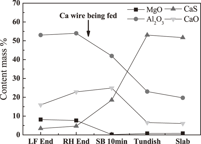
The variation of inclusions compositions at different step.
To better understand the transformation process of inclusions before and after calcium treatment, inclusions with all sizes at LF End and RH End were projected in Al2O3–MgO–CaO ternary phase diagram and others at soft blowing 10 mins, tundish and slab were projected Al2O3–CaS–CaO according to the variation of inclusions compositions in Fig. 1. Because the modification of alumina during LF refining had been fully studied by previous researchers,4,6,9,10) present work mainly focuses on the transformation of inclusions after LF refining and distribution of inclusions at different step is shown in Fig. 2, where the low melting region surrounded by solid line in the ternary phase diagram was obtained by FactSage 6.2 at 1873 K. At LF End, inclusions were mainly calcium aluminates and calcium magnesium aluminates, of which a small amount had located into the low melting point area as shown in Fig. 2(a). At RH End (before calcium treatment), the observed inclusions were mainly calcium aluminates with low melting point or close to low melting point and the number of inclusions were significantly decreased especially for the size of 1–5 μm as shown in Fig. 2(b), which indicates the modification of alumina is possible due to the strong steel/slag reaction with well dynamic condition during RH treatment. After the Ca wire was fed into molten steel and after soft blowing for 10 mins, lots of calcium aluminates were shifted away from low melting point and modified to Al2O3–CaS–CaO (less) complex inclusions and the number density of inclusions were rapidly increased from 6.25/mm2 to 10.49/mm2 shown in Fig. 2(c). As the standing time further was increased, inclusions were continuously modified to Al2O3–CaS based inclusions containing less CaO content and the number density of inclusions were slightly decreased to 7.48/mm2 shown in Fig. 2(d). During casting process, inclusions were still Al2O3–CaS based inclusions and the number density of inclusions slightly were increased to 10.22/mm2.
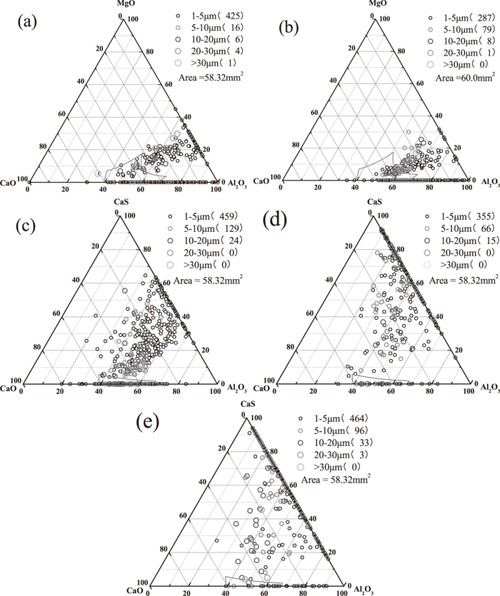
Distribution of inclusions at different step in the MgO–CaO–Al2O3 or CaO–CaS–Al2O3 phase diagram (a) LF End; (b) RH End; (c) Soft Blowing 10 mins; (d) Tundish; (d) Slab.
The element mapping of typical oxide inclusions at different step for heat 1 is shown in Fig. 3, where inclusions (a), (b) and inclusion (c) are from LF End and RH End respectively, and inclusions (d), (e) , and (f) are from soft blowing 10 mins, tundish and slab respectively. It’s important to note that inclusions shown in Fig. 3 only represent for a typical type during corresponding step, not for all inclusions. At LF End, two typical spinels with an outer calcium aluminates layer were formed shown in Figs. 3(a) and 3(b), where Al distributed almost over the whole inclusion; Ca distributed in the outer surface while Mg concentrated zone seemed to be incompatible and complementary with Ca enriched layer. Besides, O concentrated zone seemed to be same with Mg concentrated zone. At RH End, calcium aluminates with elements uniformly distributed similar to Fig. 3(c) were mainly detected which shows Al2O3 based inclusions had been fully modified into calcium aluminates with liquid. Compared with inclusions of Figs. 3(a) and 3(b), Ca concentrated zone became larger almost over the whole inclusion while Mg concentrated zone became less as well as Al concentrated zone was almost constant, which indicates Mg element of spinel was gradually replaced by dissolved Ca in molten steel from the outer of inclusions to the inner. After calcium treatment and soft blowing for 10 mins, calcium aluminates with a small amount of sulfur distributed at outside were generated shown in Fig. 3(d), and Ca distributed almost over the whole inclusion while S concentrated zone was less in the outer surface and seemed to be incompatible and complementary with Al enriched zone. As the standing time was further increased and molten steel temperature decreased, in tundish, Ca still distributed almost over the whole inclusion while S concentrated zone was increased and Al concentrated zone was decreased shown in Fig. 3(e). During casting process with lower molten steel temperature, Al concentrated zone became less and S concentrated zone was continuously increased while Ca concentrated zone still distributed almost over the whole inclusion so that it looked a CaS based inclusion with a small amount of calcium aluminate distributed at outside. If you observes these CaS layers of Figs. 3(d)–3(f) carefully, there is a subtle difference for the shape of CaS layers between Figs. 3(d) and 3(e)–3(f): the shape of CaS layer of Fig. 3(d) is in the shape of a crescent while that of Figs. 3(e)–3(f) is convex and presents near oval. As a whole in Fig. 3, before calcium treatment, Mg concentrated zone seemed to be gradually reduced until no Mg concentrated zone was detected and Ca concentrated zone seemed to be gradually increased to cover the whole inclusion while Al concentrated zone always distributed the whole inclusion. After calcium treatment, Al concentrated zone was gradually decreased and S concentrated zone began to precipitate while Ca concentrated zone did not change and always distributed the whole inclusion. The corresponding transformation mechanism will be explained below.
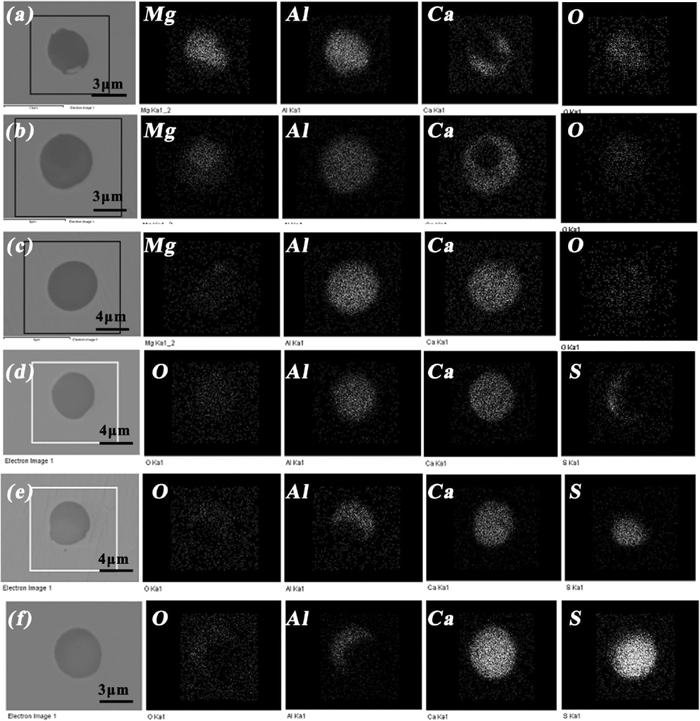
Element mappings of typical oxide inclusions (a) spinel type with a small amount of calcium distributed at outside; (b) spinel type with more amount of calcium distributed at outside; (c) calcium aluminate with elements uniformly distributed; (d) calcium aluminate with a small amount of sulfur distributed at outside; (e) calcium aluminate with more amount of sulfur distributed at outside; (f) CaS inclusion with a small amount of aluminum distributed at outside.
To understand the effect of inclusions compositions on size in slab, the variation of inclusions compositions with different sizes is shown in Fig. 4(a), where the value of X-Axis represents for the range of inclusions size, while the value of Y-Axis for the average content of inclusions component in different inclusions size range. Besides, it is divided into five parts including A+CA6, CA6+CA2, CA2+CA, CA+C12A7, C12A7+C3A respectively, where C and A mean CaO and Al2O3 respectively, by dot line according to CaO and Al2O3 content of inclusions. It is noticed that it only expresses a trend of larger size inclusions closer to low melting point. It can be seen from Fig. 4(a) that inclusions size tended to become larger with the increase of CaO content and the decrease of CaS content in slab, possibly because inclusions with larger CaO/Al2O3 ratio had lower melting point according CaO–Al2O3 binary phase diagram which made inclusions easier to aggregation and growth. Figures 4(b)–4(e) shows these typical inclusions morphology and component of corresponding different inclusions size range of Fig. 4(a).
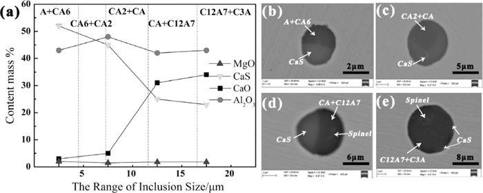
The variation of inclusions compositions with different sizes in slab (a) and corresponding typical inclusion morphology (b) inclusion with size of 4 μm composed of a mixture of A+CA6 and CaS; (c) inclusion with size of 7 μm composed of a mixture of CA2+CA and CaS; (d) inclusion with size of 11 μm composed of a mixture of CA+C12A7, CaS and spinel. (e) inclusion with size of 16 μm composed of a mixture of C3A+C12A7, CaS and spinel.
To better understand inclusions evolution during modification of different oxide inclusions by calcium, formation thermodynamics of oxide inclusions and calcium sulfide are performed.
For Al-killed steel, the dissolved oxygen activity before calcium treatment is determined by the following equation:
| (1) |
| (2) 11) |
and the equilibrium between calcium and dissolved oxygen in steel can be described as the following equation:
| (3) |
| (4) 11) |
The activity coefficient of each element in molten steel is calculated by Eq. (5) where
| (5) |
The equilibrium relationship between Al and Ca can be obtained by combining Eqs. (1) and (3). Because the Al2O3 inclusions are obviously modified into calcium aluminates after calcium treatment, the activities of Al2O3 and CaO are very important to calculate the stability phase diagram of various calcium aluminates. However, the published activity data of two oxides in the CaO–Al2O3 system from literatures2,3,14,15,16) are quite different because of the using of different methods. To obtain relatively better data, the results from different researchers are ploted in Fig. 5, where solid line denotes third liner fitting relationship and thus the activities of Al2O3 and CaO can be expressed by the following equations:
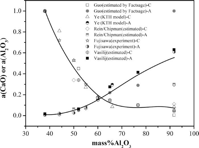
Equilibrium between Als and S with different CaO in CaO–Al2O3 system inclusion at 1873 K.
When [mass%Al2O3]inclusion range is from 36 to 91, the activities of Al2O3 and CaO for various typed calcium aluminates can be expressed as the following Eqs. (6) and (7):
| (6) |
| (7) |
It can be seen from the above Eq. (7) can better calculate the activity of CaO because of the R2 value close to 1, while the R2 value of Eq. (6) is less than that of Eq. (7), mainly owing to the huge difference of Al2O3 activity for CA6 from different researchers.2,3,12,13,14,15,16,17) According to the above third liner fitting relationship, the activities of Al2O3 and CaO of various typed calcium aluminates are listed in Table 3.
| CaO–Al2O3 type | C3A | C12A7 | CA | CA2 | CA6 |
|---|---|---|---|---|---|
| Mass%Al2O3 | 38 | 52 | 65 | 78 | 92 |
| a(Al2O3) | 0.0046 | 0.0536 | 0.2467 | 0.2827 | 0.5102 |
| a(CaO) | 1.0000 | 0.3860 | 0.1036 | 0.0884 | 0.0460 |
In the calculation, the composition of the molten steel is taken from the average of compositions of heat 1 and heat 2 at RH End. To analyze the formation and evolution of calcium aluminates, the stability phase diagram of various calcium aluminates is calculated as shown in Fig. 6. As shown, with Ca concentration in molten steel increasing, Al2O3 inclusions are modified to calcium aluminates with higher CaO content. In the case of dissolved Al is 0.04%, C3A begins to be formed when Ca is more than 0.0065 mass%, C12A7 begins to be formed when Ca is more than 0.0010 mass%, CA begins to be formed when Ca is more than 0.0002 mass%, which indicates Al2O3 modification by calcium is very easy in molten steel at 1873 K. The symbols shown in the figure denotes the present results. At RH End without calcium treatment, Al2O3 inclusions were modified into C12A7, which is in good agreement with Fig. 2(b). At soft blowing 10 mins after calcium treatment, calcium aluminates were continuously modified toward C3A, which is not in agreement with Fig. 2(c). The main difference is that most of calcium aluminates in Fig. 2(c) contains CaS. To clarify the formation mechanism of CaS, the equilibrium relationship between Ca and S in different melting temperatures is described as
| (8) |
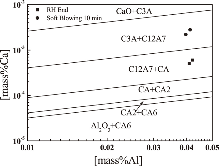
The stability phase diagram of various calcium aluminates.
CaS inclusions may be generated directly by the reaction between sulfur and calcium, shown as Eq. (8). Stability diagram of CaS at different temperature is obtained shown in Fig. 7 where the activity of CaS is considered as unity in this calculation and 1873 K, 1814 K, and 1791 K represents for the temperature of molten steel, casting and liquid phase line respectively. These symbols denote the industrial trial results and locate under the curves of 1873 K, which means single CaS inclusions is difficult to form in melt. For example, when Ca and S concentration is 0.0022% and 0.0018% respectively in tundish, the temperature of the precipitated CaS is 1802 K, which is below the temperature of casting(1814 K). So the precipitated CaS mainly occurs in the casting process.
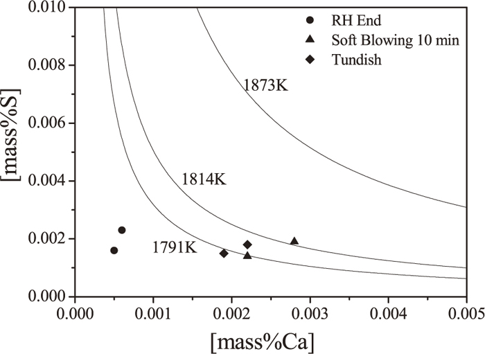
The equilibrium relationship between Ca and S for CaS precipitation.
In addition, sulfide capacity of inclusions plays a very important role for the precipitation of CaS. To analysis the mechanism of CaS precipitation on the surface of inclusions, sulfide capacity of various calcium aluminates was discussed according to KTH model17) shown in Fig. 8. As shown, sulfide capacity of inclusions was increased by sequence of CA6→CA2→CA→C12A7→C3A and decreased with the decrease of temperature, which means the dissolved sulfur of well modified calcium aluminates is easier to precipitate during casting. Thus, it is a possible reason forming a crescent-shaped CaS layer surrounding calcium aluminates shown in Fig. 4(e).
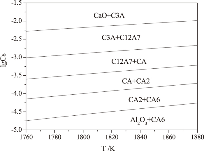
Sulfide capacity of various calcium aluminates at different temperatures.
Considering the effect of dissolve oxygen on the precipitated CaS due to the existed competition between S and O for Ca in the molten steel, the precipitated CaS at the surface of calcium aluminates can be expressed as Eq. (10) by coupling Eqs. (1), (2) and (8). Figure 9 shows the equilibrium relationship between [mass%Al]2/3[mass%S] and the molten steel temperature for the precipitated CaS by combining with various calcium aluminates, where the activity of CaS is considered unity. As shown, CaS is relatively easier to precipitate with the decrease of the molten steel temperature during casting process. These symbols denote the industrial trial results and locate between the curves of C12A7+CaS and C3A+CaS, which means the precipitated CaS is mainly on the surface of C3A. However, some low modified calcium aluminates surrounding a CaS layer were also detected. The possible reason is that low temperature and higher S concentration resulting from segregation at the end of solidification make Eq. (10) continuously proceed in the direction of forming CaS.
| (10) |

The equilibrium relationship between [mass%Al]2/3[mass%S] and the molten steel temperature for CaS precipitation by combining with various calcium aluminates.
All kinds of oxide inclusions with different deformation extent in hot rolled plates were investigated and the elemental mapping of some typical oxide inclusions is shown in Fig. 10, of which Fig. 10(a) shows some low modified inclusions surrounded by a CaS layer with a shape of crescent were not deformed, and the EDS for inner core suggests it was a mixture of CA6 and CA2. Some inclusions with slight deformation along the rolling direction were observed shown in Fig. 10(c), and the EDS for inner core shows it was a mixture of CA2 and CA. The corresponding elemental mapping results show that CaS layer with a shape of oval associating with oxides were likely to separate from the oxide core along the rolling direction and this phenomenon became more obvious for the one of Fig. 10(d) whose inner core was a mixture of CA2 and CA containing less spinel. By comparison, there was a CaS based tail behind the inclusion which was nearly taken off from the matrix inclusion shown in Fig. 10(d). From the above, two points seems to be induced: 1) these low modified calcium aluminates seemed to be difficult to be deformed; 2) the CaS layer with a shape of oval associating with low modified calcium aluminates was easier to be deformed and even separate from the oxide core along the rolling direction.
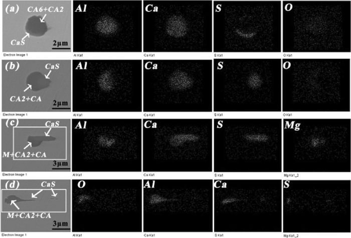
Elemental mapping of typical small size oxide inclusions in hot rolled plates with various deformation extents.
In addition, three typical larger size string oxide inclusions are also observed shown in Fig. 11. The first type (Fig. 11(a)) seemed to deform continuously along with steel matrix, and the EDS showed this inclusion was a favorable modified calcium aluminates with a mixture of C3A+C12A7 and less spinel. The components were almost uniform over the whole inclusion excluding a less spinel concentrated region, and morphology of inclusion looked smooth and continuous. Figure 11(b) shows the second type which looked like a string, and the EDS shows it was a mixture of C3A+C12A7, CaS and spinel. The elemental mapping shows that a favorable modified calcium aluminates seemed to be divided into several parts by CaS and spinel particle and each part of calcium aluminates looked smooth. Figure 11(c) shows the third type was still a string but more irregular than the above two, and the EDS shows it was a mixture of C12A7+CA, CaS and spinel. The elemental mapping shows that the insufficiently modified calcium aluminates also could be divided into several irregular parts by CaS particle and spinel. This inclusion composition was similar to that of the inclusion in Fig. 4(d), so it was supposed to originate from that type one in Fig. 4(d).

Element mappings of typical larger size string oxide inclusions in hot rolled plates.
According to the above analysis, mechanisms of inclusions transformation and formation are proposed. At the end of LF refining, a small amount of Mg and Ca was generated in molten steel due to the feeding of Al alloy and reactions (12) and (13) taken place, thus they reacted with existed Al2O3 based inclusions to form MgO–Al2O3 spinel and low modified calcium aluminates respectively expressed by reactions (14) and (15), which has been reported by different researchers.3,4,5,6)
| (12) |
| (13) |
| (14) |
| (15) |
During RH refining, reactions (16) or (17) were taken place to generate better modified calcium aluminates based on the following two reasons: (1) CaO content of inclusions was increased and MgO content was decreased shown in Fig. 1, which indicates MgO in inclusions could be reduced by dissolved Ca to form CaO; (2) Ca concentrated zone distributing at outside was gradually increased and Mg zone inner was decreased while Al concentrated zone was almost unchanged shown in Figs. 3(a)–3(c), which shows that Mg rather than Al was reduced by Ca.
| (16) |
| (17) |
| (18) |
After calcium treatment, Ca concentration in molten steel obviously was increased from 6 ppm to 28 ppm, reactions (16) and (17) speeded up, which made MgO content of inclusions continuously decrease until less even no shown in Fig. 1. Meanwhile, higher dissolved Ca concentration continuously transfered low modified calcium aluminates into better ones and this process could be expressed by reaction (18), which had been reported by Refs. 2), 3), 6). With the decrease of the molten steel temperature, lots of inclusions with a mixture of CaS and various calcium aluminates were detected in slab. To clarify the mechanism of formation of CaS, two kinds of typical calcium aluminates containing a CaS layer in slab were detected by SEM-EDS shown in Fig. 12. One type of inclusion like inclusion (a) with a oval CaS layer seemed to be composed of two particles including CaO–Al2O3 and CaS which means it formed possibly because of collision of inclusions based on the following reasons: (1) Al concentrated zone seemed to be incompatible and complementary with S enriched layer according to the element scanning results of Fig. 12(a); (2)there existed obvious concentration gradient of Ca in the interface between Al concentration zone and S concentration zone according to line scanning result of Fig. 12(c). (3) single CaS inclusion was detected in slab shown in Fig. 12(e). The other type of inclusion like inclusion(b) existed a crescent-shaped CaS layer surrounding calcium aluminates where Al and Ca uniformly distributed over the whole inclusion shown in Fig. 12(d), which indicates it formed possibly because of S element diffusion from inner to surface within calcium aluminates during casting or chemical reaction between dissolved Al, S and calcium aluminates, rather than collusion of inclusions.
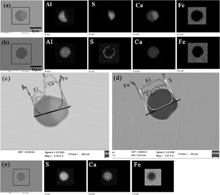
Element mapping and line scanning of typical calcium aluminates in slab (a) calcium aluminate with a oval CaS layer at outside; (b) calcium aluminate with a crescent-shaped CaS layer at outside; (c) element line scanning of inclusion (a); (d) element line scanning of inclusion (b); (e) CaS inclusion.
By summarizing the above analysis, schematic diagram of Al2O3 based inclusions transformation by calcium treatment in molten steel and during casting process is shown in Fig. 13, where the colors of inclusions represent for different inclusions types and the gradually varied color of (CaO)x·(Al2O3)y represents for the modification extents of calcium aluminates. So mechanism of inclusions transformation and formation can be described as:
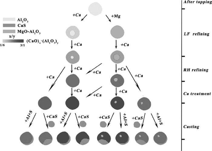
Schematic diagram of Al2O3 based inclusions transformation by calcium treatment in molten steel and during casting process.
(1) Al2O3 inclusion firstly was generated after tapping due to the reaction between massive dissolved oxygen in molten steel and Al alloy being added. Meanwhile, MgO and CaO in slag and refractory were reduced by Al to form dissolved Mg and Ca in molten steel respectively, which leaded to MgO–Al2O3 spinel inclusions and low modified calcium aluminates generated.
(2) MgO–Al2O3 spinel inclusions were gradually reduced by dissolved Ca from outside to inner to form MgO–Al2O3–CaO multi-component inclusions and low modified calcium aluminates were transformed towards calcium aluminates with higher CaO content during LF refining. The distribution of inclusions compositions was relatively dispersive in CaO–Al2O3–MgO ternary phase diagram at the end of LF refining.
(3) Because of the strong reaction of steel/ slag interface and well dynamic condition during RH refining, MgO–Al2O3–CaO multi-component inclusions and low modified calcium aluminates were further reduced by dissolved calcium to form better modified calcium aluminates (or containing less MgO–Al2O3 spinel). The distribution of inclusions compositions was relatively closer to the low melting region in CaO–Al2O3–MgO ternary phase diagram at the end of RH refining.
(4) After calcium treatment, calcium concentration was increased rapidly. Calcium aluminates were further modified into liquid ones. Besides, a small amount of lower modified calcium aluminates was likely to exist in molten steel.
(5) With the decrease of molten steel temperature and sulfur capacity of inclusions as well as chemical element segregation during casting process, a crescent-shaped CaS layer surrounding calcium aluminates (or containing less MgO–Al2O3 spinel) was generated by reaction between dissolved Al, S and modified calcium aluminates or diffusion of sulfur dissolved in inclusions from inner to surface. While a complex inclusion containing calcium aluminates and CaS was generated by collision or adsorption of calcium aluminates and directly CaS precipitation during casting process. In this case, the shape of CaS layer was close to oval.
3.6. Mechanism of Inclusions Deformation during Hot Rolling ProcessAccording to the above analysis, all the inclusions in hot rolled plates were almost from slab, where inclusions shape was mainly globular or near globular. However, various deformations have taken place for inclusions along the rolling direction during the hot rolling process. The variation of inclusions compositions with different sizes in slab showed that inclusions size tended to become larger with the increase of CaO content and the decrease of CaS content in multi-component inclusions according to Fig. 4(a). Wang et al.1) calculated the relationship between diameters of the inclusions in slab and the length of the inclusions in hot rolled plates and found they met the following equation:
| (19) |
Inclusions deformation extent during hot rolling process depends on the inclusions type, size, composition, etc. in slab. According to Eq. (19), the diameter of the inclusions in slab had significantly effect on the length of the inclusions in plates. Inclusions shape after hot rolling in plates fell into two broad categories based on their size. The size of first broad category was small and mainly less than 20 μm in plates. There were three routes of deformation during the hot rolling based on formation styles of CaS and modification extents of calcium aluminates and their deformation mechanism could be shown in Fig. 14. The first route shows well modified inclusions could be well deformed along the rolling direction. The second route shows low modified inclusions containing a CaS layer with the shape of crescent seemed to be difficult to be deformed. The third route shows a CaS layer with the shape of oval associating with low modified calcium aluminates could separate from the oxide core and even generate a CaS based tail behind the inclusion along the rolling direction.
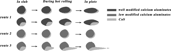
Deformation mechanism of small size inclusions with various modified calcium aluminates.
The size of second broad category was larger and mainly more than 50 μm in plates. Three routes of deformation were found based on formation styles of CaS and modification extents of calcium aluminates during the hot rolling and their deformation mechanism could be shown in Fig. 15. The first route shows C3A+C12A7 based inclusions were easier to continuously deform during hot rolling and their shapes looked smooth and continuous. The second route shows C3A+C12A7 based inclusions containing CaS and spinel could be divided into several parts by CaS and spinel particles and the detailed deformation process could be explained as follows: First, the composition of multi-component inclusions in slab was C3A+C12A7, CaS and spinel. Second, low melting point C3A+C12A7 was easily deformed and growed up while high melting point CaS and spinel particles were difficult to be deformed resulting in being crushed under the powerful rolling force. Finally, as the rolling process went on, C3A+C12A7 part further growed up and was divided into several parts by CaS and spinel particles in certain time, which made inclusions string in plate. The third route shows C12A7+CA based inclusions containing CaS and spinel could also be divided into several parts by CaS and spinel particles and looked like string, but the shape of C12A7+CA parts was more irregular than the C3A+C12A7 parts of route 2.
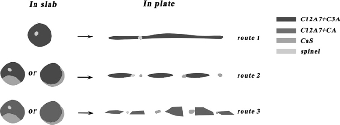
Deformation mechanism of large size inclusions with well modified calcium aluminates.
The formation mechanism of Al2O3–CaS based inclusions in Al-killed steel was studied by industrial trials and thermodynamic calculations, and the deformation mechanism of inclusions with various modification extents and different sizes during hot rolling was proposed. The following conclusions are obtained.
(1) The activities of CaO and Al2O3 of various calcium aluminates are expressed as a function of CaO and Al2O3 of CaO–Al2O3 inclusions respectively by the third liner fitting equation obtained by fitting with these results from different researchers.
(2) Before calcium treatment, there are two routes of oxide inclusions transformation process: the first route is Al2O3→MgO–Al2O3 spinel→MgO–Al2O3–CaO multi-component inclusion and the other is Al2O3→low modified calcium aluminates→better modified calcium aluminates.
(3) During RH refining, MgO–Al2O3–CaO multi-component inclusions and various modified calcium aluminates are further transformed into better modified calcium aluminates and their distribution in CaO–Al2O3–MgO phase diagram relatively closer to the low melting region at the end of RH. After calcium treatment, various modified calcium aluminates are further modified into liquid ones. Besides, a small amount of lower modified calcium aluminates is likely to exist in molten steel.
(4) With the decrease of molten steel temperature and chemical element segregation during casting process, massive Al2O3–CaS based inclusions were generated in slab. There are two formation manners for them based on the shape of CaS layer: 1) CaS layer with the shape of crescent surrounding calcium aluminates is generated by reaction between dissolved Al, S and modified calcium aluminates or diffusion of S dissolved in inclusions; 2) CaS layer with the shape of oval associated with calcium aluminates is generated by collision or adsorption of calcium aluminates and directly the precipiated CaS.
(5) For small size inclusions in plates, well modified inclusions are deformed very well along with the direction of hot rolling even if they are associated with a CaS layer, while low modified inclusions with the shape of crescent seem to be difficult to be deformed. However, If low modified inclusions contain a CaS layer with the shape of oval, the CaS layer can separate from the oxide core and even generate a CaS based tail behind the inclusion along the rolling direction.
(6) For large size inclusions in plates, three routes of deformation were found based on their modification extents and components: 1) C3A+C12A7 based inclusions are easier to continuously be deformed during hot rolling and their shapes are looked smooth and continuous; 2) C3A+C12A7 based inclusions containing CaS and spinel can be divided into several parts by CaS or spinel and looked like string; 3) C12A7+CA based inclusions containing CaS and spinel can also be divided into several parts by CaS or spinel and looked like string, but the shape of C12A7+CA part is more irregular than the C3A+C12A7 part of route 2.