Abstract
It is considered that the martensitic transformation in austenitic stainless steel is responsible for its high fracture toughness. A mechanism for fracture mechanical characteristics in the steel at higher rate of deformation might become quite complicated because a quick temperature rise may suppress the martensitic transformation as well as thermal softening. An investigation on fracture-mechanical characteristics of austenitic stainless steel at the higher rate and its rate sensitivity is indispensable. Recently, J-integral of 304 austenitic stainless steel is determined by three-point bending tests at various deflection rates. However, the tests carried out on small specimens might derive some errors for its evaluation because the plane strain condition is not ensured for J-integral. Additionally, the validity of the measured J-integral is not confirmed by other fracture parameters and it is obvious that measured value does not become a critical value of J-integral. In this study, J-integral of the steel is evaluated at different deflection rate by three-point bending tests on larger specimens. As a result, a higher value of J-integral is obtained compared with previous investigation on smaller specimens at the same normalized deflection rate. Additionally, the results indicates that the relationship between value of J-integral and normalized deflection rate is roughly a linear function in a semi-logarithmic plot in the range of normalized deflection rate from 4×10⁻⁴ to 10.5/s. The obtained values of the stretch zone width (SZW) are suitable for observation of a positive rate sensitivity of J-integral. Thus, the validity of the results for J-integral is confirmed.
1. Introduction
Austenitic stainless steel is used popularly in industries such as housewares, piping, and vessels because of its excellent corrosion property. After solution-heat treatment, the steel has a fully metastable austenitic microstructure which can be transformed into martensite during an inelastic deformation process. This is proven to be responsible for outstanding mechanical properties such as high strength and excellent ductility in this steel.1,2) Some previous studies3,4) reported that the martensitic transformation in the steel is considered as an energy-dissipative mechanism occurring at the crack tip of pre-cracked specimen. Thus, fracture toughness of austenitic stainless steel is improved by phase transformation, especially at cryogenic temperature which the transformation is well-promoted. Although many research works3,4,5,6,7) focus on fracture-mechanical characteristics of this steel, most of them are conducted at low deformation rate and the impact fracture characteristics have still studied insufficiently. Meanwhile, a mechanism for the impact performance at higher rate of deformation might become quite complicated8,9) because a quick temperature rise may suppress the transformation as well as a thermal softening phenomenon. An investigation on fracture-mechanical characteristics of austenitic stainless steel at a high velocity of loading and its rate sensitivity is indispensable.
J-integral defined by Rice10) is considered as elasto-plastic fracture toughness for the ductile materials. It is reported that the J-integral can be strongly correlated with equivalent fracture strain obtained from small punch tests.7,11,12) To obtain this correlation at room temperature, an equation for the relationship between J-integral and normalized deformation rate should be given. In the recent research works by Iwamoto et al.13) and Shi et al.,14) the rate sensitivity of fracture toughness in an austenite stainless steel is evaluated by bending tests carried out on relatively-small specimens. This might induce some errors for the evaluation of J-integral because the plane strain condition is not ensured for J-integral. Additionally, the validity of the measured J-integral was not confirmed by other fracture parameters and it might not become a critical J value because the geometry independence is not examined.
In the past, fracture characteristics of austenitic stainless steel have been experimentally examined by some researchers. The fracture toughness is evaluated by JIC, which is considered as a fracture criterion refers to crack initiation under plane strain condition, for a series of the steels by using three-point bending tests by Leal5) and Young,6) respectively. It is demonstrated that JIC is usually over 100 kJ/m2 and strongly depends on temperature due to effect of mechanically-induced martensitic transformation. Also, Samuel et al.15) report that fracture toughness of 316L austenitic stainless steel decreases with an increase in the testing temperature. Shindo et al.16) evaluate the fracture toughness of 304 and 316 austenitic stainless steel at cryogenic temperature in a high magnetic field by JIC. Some investigations17,18) report that JIC of the steel has a good relationship with value of stretch zone width (SZW). Furthermore, an enhancement of the fracture toughness in the relationship with the volume fraction of martensite transformed is discussed through the computational investigation by Iwamoto et al.3)
In this study, bending deformation behavior of pre-cracked specimens made of 304 austenitic stainless steel is investigated experimentally at various deflection rates. The three-point bending tests are conducted in quasi-static condition by an Instron-type conventional material testing machine and in impact loading condition by a drop-weight testing machine. Experimental procedures for the three-point bending tests are described in detail. Then, J-integral and SZW are determined from obtained testing data at different deflection rates for this steel. The deformation rate sensitivity of J-integral is discussed and compared with previous investigation.13) Finally, discussions on energy-absorption characteristic and its rate sensitivity in austenitic stainless steel are made.
2. Methodology
2.1. Specimen
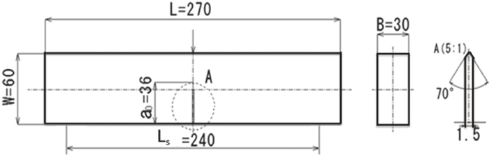
The pre-cracked specimens made of 304 austenitic stainless steel provided commercially are used. The dimensions of specimen obeyed the ASTM standard19) are shown in Fig. 1. L, B and W are the length, thickness and width of the specimen, respectively, ao is the initial crack length including both the fatigue pre-cracked and the machine notch length. Ls is the span length.
After machining, the specimens are heat-treated at 1323 K during 30 min in an electric furnace and then quenched into cold water. As a result, a microstructure of material with almost fully austenitic phase is obtained as shown in Fig. 2. The average of grain size is approximately 47 μm.
2.2. Determination of J-integral and Stretch Zone Width
The direct current potential drop method20) is applied to detect the onset of a crack extension. The output voltage is considered to relate directly to area of the crack extension, and the onset point of crack growth is defined by the point that the tendency of a change in the voltage. In this study, a different method with previous studies13,14) is applied to evaluate J-integral by following ASTM E182019) as,
|
J=
K
2
(
1-
ν
2
)
E
+
2
A
pl
B(
W-
a
o
)
| (1) |
where
E is Young’s modulus,
ν is Poisson’s ratio. They are 193 GPa and 0.333 for this material, respectively.
Apl is the plastic component of area under force-deflection curve until the onset point of crack extension.
K is stress-intensity factor and calculated as,
|
K=
F
L
s
B
W
3/2
×
3
(
a
o
W
)
1
2
[
1.99-(
a
o
W
)
(
1-
a
o
W
)
(
2.15-3.93(
a
o
W
)
+2.7
(
a
o
W
)
2
)
]
2(
1+2
a
o
W
)
(
1-
a
o
W
)
3
2
,
| (2) |
where
F is external force.
Ls,
B,
W, and
ao are the dimensions of specimen.
The surface of a haft of the pre-cracked specimen after bending deformation is observed by a fractographic analysis taken by a scanning electron microscope (SEM, JEOL, JSM-6510). At relatively-higher magnifications of an image, the stretch zone region exhibits a typical featureless appearance which is easily distinguishable from the region of the fatigue pre-crack or fracture surface.21)
2.3. Experimental Apparatus
The fatigue test for introducing the fatigue pre-crack of specimen is conducted by a fatigue testing machine (Shimadzu Servopulser E200kN). The force is controlled in the range from 1 to 16.5 kN and repeated 107 cycles. The limit of upper frequency is 30 Hz based on JIS T0310 standard.
The quasi-static three-point bending test is conducted by an Instron-type conventional material testing machine (Shimadzu AG-X250KN). The deflection rate is controlled by using constant crosshead speeds of 0.01, 0.1, 1, 10 mm/s. Deflection is obtained by measuring the displacement of the crosshead of the testing machine.
The impact three-point bending test is carried out by a drop-weight method. In the test, a weight with a mass of 140 kg is freely fallen from a height of 400, 450 and 550 mm. A force sensing block is installed under the center of the jig as same method proposed by Chuman et al.22) to capture the impact force for longer time by protection of the reflected wave propagating back into the force sensing part. Two strain gages (Kyowa KFG-1-350-D16-11) are glued axisymmetrically at the center of the force-sensing projection and connected with a Wheatstone bridge box by four-active method. The oscillations of voltage signals are filtered by a low-pass filter (NEC San-ei 9B02) before connecting to a digital oscilloscope (Yokogawa DL-1540) via signal conditioner (Kyowa CDV-700A) to amplify the output signals. A system including two optical fiber sensors (Keyence FU-77V) and amplifiers (Keyence FS-V31 and 32) is used to measure the velocity of the weight just before hitting the specimen. Deflection during impact deformation with respect to time is obtained by a high-speed camera (Photron Fastcam-512PCI32K). A linear magnetic scale system is applied to record the displacement of the weight. The deflection rate is calculated from the deflection-time curve by the finite difference method.
3. Results and Discussion
In order to provide easy understandings on the results, the obtained values of external force, deflection, and deflection rate are normalized. The value of measured external force F is normalized as the ratio of the maximum bending stress at the middle of the specimen to the 0.2% proof stress at room temperature σ0.2.
Measured deflection d and the deflection rate
d
˙
are normalized by the width of specimen and span length. They are expressed in the following equation
|
F
n
=
6F
L
s
B
W
2
σ
0.2
,
d
n
=
4Wd
L
s
2
,
d
˙
n
=
4W
d
˙
L
s
2
,
| (3) |
where
Fn is normalized force,
dn and
d
˙
n
is normalized deflection and normalized deflection rate, respectively. Value of
σ0.2 is 292 MPa obtained by a preliminary tensile test. The normalized deflection rates obtained by the quasi-static tests are approximately 4×10
−5, 4×10
−4, 4×10
−3, and 4×10
−2/s. The obtained maximum normalized deflection rate is approximately 7, 8.5, and 10.5/s in the drop-weight impact tests. In the following discussion, they are used as representative values of normalized deflection rate. For pre-cracked specimens, the determination of the dependence of strain rate on
σ0.2 using for the normalization of force in three-point bending deformation mode is relatively complicated. Moreover, the normalized force-normalized deflection curve is not used directly for the calculation of
J-integral. Therefore, value of
σ0.2 at room temperature independent on strain rate is used in this study.
Figure 3 shows force-deflection curve and the change in output voltage signals with respected to deflection at normalized deflection rate of 4×10⁻² and 10.5/s in quasi-static and impact conditions, respectively. As can be seen from this figure, the tendency of output voltage signals clearly changes when the crack begins extending and the onset point of crack extension is determined. Tendency of the change in the voltage is different from that in the investigation of Iwamoto et al.13) because of a difference in the size of specimen. Deflection at the onset of crack extension in quasi-static test and impact test is 12.7 and 12.6 mm, respectively. The deflection in the quasi-static condition is larger than that of previous study13) at the same normalized deflection rate.

Figure 4 shows the normalized force-normalized deflection curve at the different normalized deflection rates. In this figure, circular marks mean the onset point of crack extension at each condition. Although output signals are filtered by the low-pass filter, their small oscillations in drop-weight tests can be observed in this figure. In drop-weight impact tests, the normalized deflection at the onset point of crack extension is higher than that at the maximum normalized force.

Figure 5 shows the values of normalized force and normalized deflection at the onset of crack extension with respected to normalized deflection rate in a semi-logarithmic plot. In general, at the onset point of crack extension, normalized force increases with an increase in the normalized deflection rate. This result can be explained from the viewpoint of the hardening effect at higher deformation rate. At the same time, almost same values of normalized deflection are obtained for different cases of normalized deflection rate, except for 4×10⁻⁵/s. This observation is clearly different from that in investigation of Iwamoto et al.13) which shows a significant increase of deflection at the onset of crack extension in impact tests.

From the obtained results, J-integral is calculated by using above-mentioned equation. The amplitude of oscillation in drop-weighted impact tests seems to be similar and signals of oscillation nearly are sinusoidal as shown in Fig. 4. Thus, J-integral is calculated from the area below force-deflection curve including the oscillation and the amplitude of the oscillation is not evaluated as an error. Figure 6 shows value of J-integral with respected to the normalized deflection rate in a semi-logarithmic plot until the onset point of crack extension of specimens. Here, the semi-logarithmic plot is used instead of full-logarithmic one to see the rate sensitivity more clearly and discuss on rate sensitivity of J-integral easily. In addition, this kind of presentation makes easier comparisons with other studies. Obviously, at a higher normalized deflection rate, type 304 austenitic stainless steel indicates a higher value of J-integral. A positive rate sensitivity of J-integral can be seen from quasi-static to impact deformation. From this figure, the relationship between value of J-integral and normalized deflection rate is roughly a linear function in a semi-logarithmic plot in the range of investigated normalized deflection rate except for the case of 4×10⁻⁵/s as
|
J=42.341ln(
d
˙
n
)
+1 496.7 (
kJ/
m
2
)
|
However, temperature rise in the material at relatively-higher deflection rate due to adiabatic heating by the inelastic irreversible work may induce the thermal softening effect. This can attribute on the characteristic of the normalized force-normalized deflection curve as well as the onset point of crack extension. Therefore, this logarithmic function in the relationship between value of J-integral and normalized deflection rate might not be assured at a relatively-higher normalized deflection rate. Furthermore, since value of J-integral is related to the value of normalized deflection at the onset point of crack extension, J-integral increases when onset point is delayed.
Figure 7 shows a photograph of the microstructure for the determination of SZW at normalized deflection rate of (a) 4×10⁻³/s under quasi-static deformation and (b) 7/s under impact loading deformation. A considerably lower value in the SZW can be seen in case of 4×10⁻³/s compared with that at normalized deflection rate of 7/s. The value of SZW is 245 μm and 600 μm, respectively.

The relationship between values of the SZW and normalized deflection rate in a semi-logarithmic plot is shown in Fig. 8. Here, the SZW is normalized by the average grain size of original material. A linear function for this relationship can be observed. In drop-weight impact tests, obtained values of SZW are significantly higher than that in quasi-static tests. This result is suitable for the observation of the positive rate sensitivity in J-integral from quasi-static to impact deformation as above-discussions since it is considered that the SZW is strongly associated with a crack initiation. Moreover, the validity of results for the rate sensitivity of J-integral can be confirmed.

Figure 9 shows a comparison of the rate sensitivity of J-integral between previous13) and present studies measured by the same method to normalize the deflection rate and calculate the J-integral. The sizes of the specimen in the previous and present investigation are different. From the Fig. 9, the rate sensitivity of J-integral in both studies is similar. In impact tests, values of J-integral in present study are slightly lower than those in previous one because the normalized deflection rates in this investigation are lower. However, a higher value of J-integral can be seen in present investigation compared with previous one at the same normalized deflection rate in quasi-static condition. This can be explained by a difference in the size of specimen. As above discussion, some errors for evaluation of J-integral can be induced in previous study because the plane strain condition is not ensured for J-integral as well as heat capacity related to the thermal softening behavior.

Since energy dissipated during the inelastic deformation induces the delay of crack extension, energy absorption of the material is considered to indicate a strong relationship between external force and deflection as well as the crack initiation. In addition, J-integral is related to the difference in energy absorbed during deformation by specimens with an incrementally-increase in a crack length. Consequently, an evaluation of the energy absorption is equivalent to a measurement of J-integral. From the obtained results, it can be inferred that the studied austenitic stainless steel indicates better performance of absorbing energy at a higher normalized deflection rate. A positive rate sensitivity of energy absorption is observed from quasi-static to impact loading deformation.
Although fracture characteristics of this austenitic stainless steel can be determined in experiment, the mechanism for the high performance in impact condition is still unclear. In general, the temperature increases with an increase in the deformation rate. A relatively high temperature might be induced in impact deformation. The higher temperature rise concentrates in a small region near the crack-tip and promotes a localization of deformation at high rate of deformation. Moreover, martensitic phase might be formed in the region surrounding the higher temperature region and thus the work hardening is improved. As a result, the fracture toughness of austenitic stainless steel increases with increasing the deformation rate as experimental investigation in this study. Because of the limitation of the experiments, computational simulation and an evaluation of fracture toughness by a path integral are necessary for further investigations.
4. Concluding Remarks
In this study, the bending deformation behavior of pre-cracked specimens made of type 304 austenitic stainless steel is investigated at various deflection rates in quasi-static and drop-weight impact tests. J-integral and the SZW are evaluated and then, energy absorption of this steel is discussed. Concluding remarks can be introduced as following.
(1) The steel indicates a positive rate sensitivity of J-integral from quasi-static to impact deformation expressed with a logarithmically-linear function. The obtained values of the SZW, which show significantly higher values in impact drop-weight tests, are suitable for observation of a positive rate sensitivity of J-integral. The validity of the results for J-integral is confirmed.
(2) A higher value of J-integral can be seen in present investigation compared with previous one at the same normalized deflection rate because of a difference in the size of specimen. Some errors for evaluation of J-integral by using relatively-small specimens may be induced in previous study since the plane strain condition is not ensured for J-integral as well as heat capacity related to the thermal softening behavior.
(3) Energy-absorption characteristic of this austenitic stainless steel can be discussed on the basis of the results for J-integral and the SZW. At a higher normalized deflection rate, this steel possesses better energy absorption characteristic and a positive rate sensitivity of energy absorption is observed from quasi-static to impact loading deformation.
Acknowledgements
We gratefully acknowledge financial supports from the 23rd ISIJ Research Promotion Grant provided by the Iron and Steel Institute of Japan. We wish to thank Mr. Johguchi of Mitsui Chemicals, Inc., Mr. Hashimoto of Webasto Japan Corporation and Ms. Shi of Ondo Corporation for their assistances with the experimental investigation.
References
- 1) Y. Tomita and T. Iwamoto: Int. J. Mech. Sci., 37 (1995), 1295.
- 2) T. Iwamoto, T. Tsuta and Y. Tomita: Int. J. Mech. Sci., 40 (1998), 173.
- 3) T. Iwamoto and T. Tsuta: Int. J. Plast., 18 (2002), 1583.
- 4) S. D. Antolovich and B. Singh: Metal. Trans., 2 (1971), 2135.
- 5) R. H. Leal: MIT, 1984, Ph.D. thesis.
- 6) C. C. Young: MIT, 1988, Ph.D. thesis.
- 7) Y. Shindo, K. Horiguchi, T. Sugo and Y. Mano: J. Test. Eval., 28 (2000), 431.
- 8) T. Iwamoto, M. Cherkaoui and T. Sawa: Int. J. Mod. Phys. B, 22 (2008), 5985.
- 9) S. Yamanaka, T. Iwamoto and T. Sawa: Mater. Res. Innov., 15 (2011), 131.
- 10) Z. R. Rice: J. Appl. Mech., 35 (1968), 379.
- 11) T. Misawa, S. Nagata, N. Aoki, J. Ishizaka and Y. Hamaguchi: J. Nucl. Mater., 169 (1989), 225.
- 12) X. Mao and H. Takahashi: J. Nucl. Mater., 150 (1987), 42.
- 13) T. Iwamoto, S. Hashimoto, T. Kawabata and L. Shi: Tetsu-to-Hagané, 99 (2013), 322 (in Japanese).
- 14) L. Shi, T. Iwamoto and S. Hashimoto: Eng. Trans., 61 (2013), 119.
- 15) K. G. Samuel, O. Gossmann and H. Huthmann: Int. J. Pres. Ves. Pip., 41 (1990), 59.
- 16) Y. Shindo, Y. Yamaguchi and K. Horiguchi: Cryogenics, 44 (2004), 789.
- 17) T. Torimaru, M. Sugiyama, M. Itatani and M. Koshiishi: Trans. JSME Ser. A, 79 (2013), 702 (in Japanese).
- 18) C. V. Hyatt and J. R. Matthews: Int. J. Fract., 66 (1994), 19.
- 19) ASTM E1820-13e1, Standard Test Method for Measurement of Fracture Toughness, ASTM International, West Conshohocken, PA, (2013), http://www.astm.org, (accessed 2013-12-11).
- 20) G. A. Hartman and D. A. Johnson: Exp. Mech., 27 (1987), 106.
- 21) J. R. Tarpani, W. W. Bose and D. Spinelli: Mater. Charact., 51 (2003), 159.
- 22) Y. Chuman, K. Minuras, K. Kaizu and S. Tanimura: Int. J. Impact Eng., 19 (1997), 165.