Abstract
The shroud nozzle is used to transport the molten steel from the ladle to the tundish in the continuous casting process. A hydraulic manipulator transfers the shroud nozzle and connects it to the collector nozzle installed on the bottom of the ladle. During the nozzle connection, however, the misalignment between the shroud nozzle and the collector nozzle frequently occurs due to the initial position error of the ladle, unexpected external forces on the nozzle, etc. In case the nozzle is not aligned properly, there is air-inflow into the molten steel through the crevice, and this results in the defect of steel products by oxidation. In addition, if the nozzle tightening force is not enough to hold the shroud nozzle while the molten steel flows into the nozzle, the nozzle vibration occurs by the irregular flow of the molten steel and it gives rise to another air-inflow to the molten steel. POSCO currently uses the remote operated manipulator for the shroud nozzle manipulation, but this cannot measure and control a fine nozzle alignment appropriately.
In this paper, we designed and controlled a novel 5-DOF hydraulic manipulator to solve the nozzle misalignment problem. Each joint of the manipulator contains a torque sensor which enables to detect the external forces exerted to the shroud nozzle, and this is utilized to measure the misalignment. Moreover, the nozzle misalignment can be adjusted in real-time by the proposed force integral controller using joint torque sensors.
1. Introduction
In recent decades, a robotic system has been spread in various industrial fields for the realization of automation. The use of versatile automated robotic facility leads to reduction of manufacturing costs, product quality increase, productivity growth, and the prevention of safety accident. Automated manipulators also can be used widely in steel manufacturing instead of human operations, because there are a lot of harsh circumstances in the plants such as the heavy iron products handling, limited working spaces, high temperature, dusts, etc.1,2,3,4)
In general, the continuous casting of molten steel is the process of making semi-finished products such as slab, bloom, and billet. The surroundings in continuous casting processes are sometimes perilous for workers, because the molten steel might be dispersed toward workers. Hence, manipulators that can replace the human operation in dangerous workplaces are required. For instance, manipulators can be used at temperature detecting, molten steel sampling, inserting mold flux, nozzle opening and cleaning, and shroud nozzle manipulation, etc.
Due to the advances in steel making technology, the shroud nozzle in the middle of the continuous casting processes is used between the ladle and the tundish or between the tundish and the mold in order to guide of the molten steel flow. It prevents the oxidation of the molten steel and the occurrence of slag inclusion, which are caused by the vortex flow of the molten steel. Thus, the nozzle operations can affect the quality of steel products.5)
The oxidation, however, can occur while the molten steel is poured from the ladle to the tundish, though the shroud nozzle guides the flow of steel. The main reason is the nozzle misalignment between the collector nozzle on the bottom of the ladle and the shroud nozzle. The ladle movement by the remote operation generates initial position errors of the collector nozzle, and it gives rise to the nozzle misalignment between the shroud nozzle and the collector nozzle. In this case, due to the incomplete airtightness, the air-inflow into the crevice between two nozzles occurs and it causes the oxidation of the molten steel. The oxygen is combined with the steel, and this creates a steed oxide of AL2O3 and oxidative inclusions, which causes the defect on steel plate in Fig. 1. Besides, oxidative inclusions often adhere on the inner wall of the nozzle and cause nozzle clogging. Even though there is no initial nozzle alignment error, the misalignment could arise because of the flow of molten steel in tundish. Then air-inflow between nozzles occurs and the oxidation of molten steel would follow. Furthermore, the non-uniform molten steel flow generates the vibrations when it passes through the shroud nozzle. The vibration makes tiny spiracles between the collector nozzle and shroud nozzle. Thus the manipulator should be controlled against the nozzle fluctuation by the molten steel flow.
In this paper, we propose the 5-DOF hydraulic manipulator to solve the nozzle misalignment problem described above. It enables to maintain the airtightness against the initial position error of the nozzle and the misalignment caused by disturbances, which are arisen by the molten steel flow. In the manipulator, the force integral control is performed by using torque sensors at each joint, where all directional forces on the nozzle should be identical to get rid of the vertical nozzle misalignment.
The rest of this paper is organized as follows: The shroud nozzle manipulation process is described in section 2. The design of a hydraulic manipulator and control algorithms are expressed in section 3. The control algorithm section consists of the torque output controller design and the force integral controller design. Simulation and experimental results verify the capability of the manipulator in section 4, and the conclusion is given in section 5.
2. Shroud Nozzle Manipulation
In the continuous casting process, the molten steel is carried from the ladle to the mold. The liquid-type molten steel in the ladle passes through the tundish and reaches to the mold to be solidified. The ladle is the container of molten steel in Fig. 2, and handled by a hydraulic powered ladle turret. The tundish is an intermediate container that stabilizes the liquid type molten steel and sends it to the mold. On the bottom of the ladle, there is a collector nozzle for discharging the molten steel to the tundish. If there is no connection medium between the collector nozzle and the tundish, the flow of molten steel has large contact area with oxygen in the air, and it causes the oxidation of the steel product.
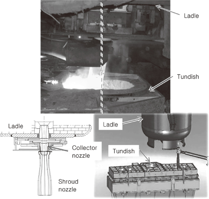
The ladle turret that holds the ladle stops on top of the tundish, then the shroud nozzle is transferred from the home position and connected to the collector nozzle. If the shroud nozzle is not completely aligned with the collector nozzle like the photograph in Fig. 2, air inflow occurs in the crevice between the collector nozzle and shroud nozzle.
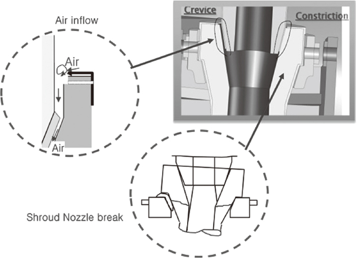
Figure 3 explains the problems when the shroud nozzle is not aligned correctly. The molten steel flow pressure induces the influx of atmospheric oxygen through the gap in the nozzle joint, and the oxygen causes the re-oxidation of the molten steel as described in chapter 1. In the worst case, the upper part of shroud nozzle cracks when the molten steel passes through the misaligned shroud nozzle for a while in Fig. 3. If mechanical stress of weak points is increased due to the flow of heavy specific gravity of the molten steel and exceeds the maximum strength of the shroud nozzle, the shroud nozzle is finally destroyed, and it causes a disastrous result as the dispersion of the molten steel.
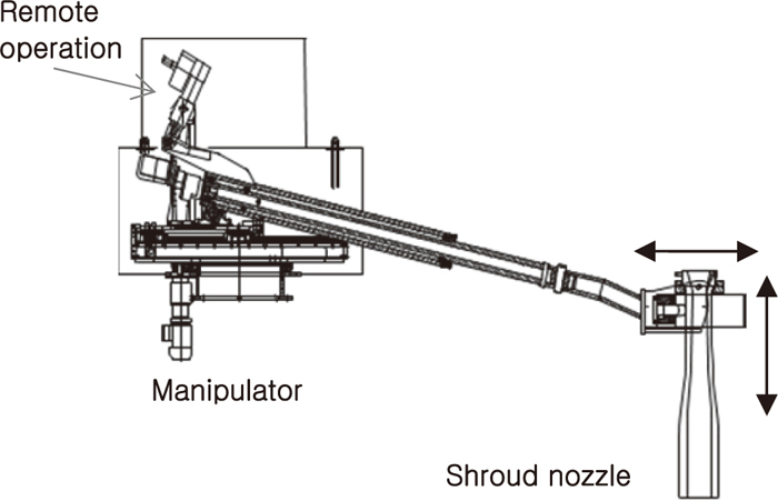
The hydraulic powered manipulator in Fig. 4 is currently used for the shroud nozzle manipulation in POSCO. The manipulator is manually operated by the remote control. It transfers the shroud nozzle from the deck and combines it to the collector nozzle. However, it has several problems in nozzle connections. For instance, no optical sensors and electronic devices are available at the end-effector of the manipulator, because circumstances around the nozzle are very harsh. In addition vision type sensors may not be applied, because circumstances around nozzles are quite inadequate to use vision sensors by interferences of temperature and steel dusts. Therefore remote operators of the manipulator should rely on only their naked eyes in the distance. Moreover, though the sensor detects the nozzle’s alignment error, there is no method to control the nozzle position in real-time.
In order to measure and control the alignment in real-time, we developed a new hydraulic manipulator. It enables to measure external forces at the end of shroud nozzle by using joint torque sensors. This principle makes possible to maintain proper nozzle alignment by controlling the nozzle position accurately.
3. Design and Control of Shroud Nozzle Manipulator
This chapter introduces the design and control of a new hydraulic manipulator for the shroud nozzle manipulation. Unlike the conventional manipulator used in POSCO, a new 5-DOF hydraulic manipulator can measure the reaction forces by joint torque sensors and LVDTs and control the position of the shroud nozzle precisely.
3.1. Hydraulic Manipulator Design
The motor based manipulators have been commonly used in many industries up to now due to its good controllability. But it has several drawbacks such as bulkier size, reduction of speed by harmonic gears, vibrations, complex electronics, limited acceleration, gear backlash, etc. Also, the growth of robot system size to handle high payload might cause interference with other facilities due to the limited space in the factories. Compared to the same-sized electric motor manipulators, however, the hydraulic manipulators can generate much higher torque and peak acceleration with relatively simple structure. Therefore, the hydraulic manipulators are more suitable to be installed in the steel plant where it requires high power in the limited working space.6)
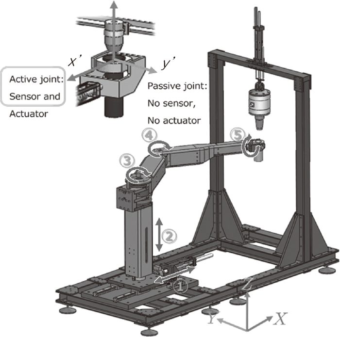
Figure 5 shows a photograph of the multi-DOF shroud nozzle hydraulic manipulator, which was developed in half scale of the real manipulator for the laboratory test. Three rotary and two linear hydraulic actuators, which are suitable to align the collector nozzle and the shroud nozzle, compose 5-DOF motion mechanism. Each rotary joint includes joint torque sensors and encoders, and linear links contain the linear variable differential transformers (LVDT) and load cells. The torque sensors and force sensors measure the external forces when the nozzles are connected.

Figure 6 shows the schematic view of the shroud nozzle manipulator which represents the joint actuations. Hydraulic rotary actuators are used in the joint ③, ④, and ⑤ and hydraulic linear actuators are used in the joint ① and ②. The movements in xy-plane are generated by the joint combination of ①, ③, and ④ while linear actuator ② is used in z direction motion, which is the source of the nozzle tightening force. A part yawing motion at the end-effector is controlled by the rotation of ⑤ and used when the manipulator pick the shroud nozzle. The specification of manipulator’s joint actuators is presented in Table 1.
Table 1. Specification of the actuators.
| Motion | Act. | T/F (Nm/N) | Arm (m) | Total load (Kg) | Stroke |
|---|
| 1. X | Linear | 1500 N | | 150 | 0.3 m |
| 2. Z | Linear | 1500 N | | 250 | 0.3 m |
| 3. Slewing | Rotary | 4000 Nm | 2 | 200 | 120° |
| 4. XY | Rotary | 1200 Nm | 1 | 120 | 100° |
| 5. Yawing | Rotary | 200 Nm | 0.2 | 100 | 120° |
In order to simulate the movement of the ladle, an alternative miniature collector nozzle simulator was fabricated on the manipulator frame as shown in Fig. 5. Since the shroud nozzle manipulator cannot measure the actuation forces by itself, the collector nozzle simulator contains 3-axis force gauging sensor. The nozzle tightening force generated from the manipulator is detected by the gauge in z and the nozzle alignment can be measured in x- and y-direction gauges.
3.2. Control
This section introduces the torque output control and force control algorithm for the shroud nozzle manipulator. The torque output controller for a hydraulic rotary actuator generates a desired torque output to control output forces of the manipulator. The force controller in the shroud nozzle manipulator performs compliant control, force integral control, and joint impedance control for a vertical nozzle alignment and generating appropriate nozzle tightening forces.
3.2.1. Torque Output Control
The shroud nozzle manipulator includes three hydraulic rotary actuators. Small size, lightweight, high torque and high power are advantages of the hydraulic actuators. Three rotary actuators used in the manipulator are the double-vane type.7,8,9) Figure 7 illustrates the schematic view of a double vane rotary actuator. Vane type hydraulic motors have a simple design and less variation of output torque. In addition, forward and reverse rotations are smoothly available. Since pressures acting on the rotor equally maintain the balance, the bearing load is small.
Dynamic equations of double vane rotary actuator are derived. The compressibility of oil and the vane leakage are considered. The rotary actuator’s volume of vane is as follows:
|
V
m
=
L
D
v
R
2
=
D
v
R,
| (1) |
where
L=2, because the actuator has dual vanes.
Dv is a volumetric displacement.
R is the maximum stroke of the rotary actuator. Compression flow dynamics in chamber
A and
B are described by
|
P
˙
A
=
β
V
m
+L
D
v
θ
(
Q
A
-L
D
v
θ
˙
-
q
l
),
| (2) |
|
P
˙
B
=
β
V
m
+L
D
v
θ
(-
Q
B
+L
D
v
θ
˙
+
q
l
),
| (3) |
where
P
˙
A
and
P
˙
A
are the compressibility of oil and the flow rates to the chamber of
A and
B are represented as
QA and
QB, respectively.
θ is the rotation angle of the rotor and
β is the effective bulk modulus. Assuming a laminar flow, leakage across the vane is expressed by
|
q
l
=
R
v
(
P
A
-
P
B
)=
R
v
ΔP,
| (4) |
where
Rv=3.575×10
−9m3/
s/
Nm−2 is the leakage coefficient of rotary actuator. From (2) and (3), the torque equation is obtained as follows,
|
τ=L
D
V
(
P
A
-
P
B
).
| (5) |
|
τ
˙
=
E
+
(
Q
A
+
Q
B
)-
E
-
(
Q
A
-
Q
B
)-
F
θ
θ
˙
-
G
τ
τ
| (6) |
|
E
+
=
L
D
υ
V
m
β
v
m
2
-
(L
D
υ
θ)
2
,
E
-
=
(L
D
υ
)
2
βθ
V
m
2
-
(L
D
υ
θ)
2
| (7) |
|
F
θ
=
2
V
m
β
(L
D
υ
)
2
V
m
2
-
(L
D
υ
θ)
2
,
G
τ
=
2
V
m
R
V
β
V
m
2
-
(L
D
υ
θ)
2
,
| (8) |
where
τ is the output torque and
θ
˙
is the link velocity. The equations of the flow are derived from the flapper nozzle servo valve dynamics as
|
Q
A
+
Q
B
=
K
sv
(
P
s
-
P
A
+
P
B
-
2F(i)
K
sv
i
)
i=
Q
+
i,
| (9) |
|
Q
A
-
Q
B
=
K
sv
(
P
s
-
P
A
-
P
B
)
i=
Q
-
i,
| (10) |
|
E
I
=
E
+
Q
+
-
E
-
Q
-
| (11) |
where
Ksv is the servo valve coefficient and the valve leakage is represented as
qleakage =
F(
i). The input current and input matrix related to the input flow rate with respect to the input current are expressed as
i and
EI, respectively. The torque generation model from
Eqs. (6),
(7),
(8),
(9),
(10),
(11) is summarized as the closed form:
|
τ
˙
=
E
I
(
P
A
,
P
B
,θ,i)i-
F
θ
θ
˙
-
G
τ
τ,
| (12) |
where
Fθ and
Gτ are the spring coefficient like function and the torque dynamics by internal leakage, which are defined in (8). The controller that regulates the torque output should be developed with the hydraulic actuator. This is based on the robust control against the model uncertainties. The hydraulic actuator model can be expressed as follows:
|
M
τ
˙
+Nτ+H
θ
˙
=
M
ˆ
τ
˙
+
N
ˆ
τ+
H
ˆ
θ
˙
+{(M-
M
ˆ
)
τ
˙
+(N-
N
ˆ
)τ+(H-
H
ˆ
)
θ
˙
}
=
M
ˆ
τ
˙
+
N
ˆ
τ+
H
ˆ
θ
˙
+{
M
˜
τ
˙
+
N
˜
τ+
H
˜
θ
˙
}
=
M
ˆ
τ
˙
+
N
ˆ
τ+
H
ˆ
θ
˙
+
i
w
=i,
| (13) |
where
iw includes the model uncertainty and external disturbance.
M=1/
EI,
N=
Gτ/
EI, and
H=
Fθ/
EI are defined from (12), respectively.
M
ˆ
,
N
ˆ
, and
H
ˆ
are the constant values in
Table 2. And the control input is set by the integral equation. When
iw=0,
|
ε
=
Δ
i
d
-(
M
ˆ
τ
˙
+
N
ˆ
τ+
H
ˆ
θ
˙
),
| (14) |
|
ε+κ∫
εdt
=
i
d
+κ∫
i
d
dt-κ(
M
ˆ
+
N
ˆ
∫
τdt+
H
ˆ
θ)
=
i
ref
,
| (15) |
|
i
ref
=
Δ
i
d
+κ∫
i
d
dt-κ(
M
ˆ
τ+
N
ˆ
∫
τdt
+
H
ˆ
θ)
i=
i
ref
-
i
u
,
| (16) |
where
ε represents the error term and the desired input and the reference input are denoted as
id and
iref, respectively.
iu is the auxiliary input to handle
iw. κ indicates the weight gain for the integral term. After plugging in a control input, the dynamic equation is described as
|
M
ˆ
τ
˙
+
N
ˆ
τ+
H
ˆ
θ
˙
=i-
i
w
=(
i
ref
-
i
u
)-
i
w
{
i
d
-(
M
ˆ
τ
˙
+
N
ˆ
τ+
H
ˆ
θ
˙
)}+κ∫
{
i
d
-(
M
ˆ
τ
˙
+
N
ˆ
τ+
H
ˆ
θ
˙
)}dt
=
i
u
+
i
w
.
| (17) |
Closed loop dynamics is presented as
|
s
˙
+κ∫
sdt
=
i
u
+
i
w
s
=
Δ
∫
{i
d
-(
M
ˆ
τ
˙
+
N
ˆ
τ+
H
ˆ
θ
˙
)}dt.
| (18) |
The pair (
s,
iw) is strictly passive when
iu=
Ks. And Lyapunov function candidate is
The time derivative of
V becomes as follows:
|
V
˙
=s
s
˙
=s(-κs+
i
u
+
i
w
)=-κ
s
2
+s
i
u
+s
i
w
=-κ
s
2
-(
K+
1
γ
2
)
s
2
+s
i
w
=-(κ+K)
s
2
-
1
γ
2
{
s
2
-
γ
2
s
i
w
+
γ
4
4
i
w
2
}+
γ
2
4
i
w
2
=-(κ+K)
s
2
-
1
γ
2
|
s-
γ
2
2
i
w
|
2
+
γ
2
4
|
i
w
|
2
≤-(κ+K)
s
2
+
γ
2
4
|
i
w
|
2
≤-
γ
1
(
| s |
)
+
γ
2
(
|
i
w
|
)
| (20) |
|
i
u
=
Δ
-(
K+
1
γ
2
)
s , where K≥0 and γ≥0
| (21) |
and
γ2 are the class
K∞ functions, thus it is the ISS (Input to State Stability) stable.
10) When
iw is bounded and
γ is sufficiently small, as
t → ∞
|
V→0,⇔s=∫
i
d
-(
M
ˆ
τ
˙
+
N
ˆ
τ+
H
ˆ
θ
A
)}dt→0
| (22) |
|
⇔
i
d
-(
M
ˆ
τ
˙
+
N
ˆ
τ+
H
ˆ
θ
A
)→0
| (23) |
And then, the modified dynamics and the desired input terms are expressed as
|
i
d
=
M
ˆ
τ
˙
+
N
ˆ
τ+
H
ˆ
θ
˙
,
| (24) |
|
i
d
=
Δ
M
ˆ
τ
˙
des
+
N
ˆ
τ
des
+
K
I
∫
(
τ
des
-τ)dt+
H
ˆ
θ
˙
.
| (25) |
Finally, the closed loop dynamics becomes
|
M
ˆ
(
τ
˙
des
-
τ
˙
)+
N
ˆ
(
τ
des
-τ)+
K
I
∫
(
τ
des
-τ)dt=0.
| (26) |
The torque output of the hydraulic actuator is supposed to be the desired value in process of time. This is used to control the output of hydraulic actuator and its performance is approved in section 4.
Table 2. Specification of actuator parameters.
| Parameters |
|---|
| L=2 |
M
ˆ
= 5.250×10⁻⁷ |
| Ps = 2.0×10⁷[Nm−2] |
N
ˆ
= 3.720×10⁻⁵ |
| Vm = 1.59835×10⁻³[m3] |
H
ˆ
= 2.930×10⁻³ |
| Dv = 7.6395×10⁻⁴[m3/rad] | Ki = 1.5×10⁻³ |
| β = 6.6×10⁶[Nm−2] | TS = 0.001 sec |
| RV = 3.575×10⁻⁹[m3/sec/Nm−2] | K=200 |
| Ksv = 6.15×10⁻⁵ | |
The purpose of force control is that the controller cancels out the desired forces (fx,des=0, fy,des=0) and generates the steady vertical tightening force (fz,des). For instance, the nozzle tightening force of 800 N is required to maintain the pressure of molten steel flow. The shroud nozzle which is held in the manipulator’s end-effector approaches to the collector nozzle by a position-based control algorithm due to the motion control in the free space. Just after the contact of two nozzles, the force control algorithm based on the force integral control is applied.10,11,12,13) The integral equation based controllers tend to reduce the error level in process of time and operate stably by considering the model dynamics. In addition, the force integral control is a kind of passivity-based control so that it is strong against model uncertainty and disturbance such as the external forces on the nozzle by unexpected movements of the molten steel. Depending on a desired input, the integral controller is applied for various force controllers. The manipulator dynamics is presented as follows:
|
τ+
J
T
(q)
f
ext
=M(q)
q
¨
+C(q,
q
˙
)
q
˙
+g(q)
| (27) |
where
τ is the system input, and
fext is the external force input from the collector nozzle. Equivalent D’Alambertian force is described by
|
τ=-(
J
T
(q)
f
ext
-M(q)
q
¨
-C(q,
q
˙
)
q
˙
-g(q))
| (28) |
The equivalent torque of the manipulator system is stated as,
|
τ
ext
=
J
T
(q)
f
ext
| (29) |
After the force of gravity is compensated, the force error is presented as,
|
ε
τ
=
Δ
τ
u
-
J
T
(q)
f
ext
+M(q)
q
¨
+C(q,
q
˙
)
q
˙
| (30) |
And the integral equation is derived as follows:
|
(
J
T
(q)
f
ext
-M(q)
q
¨
-C(q,
q
˙
)
q
˙
)
=
τ
u
+κ∫
(
τ
u
-
J
T
(q)
f
ext
)
dt+κ∫
(M(q)
q
¨
+C(q,
q
˙
)
q
˙
)dt
| (32) |
The control input is defined as follows:
|
τ
ref
=
τ
u
+κ∫
(
τ
u
-
J
T
(q)
f
ext
)
dt
+κ∫
(M(q)
q
¨
+C(q,
q
˙
)
q
˙
)dt
| (33) |
where
g(
q) is the gravity component. The closed-loop dynamics is derived as
|
(
τ
u
-
J
T
(q)
f
ext
+M(q)
q
¨
+C(q,
q
˙
)
q
˙
)
+κ∫
(
τ
u
-
J
T
(q)
f
ext
+M(q)
q
¨
+C(q,
q
˙
)
q
˙
)dt=0
| (35) |
When
t goes to the infinity, the equation is
|
τ
u
-
J
T
(q)
f
ext
+M(q)
q
¨
+C(q,
q
˙
)
q
˙
=0
| (36) |
The input of the force controller is constituted as follows,
|
τ
ref
=
Δ
τ
u
+κ∫
(
τ
u
-
J
T
(q)
f
ext
)dt
+κ(
M(q)
q
˙
-
1
2
∫
(
M
˙
(q,
q
˙
)
q
˙
)dt
)
| (37) |
Desired control inputs for manipulation are presented. First, the task space virtual-spring-damper (VSD) control, which is the position based compliant control method, was performed for the shroud nozzle to approach toward the collector nozzle. Its parameters are presented in
Eq. (40).
|
τ
u
=
J
T
{-
D
F
(
p
˙
des
-
p
˙
)-
K
F
(
p
des
-p)}+
D
τ
q
˙
| (39) |
|
D
F
=[
100
0
0
0
50
0
0
0
50
] ,
K
F
=[
0.5
0
0
0
10.0
0
0
0
0.05
] ,
D
τ
=[
0.05
0
0
0
0
0.05
0
0
0
0
80.5
0
0
0
0
80.5
]
| (40) |
Second, the task space integral force control is used, after contacting the collector nozzle and shroud nozzle.
|
τ
u
=
J
T
(
f
des
+
D
F
p
˙
)+
D
τ
q
˙
| (41) |
|
D
F
=[
0.5
0
0
0
0.5
0
0
0
300
] ,
D
τ
=[
100.5
0
0
0
0
0.05
0
0
0
0
0.05
0
0
0
0
0.05
]
| (42) |
4. Simulations and Experiments
To validate the torque output controller derived in section 3, the simulation and experiment of 1-dof hydraulic actuator were performed. Based on the 1-dof actuator experiments, the 5-dof shroud nozzle manipulator’s simulation model was established and its force controller was implemented in the miniature shroud nozzle manipulator.
4.1. 1-dof Torque Output Controller Test
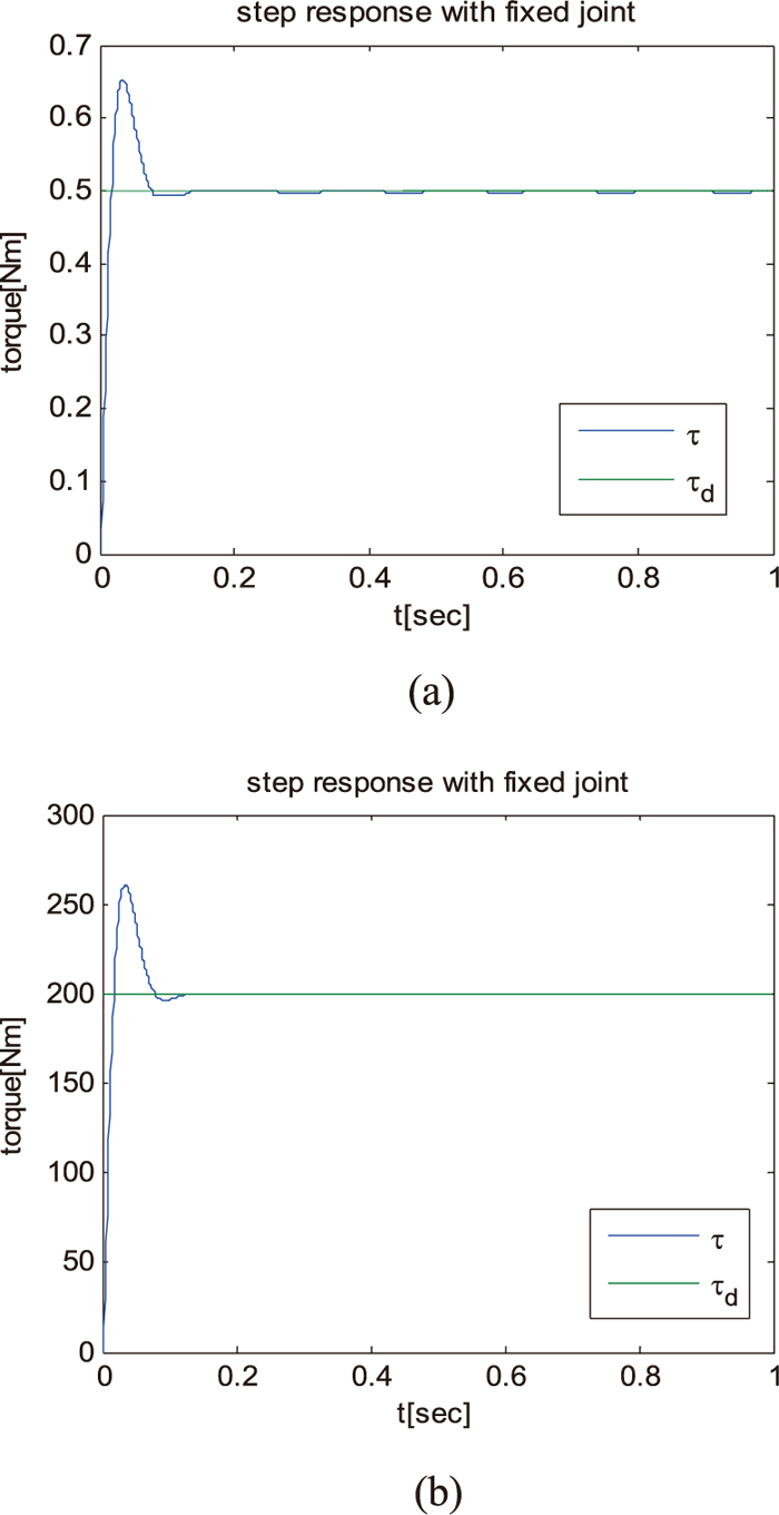
This section presents the simulation and experimental results of the shroud nozzle manipulator. The virtual 1-dof hydraulic rotary actuator was modeled and the torque output controller was simulated. Table 2 shows the actuator model parameters. The purpose of 1-dof actuator simulation and test is to verify the performance of the controller. Hydraulic actuator model was set in the simulator and various desired torque inputs were given. As a result of hydraulic rotary actuator model simulations with parameters, we confirmed that the torque outputs followed the desired inputs well at 0.5 and 200 Nm in Fig. 8, which represents the torque output controller generates appropriate torque value for the manipulator in various torque range.
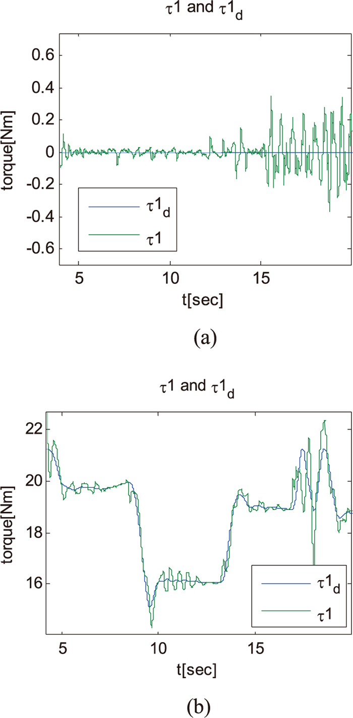
After the simulation of the actuator, the 1-dof hydraulic actuator’s test bed was fabricated to verify the simulation results. It includes the hydraulic rotary actuator, optical encoder, torque sensor, and external loads. Parameters in Table 2 were set at the test bed and experimental results were obtained in Fig. 9. The actuator was supposed to generates zero torque at any rotation angle in the first experiment. And the result shows that torque output followed the desired torque well in Fig. 9(a). The second experiment compensated 5 kg load and various torque command were generated. The torque output from the hydraulic rotary actuator also followed the desired torque command well in Fig. 9(b).
We verified that the torque output from the hydraulic actuator could be controlled by the suggested torque output controller with simulations and experiments. Suggested torque output controller was applied in the shroud nozzle manipulator.
4.2. Simulation and Experimental Results of the Manipulator
The simulator model for RoboticsLab was designed based on the actual CAD model of the shroud nozzle manipulator.14) Each joint includes joint torque sensor and the sixth joint, which is the passive joint, has just an encoder in the model. Six-axis force/torque sensor is installed on the ladle frame. Figure 10 illustrates the actual simulation model of the shroud nozzle manipulator.

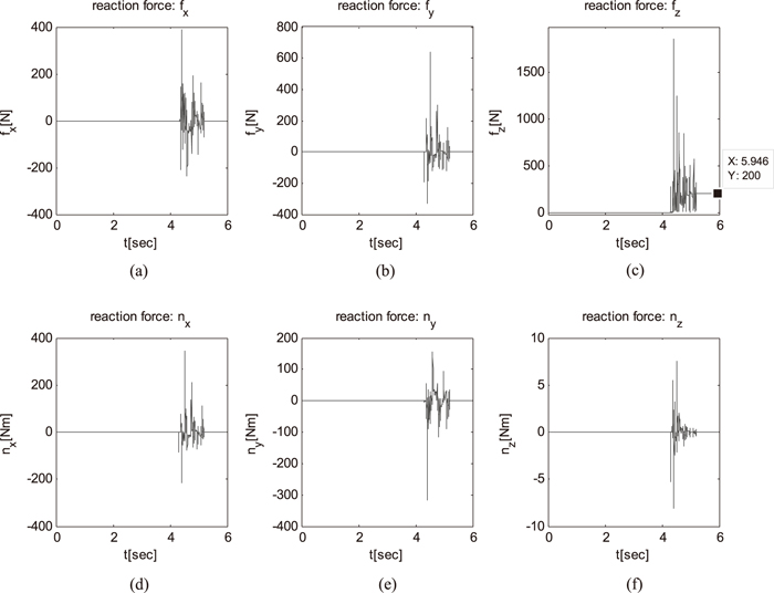
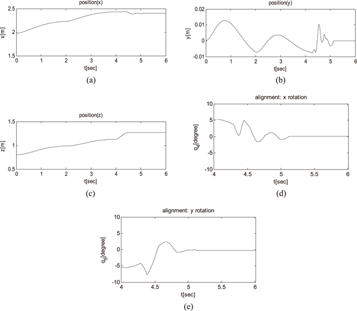
Figure 11 shows the simulation results of nozzle alignments. The target collector nozzle position was set at [2.4, 0.0, 1.1] in x, y, and z, respectively. The initial position error tends to diminish gradually and almost recovered after 5 seconds in Fig. 11. The shroud nozzle rotation angles around in x′ and y′ directions are disappeared after 5.15 seconds, which represents that the manipulator maintains the nozzle alignment. The simulation result explains that the precise position control is not required for connecting nozzles and the force control algorithm can compensate the initial position uncertainties. In other words, the manipulator does not need to generate the additional position trajectories in various situations. Figure 12 presents the force and torque simulation data obtained from the sensor on the ladle frame. The three graphs in the first row are force components and the three in the second row are torque components in x, y, and z, respectively. The shroud nozzle and collector nozzle begins contact after 4.5 seconds and the force ripples occur in every direction. Due to the initial position error, the force control algorithm takes some time to remove the position error. The force ripples disappeared after 5 seconds. Then force and torque equilibriums are achieved, where this means the nozzles are aligned correctly.
The simulation model of shroud nozzle manipulator demonstrates that the applied force integral control improves the nozzle alignment. The force integral control is robust to nozzle uncertainties and it does not need to create separate position trajectories.
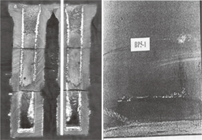
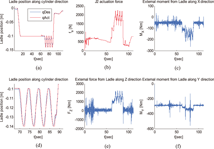
Figure 13 presents the experimental results of the shroud nozzle tightening force control. To simulate actual ladle motions, the collector nozzle frame generates 4 mm peak-to-peak sinusoidal motion with 0.2 Hz in z-direction after 70 seconds in Figs. 13(a) and 13(d). Figure 13(d) is the expanded view of graph (a) after the generation of sinusoidal motion. It demonstrates that the shroud nozzle position is controlled with respect to the ladle position. The vertical joint actuation force that is denoted as ② in Fig. 6 is supposed to actuate 1200 N to z-direction after 60 seconds with respect to the real-time collector nozzle position in Fig. 13(b). After the shroud nozzle has the physical contact with the collector nozzle, the force integral controller starts to find the proper position and alignment between nozzles, where it takes some time between 60–70 seconds. We could also verify that the manipulator generated around 1200 N in z continuously from the force sensor in the collector nozzle simulator in Fig. 13(e). The result presents that the end-effector follows the collector nozzle movement on ladle and maintains the tightening force at the same time. External moments in x and y-direction from the sensor are shown in Figs. 13(c) and 13(f), respectively. The target collector nozzle had initially a 5° angle offset. After the nozzle contact and vertical force generation, certain amount of external moments in x and y-direction on the nozzle occurred and it maintained constantly. This represents the shroud nozzle is aligned with the collector nozzle and both nozzles are sealed. Although the collector nozzle on the ladle is tilted, the end-effector with the shroud nozzle tends to find the proper alignment. In order to ensure the sealing between the collector nozzle and shroud nozzle, we put powder in the gap and blew the air inside the collector nozzle in Fig. 14. And we certified that the nozzle sealing caused no problems such as crevice and air leakage while both nozzles were tilted and fluctuated.
5. Conclusion
In this paper, the novel hydraulic shroud nozzle manipulator in continuous casting was developed and implemented. Since the existing manipulator in POSCO has the drawback of the nozzle misalignment, the new concept of shroud nozzle manipulator based on a robust force control was proposed. For instance, the initial nozzle position error and the external forces from the irregular flow of molten steel in the tundish cause the shroud nozzle misalignment, which leads to the air-inflow in the crevice between the shroud nozzle and the collector nozzle. The steel oxidation occurs by the contact with the air and it has a strong influence on the generation of defects in steel products. If the 5-DOF hydraulic shroud nozzle manipulator is applied in the shroud nozzle manipulation, however, it ensures the airtightness by maintaining the nozzle alignment and tightening force. Since the manipulator measures the external load on top of the nozzle in real-time by torque sensors, the shroud nozzle and collector nozzle can be connected in proper position without additional equipment for error measurement and control. Also, the position error caused by the external forces after the nozzle connection can be corrected by the applied robust force control.
The half-scaled hydraulic shroud nozzle manipulator platform verifies the validity of shroud manipulation tasks. Several simulations and experiment results demonstrate the capability of manipulator such as: The manipulator can continuously generate over 1200 N vertical force keeping the airtightness. The experimental results demonstrate that the manipulator followed the movement collector nozzle in the situation where the collector nozzle generates the 4 mm peak-to-peak oscillation with 0.2 Hz. Even though the collector nozzle is initially tiled, the shroud nozzle manipulator can align the nozzles by the suggested integral force control. In both cases, we put some powder in between the nozzles and blew the air inside the nozzle. The experiment showed that the manipulator can maintain the airtightness quite well. In the future, the proposed force controller needs to be tested against variable disturbance conditions.
References
- 1) B. Siciliano: Robot Force Control, Kluwer Academic Publishers, Norwell, MA, (1999).
- 2) J. Xiang, C. Zhong and W. Wei: IEEE Trans. Robot., 26 (2010), 660.
- 3) G. Hirzinger, J. Bals, M. Otter and J. Stelter: IEEE, Robot. Automat. Mag., 12 (2005), 16.
- 4) M. H. Raibert and J. J. Craig: J. Dyn. Syst-T ASME, 102 (1981), 126.
- 5) H. Yu, Y. J. Park, I. S. Choi, W. K. Chung and K. Kim: IEEE Conf. on Automation Science and Engineering, IEEE, Piscataway, NJ, (2012), 538.
- 6) B. Heinrichs, N. Sepehri and A. B. Thornton-Trump: IEEE Control Syst., 17 (1997), 46.
- 7) M. Kamezaki, H. Iwata and S. Shig1eki: SICE Annual Conf., SICE, Tokyo, (2010), 1255.
- 8) F. Bu and B. Yao: IEEE Int. Conf. on Robotics and Automation, IEEE, Piscataway, NJ, (2000), 4034.
- 9) S. R. Habibi, R. J. Richards and A. A. Goldenberg: American Control Conf., IEEE, Piscataway, NJ, (1994), 1003.
- 10) Y. Choi and W. K. Chung: Asian J. Control, 5 (2003), 206.
- 11) Y. Choi, W. K. Chung and Y. Youm: Proc. 2001 IEEE/RSJ Int. Conf. on Intelligent Robots and Systems, IEEE, Piscataway, NJ, (2001), 1656.
- 12) J. Park and W. K. Chung: IEEE T. Robot. Automat., 16 (2000), 847.
- 13) N. D. Manring: Hydraulic Control Systems, Wiley, Hoboken, NJ, (2005).
- 14) Simlab-Robotics Lab.: www.simlab.co.kr, (accessed 2015-04-01).