Regular Article
Enhancement of Rutile Formation by ZrO2 Addition in Ti-bearing Blast Furnace Slags
2015 Volume 55 Issue 7 Pages 1384-1389
Details
2015 Volume 55 Issue 7 Pages 1384-1389
Enhancement of rutile crystallization in Ti-bearing Blast Furnace (Ti-BF) Slag caused by various ZrO2 additions was clarified by Single Hot Thermocouple Technique (SHTT). Time-temperature-transformation (TTT) curves were obtained to analyze the variation trend of crystallization behavior. The results showed that the incubation time of primary crystal, i.e., rutile, at high temperature was first prolonged with increasing ZrO2 addition from 0 to 3 wt.%, and then visibly shortened with further addition of ZrO2 up to 5 wt.%. However, final amount of crystal precipitated was monotonously enhanced by the increasing ZrO2 addition. Meanwhile, Fourier Transform Infrared spectroscopy (FTIR) test was applied to investigate structure of the slag and it was found that degree of polymerization (DOP) for the slag was enhanced and the structural group related to Zr–O–Zr group became more pronounced with increasing ZrO2 concentration, which agreed well with the variation trend of the crystallization behaviors of slags. These results have highlighted that addition of ZrO2 could enhance rutile crystallization, which is of great importance for potentially extracting Ti element from the slag.
China has approximately 50% of the total titanium reserve in the world. However, about 98% of titanium resource is in the form of vanadium-titanium magnetite ores, which is generally treated with blast furnace ironmaking process (BF process) to extract valuable elements (e.g. V, Fe) from iron ore concentrate. In this process, Ti element is concentrated into the molten slag and discharged into the slag pit, forming the typical Ti bearing blast furnace slag waste (Ti-BF slag) containing 22–25 wt.% TiO2.1,2) The deposition of such waste not only poses hazardous effects on environment but also is a great loss of titanium resource. Therefore, it is necessary to develop a utilization method to treat these Ti-BF slags and extract Ti element efficiently. During past decades, many methods have been developed to extract Ti from Ti-BF slags, such as acid leaching,3,4) alkaline molten salt method,5,6) carbide-chloride method7,8) and selective crystallization and phase separation (SCPS) method.9,10) Currently, SCPS method has been thought as one of the most promising methods, which can enrich Ti element into a selected crystalline phase, which makes the extraction of titanium become feasible. Rutile is regarded as an appropriate enriched phase for SCPS method because of its rod-shape structure, high density and high content of Ti.11,12) However, the rate of rutile formation is still not satisfactory, it is therefore necessary to further explore methods to promote the rutile formation.
ZrO2 is widely used as an effective nucleation agent in mold slags because of its high stability and low solubility.13,14,15,16) Beall et al.17) found that the nucleation reagents played various roles during crystallization from liquid phases, i.e. an increasing driving force and a reduction of the interfacial energy between the crystal and the liquid. Most importantly, the nucleation reagents may precipitate or combine with some other elements to form some solid phases and thus initiating heterogeneous nucleation of the major crystalline phase.17) Actually, the addition of ZrO2 has been reported to successfully facilitate CaO–MgO–Al2O3–SiO2 glass crystallization.18,19) Some other researchers also discovered that ZrO2 particle only has a limited solubility in molten slag and can induce heterogeneous nucleation sites, which results in the enhancement of the crystallization of the slag.13,14,15,16,20,21) Furthermore, ZrO2 is also regarded as a network former reagent and the addition of ZrO2 in the slag is also found to increase both the viscosity and crystallization temperature of the slag.15,22) Overall, crystallization of the ZrO2-containing slag is determined by the combination of the viscosity of the slag and heterogeneous nucleation induced by ZrO2,13) which are closely related to structure of the slag. However, investigation on the effect of ZrO2 by many researchers were mainly focused on how it acted as nucleation agent while limited researches were conducted to see how it could modify structure of the slag and thus affecting crystallization behavior of the slag. The present study was therefore motivated.
In this paper, a systematical research was conducted to investigate the effect of ZrO2 addition on the crystallization behavior and mechanism of Ti-BF slags. Besides, Fourier Transform Infrared spectroscopy (FTIR) was applied to study the structural change caused by ZrO2 addition and to clarify the relationship with crystallization. Overall, the present research will not only provide us some deep insights into the role of ZrO2 in the crystallization of the Ti-bearing slag, thus extracting Ti element more efficiently, but also give us substantial evidence for the application of ZrO2 in the other slag system such as mold slag.
Table 1 shows the chemical composition of the slag used in this study. The samples were synthesized with analytical grade CaO, MgO, Al2O3, SiO2, TiO2 and ZrO2. The mixtures were melted in a Pt crucible at 1773 K under the purified Ar atmosphere for 1 hour to homogenize the chemical composition. Then, the slag melt was quenched by the cool water. Subsequently, the slag was ground to below 200 meshes for the following Single Hot Thermocouple Technique (SHTT) experiment, X-ray fluorescence spectroscopy (XRF), X-ray diffraction (XRD) and FTIR measurements. Table 1 also lists the chemical composition of the samples analyzed by XRF.
| Sample | CaO | SiO2 | Al2O3 | MgO | TiO2 | ZrO2 | basicity | Sum | |
|---|---|---|---|---|---|---|---|---|---|
| A1 | Designed | 19.00 | 38.00 | 12.10 | 6.90 | 24.00 | 0.00 | 0.50 | 100 |
| Analyzed | 19.13 | 34.61 | 13.88 | 7.68 | 24.70 | 0.00 | 0.55 | 100 | |
| A2 | Designed | 18.67 | 37.33 | 12.10 | 6.90 | 24.00 | 1.00 | 0.50 | 100 |
| Analyzed | 19.10 | 33.22 | 13.98 | 7.70 | 25.07 | 0.93 | 0.57 | 100 | |
| A3 | Designed | 18.00 | 36.00 | 12.10 | 6.90 | 24.00 | 3.00 | 0.50 | 100 |
| Analyzed | 17.97 | 33.69 | 13.84 | 7.62 | 24.26 | 2.62 | 0.53 | 100 | |
| A4 | Designed | 17.33 | 34.67 | 12.10 | 6.90 | 24.00 | 5.00 | 0.50 | 100 |
| Analyzed | 17.58 | 31.68 | 13.53 | 7.32 | 24.91 | 4.98 | 0.55 | 100 | |
Isothermal experiments using Single Hot Thermocouple Technique (SHTT) were conducted to construct TTT diagrams. The principles of SHTT have been described in details in some previous papers23,24) and briefly outlined as follows. A Pt-Rh thermocouple (B Type) was used to heat or cool the sample and measure the temperature simultaneously. The heating and cooling processes were controlled by a computer program. Pictures of the melt were recorded by a microscope equipped with a video camera, which were then sent to the computer and analyzed to study the crystallization behavior. In each experiment, about 10 mg samples were placed on the tip of the thermocouple. Then, the sample was heated to 1500°C and held for 120 s to eliminate the bubbles in the molten slag and homogenize its chemical composition. After that, the molten slag was rapidly cooled down (50°C/s) to the designed temperature and held for 300 to 1200 s for isothermal experiments. The time for the onset of crystallization was documented by analyzing the recorded images and the corresponding TTT diagram was plotted as a result.
2.3. Sample AnalysisFTIR was used to analyze the slag structure. The sample was fully mixed, pelleted with KBr powders and then tested in the range from 4000 to 400 cm–1. The crystalline mineral phase of the samples were analyzed by XRD in the 2θ scanning range of 10–80° with a scanning speed of 4°/min. The samples were obtained by putting about 5 g amorphous slag in a Pt crucible, melted at 1500°C and then followed by a rapid cooling to the preset temperature holding for 2 h. After that, it was rapidly quenched in the cool water and finally ground to below 200 meshes for the analysis of XRD. SEM equipped with energy-dispersive X-ray spectroscopy (EDX) was applied to analyze the morphology and elemental compositions of the samples obtained from SHTT experiments. The samples were then embedded in the electric resin epoxy, polished and finally coated with a thin layer of gold film for the SEM test.
Figure 1 shows the TTT diagrams of the samples determined by SHTT methods. The points at the right end represent the respective crystallization temperatures. As can be seen, the crystallization temperature increases successively with increasing ZrO2 content. This result agrees with the previous researches, which pointed out that addition of ZrO2 enhanced the crystallization temperature of the slag.16,22) The reason to the increasing crystallization temperature may arise from the fact that ZrO2 only has limited solubility in the slag and induces nucleation sites when it precipitates from the slag even at relatively high temperatures. However, it can also be observed that the incubation time of crystal formation first increases with increasing ZrO2 content from 0 to 3 wt.%, then abruptly gets shorter with 5 wt.% ZrO2 addition in the slag. The reason to the prolonged incubation time may be the increased slag viscosity caused by ZrO2 addition, as with the work by Tregubenko,37) which proved that viscosity of CaO–Al2O3–ZrO2 slag increases successively from about ~2 Pa.s to ~14 Pa.s at about 1775°C with increasing ZrO2 content from 10 wt.% to 40 wt.%. And this trend has also been used to illustrate the crystallization trend in other slags13). It is therefore concluded that with increasing ZrO2 up to 3 wt.%, slag viscosity increases and thus prohibits the mass transfer of ion groups for crystal formation. The nucleation ability abruptly increases with further increasing ZrO2 content up to 5 wt.%. Considering the fact that crystallization is determined by the competitive balance between nucleation and the growth of crystals, it is therefore concluded that incubation time is the longest for 3 wt.% ZrO2, and then gets shorter with 5 wt.% ZrO2 in the slag.

TTT diagrams of four samples with varying ZrO2 content.
The effect of ZrO2 addition on the morphology of crystal was investigated by SHTT images, as shown in Fig. 2. It can be found that the initial crystallization at 120 s is inhibited with increasing ZrO2 addition up to 3 wt.%, as shown in Figs. 2(a1), 2(b1) and 2(c1). However, further addition of ZrO2 up to 5 wt.% significantly prompts crystal formation as shown in Fig. 2(d1). These results are similar to the change of the incubation time and agree well with the TTT curves in Fig. 1. However, when crystallization time is increased to 600 s, it can clearly be observed from Fig. 2 that the crystallization rate, which is defined as the ratio of crystal area to the area of the thermocouple tip, increases continually with increasing ZrO2 addition in the slag. For sample A1, only tiny amount of crystal is formed; while for sample A4, the formed crystal already covers the whole thermocouple tip at 600 s. It is therefore concluded that an increasing ZrO2 concentration up to 3 wt.% first suppresses crystallization in the short time, while leads to great enhancement of final crystal amount. When ZrO2 reaches 5 wt.%, it could not only decrease the incubation time for crystallization, but also prompts the final amount of crystal precipitated from the slag.

SHTT images of four samples holding at 1240°C for 120 s and 600 s.
In addition, it can also be clearly observed that crystal morphology drastically changes with varying ZrO2 addition. Specifically, when the temperature is above 1100°C, only rod-shape crystal precipitates for samples A1 and A2, while the crystals with blocky shape was observed for samples A3 and A4. Considering the increasing crystallization temperature from 1260°C for sample A1 to 1300°C for sample A4 as confirmed by TTT curves, it can be concluded that the temperature range over which rod shape crystal could form increases with increasing ZrO2 additions. When the samples are held at temperatures below 1100°C, cloud shape crystals can be formed for all the samples.
To identify micro-structure of the precipitated crystal, SEM was applied and the results of samples A1 and A4 crystallized at 1240°C are showed in Fig. 3. It shows the crystal morphology for sample A1 and the rod-shape crystal was observed, which is in agreement with the SHTT images. In terms of the microstructure of the blocky crystal, as shown in Fig. 2 for sample A4, it is much different. Many small irregular oval-like crystals were observed, which are the cross section of these crystals. Meanwhile, several rod-shape crystals are also observed from longitudinal section of the crystal together with some other oval-like rutile. These results help to explain that the oval-like crystals are actually rod-shape if seen from the longitudinal section and further prove that the blocky crystal is actually comprised of many small rod-shape crystals.

SEM images of samples. (a) A1 at 1240°C kept for 600 s (b) A4 at 1240°C kept for 600 s.
The EDX spectra of the samples A1 and A4 are also labelled in Fig. 3, which proves that the crystals are rutile. While in sample A4, rutile is observed to precipitate together with Zr element, which agrees well with Beall’s study that nucleation reagents can also precipitated together with other elements and then induce nucleation sites.17)
Moreover, the mean diameter of rutile crystals was also obtained by Image Tools 3.0 (The university of Texas Health Science Center at San Antonio, Texas, USA). For sample A1, the mean diameter is determined to be 1.88 μm. While for crystals from sample A4, the mean diameter for crystals was measured to be 1.39 μm, smaller than the rutile crystal from sample A1. With increasing ZrO2, the number of rod shape crystal increases and they are dispersed in the slag as proved by the analysis of SEM. Although the diameter for single crystal is relatively smaller in Sample A4, the overall crystal amount is much greater compared with crystals formed in Sample A1, which is in agreement with the SHTT images in Fig. 2. This might arise from the fact that more nucleation sites were precipitated in the slag melt with ZrO2 addition. However, an increasing nucleation sites also result in less space for each crystal to grow and leads to a decreasing diameter of the single crystal.
To verify that ZrO2 could really prompt the heterogeneous crystallization and determine the effect of the temperature on the crystallization of the slag, the crystalline phases of the quenched samples were analyzed by XRD. Figure 4(a) shows the XRD patterns for four samples quenched at 1240°C while Fig. 4(b) gives XRD patterns of sample A4 quenched at 1300°C, 1240°C, 1080°C and 1020°C, respectively. From Fig. 4(a), it could be observed that the XRD patterns gradually changed with the increasing concentration of ZrO2. The peaks were identified and rutile was observed to be the dominant crystal phase for all four samples quenched at 1240°C. New crystal phases were also observed, such as ZrO2 in sample A2 and A3 and Ti2ZrO6 in sample A4, which can be regarded as the combination of ZrO2 and TiO2. These new formed phases may be explained that they can act as nucleation reagents and prompt rutile crystallization. These results indicates that ZrO2 can precipitate from the slag and are sometimes precipitated together with some other elements and thus initiating heterogeneous nucleation of the major crystalline phase and providing nucleation site for crystal formation, which is in agreement with a previous study.17) It is interesting to note that the relative intensity of XRD pattern for rutile increases with increasing ZrO2 addition, suggesting that an increasing amount of rutile precipitated from the slag, which agrees with the results of SHTT as shown in Fig. 2. The influence of quenched temperature on the crystal formation was also investigated, and the results are shown in Fig. 4(b). It is obviously observed that the rutile is the dominant crystal phase in the whole temperature range and the relative intensity increases with decreasing temperature. However, with decreasing temperature, several crystal phases are co-present in the slag. Apart from rutile, Ti2ZrO6 is found to present at 1240°C. When the temperature was 1080°C or below, CaTiSiO5 and CaAl2Si2O8 were precipitated from the slag. Finally, it can be concluded that the major crystalline phase is determined to be rutile and the multiple phases over the low temperature range show that crystallization process becomes complicated.

XRD results of samples. (a) four samples holding at 1240°C (b) Sample A4 holding at varying temperature.
According to the experimental results, it is recommended that 5 wt.% of ZrO2 might be essential in modifying the Ti-BF slag. To derive Ti enriched crystalline phase, the modified liquid slag is first rapidly cooled and then held at the well-controlled holding temperature and time to ensure the full growth of crystals. Then, the slag is rapidly quenched to room temperature. Finally, some separation methods, such as froth flotation and gravity separation could be used to obtain the Ti enriched crystalline phase.
3.3. FTIR AnalysisConsidering the introduction of additive would significantly result in the change of the structure of the melt slag, FT-IR spectroscopy was then applied to investigate effect of ZrO2 on the structure of the slag. As shown in Fig. 5, the FTIR spectrum consists of a strong broad band in the wavenumber range of about 1200 to 800 cm–1, a medium intense band between about 600 and 480 cm–1 and a weak band between 790 and 620 cm–1, which are assigned to [SiO4]– tetrahedra, Si–O–Si bending vibration and symmetric stretching vibration of [AlO4]- tetrahedral, respectively,25,26,27,28,29,30,31,32) and the adsorption bands of different structural units are showed in Table 2. The strong wide band generally consists of four peaks at about 860, 920, 960 and 1080 cm–1, corresponding to the stretching vibration of [SiO4]- tetrahedra with various NBO/Si(4,3,2,1),25,26,27,28,29,30) namely Q0, Q1, Q2 and Q3. There are several typical characteristics appeared in the present FT-IR results. First, the characteristic stretching vibration band relates to the large silicate network structures become more pronounced and the depth of the convoluted band becomes deeper with increasing ZrO2 addition. This increase in the depth of the transmission trough indicates the increased degree of polymerization (DOP) of the slag structure as suggested in some previously published literatures.33,34) In addition, the lower limit of the band for [SiO4]- tetrahedra shift successively to a higher wavenumber region, i.e. from 795 cm–1 for sample A1 to 812 cm–1 for sample A4, indicating that more [SiO4]- tetrahedra with lower value of (NBO/Si) ratio (such one and two) appears and the DOP of the slag was therefore increased. Therefore, the FTIR tests do seem to suggest that ZrO2 could modify the structure of the slag by increasing its DOP. The increased DOP generally means an increase of the slag viscosity and thus inhibits initial crystallization of the slag. The results explained the increasing incubation time of the crystal formation as shown in TTT curves in Fig. 1 and the inhibited initial crystallization in Fig. 2.
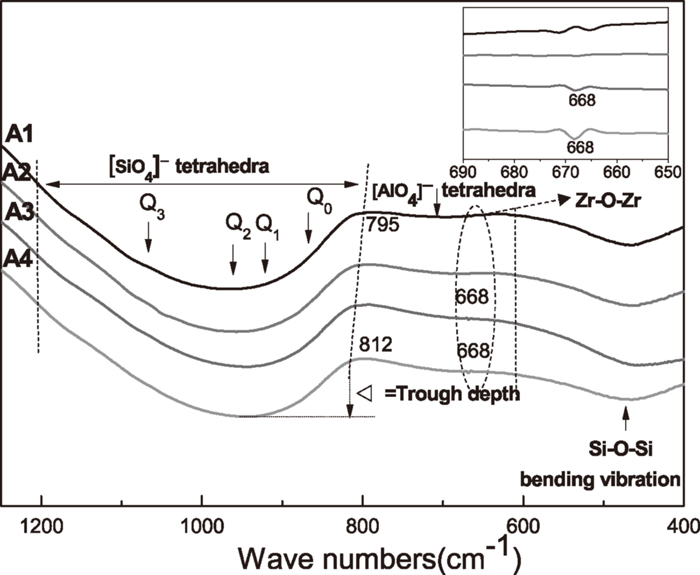
FT-IR transmittance of the samples quenched by cool water as a function of wave numbers.
| Frequencies of FTIR adsorption bands (cm–1) | Recommended units |
|---|---|
| –860 | Q0 of monomer units |
| –920 | Q1 of dimer units |
| –960 | Q2 of chain units |
| –1080 | Q3 of sheet units |
| 800–610 | [AlO4]- tetrahedra |
| 610–400 | Si–O rocking vibration band |
| 668 | Zr–O–Zr band |
Furthermore, with the introduction of ZrO2, a new band assigned to Zr–O–Zr bond appears at 668 cm–1,35) and the relative intensity also increases with increasing ZrO2 content. It can be therefore concluded that the addition of ZrO2 is closely correlated with the enhancement of the polymerization of the melts. This is in agreement with Riboud et al.’s work that ZrO2 has the same function as SiO2 in the silicate slags.36) It is then speculated that ZrO2 is a network-forming oxide and Zr4+ would exist in the form of [ZrO4]- tetrahedra incorporated into the [AlO4]-tetrahedral units. Therefore, viscosity of slag melt increases with increasing ZrO2 addition15,22) and hinders rutile formation. Besides, the appearance of [ZrO4]- tetrahedra also indicates that it can inhibit the chemical reaction between CaO and TiO2, thus promoting crystal precipitation in the form of rutile, instead of CaTiO3. Since ZrO2 only has a limited solubility in the slag, the presence of Zr–O–Zr bonds provides evidence for the precipitation of the ZrO2 and Ti2ZrO6 particles when it cools down, thus enhance the final amount of rutile formed and it is in consistent with the SHTT images shown in Fig. 3 and the increasing XRD intensity for rutile shown in Fig. 4.
This study explored the role of ZrO2 on the crystallization behavior of slags and identified the enhancement of rutile formation in the Ti-bearing slags. SHTT experiments proved that crystallization of the slag was prompted and the crystallization temperature increased successively with increasing ZrO2 content. The FTIR results showed that DOP of the slag was improved with increasing ZrO2 concentration, which could cause an increasing viscosity and therefore a longer incubation time of rutile in the ZrO2 range of 0–3 wt.%; meanwhile, SEM and XRD tests proved that ZrO2 particles could act as the heterogeneous nucleation reagent, facilitating the crystallization of the slag and thus leading to a decreased incubation time for slag with 5 wt.% ZrO2. Furthermore, the increasing ZrO2 resulted in the enhancement of final rutile crystallization in all samples. Most importantly, this study could provide fundamental insights into the role of ZrO2 during the crystallization of the slag and will be of some help to extract Ti element from the slag.
This study was sponsored by the National Natural Science Foundation of China (51472007 and 51074009); The National High Technology Research and Development Program of China (863 Program, 2012AA06A114); The China National Key Technology R&D Program (2013BAC14B07) was also acknowledged.