Regular Article
Using Electromagnetic Levitation for Continuous Casting of Thin Aluminium Alloys Strip
2015 Volume 55 Issue 8 Pages 1669-1676
Details
2015 Volume 55 Issue 8 Pages 1669-1676
The paper presents a method for computing the parameters of an electromagnetic mould for a horizontal continuous casting of thin aluminium alloys strip. The method is based on the calculation of the distribution of the magnetic field, which is based on the interaction between the inductor and the surface of the shaped molten metal. The interaction of fields of the inductor and its mirror image in the molten metal moves the centres of the electrical current flow closer together and increases the current density at the inductor’s face adjacent to the liquid metal. The operating frequency of alternating current flowing through the inductor, which depends on the density, the surface tension, and specific electrical conductivity of the liquid metal, and the pool thickness, is determined. The mould was designed for the electromagnetic levitation a free surface of 150 × 20 mm strip from AlSi8.5Cu and AlSn20 alloys. It consists of a system of special inductors which are of the different configurations for shaping the upper and lower surfaces. At the inductor’s width of 28 mm, the uniform magnetic field ensuring the steady air gap between the inductor and the liquid metal can be expected over the length of 24 mm.
An important milestone was reached in the development of continuous casting technologies for aluminium alloys, with the substitution of the mechanical contact of the solidifying molten metal with the mould’s walls for shaping a free surface, with the use of an electromagnetic force instead. The function of confining and shaping was taken over by a special coil - inductor known as an electromagnetic mould (EMM).1) The conventional vertical EMM has been successfully used on a slab section up to 1 m2. Today, when the trend is towards reducing the slab section and producing a near-net-shaped product, horizontal electromagnetic casting can offer a solution to this problem.2) Many studies have been conducted on the vertical EMM, focussing on free surface shaping,3,4,5,6) but only a small number of papers have been published on computing the parameters of horizontal EMM and determining their boundary values.7) EMM development was initiated at authors` workplace with the aim of replacing the technology of continuous casting of a 150 × 30 mm strip in a horizontal graphite mould from which the desired semi-product with a section of 150 × 20 mm, and without any surface defects was achieved by milling 5 mm from each surface layer.
The development of an electromagnetic mould arranged horizontally began when the authors discovered experimentally that as the molten metal approaches the mould, the value of the electromagnetic repelling force increases simultaneously. When the air gap is reduced from 5 to 0 mm, a steep increase in the repelling force ensures a steady positioning of the molten metal’s surface to the inductor. In the early stages of investigation, the calculation of the parameters for the horizontal EMM (HEMM) started with the experimentally determined dependence of the air gap a on the magnetic field intensity H. This was then transformed into a mathematical form using regression analysis.8) In the next stage,9) increasing the pressure generated by the magnetic field when the air gap is reduced was explained as the result of interactions between the electrical current of the inductor and the conductive liquid metal. On this basis, the relations were formulated to compute the dependence of a-H in the working space of a real inductor using the finite element method.10)
The method of HEMM design presented is based on the calculation of the magnetic field distribution, which is based on the interaction between the inductor and the surface of the shaped molten metal. The condition of equilibrium between gravitational force and electromagnetic force in the HEMM can be defined according to the equation:3,11)
| (1) |
The analysis of the specific situation when the molten metal is brought closer to the inductor’s face will be conducted with the inductor which has a cross-section with an external central peak as shown in Fig. 1. This is in contrast to the simple conductor of a 10 × 40 mm rectangular section used in the HEMM prototype, shown in Fig. 2.
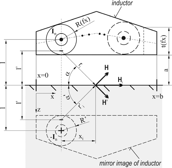
Inductor with a central peak.
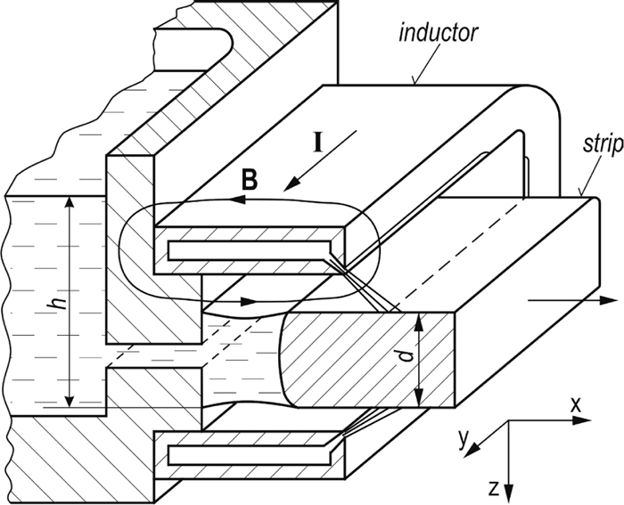
Horizontal EMM with the inductor of the rectangular cross-section (h – height of the liquid metal; d – thickness of a strip).
The interaction of fields of the inductor and its mirror image moves the centres of the electrical current flow closer together and increases the current density at the inductor’s face adjacent to the liquid metal. In such a case, the conductor with radius R through which the current I passes, at a distance l from the electric conductive face of the molten metal, will generate a magnetic field equal to the one generated by a conductor of zero thickness having the values of the current I the same, but at the distance of l’ from the surface different, i.e. where l2 = l′2 + R2.10,12,13) Then the magnetic field intensity Hi on the molten metal surface will be the vector sum of both components from the conductor itself H and from its mirroring image H’. If the inductor is at a distance a from the liquid metal, when l = a + R, the addition of intensity Hi from the selected element at a distance xi from the perpendicular to the surface will be:
| (2) |
| (3) |
| (4) |
| (5) |
After entering the liquid metal, the alternating magnetic field induces an electrical current in it, which generates its own magnetic field, but the opposite one. As a result, the field decays exponentially when penetrating, and both interacting fields produce the force acting in the liquid metal in the direction from the inductor. At any depth z, in every element of the volume having an area of 1 m × 1 m and the depth dz the increase of force df arises, and is numerically equal to the increase in the pressure dp (N.m−2). At any depth z under the surface we calculate the total value of pressure pm using the integration of all the additions in an interval from the surface, where z = 0, to the depth z, when we get:4,14)
| (6) |
| (7) |
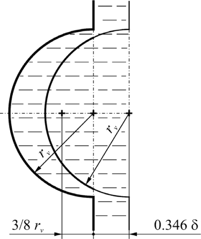
A jut on a free surface.
At the point of the jut creation, the metallostatic pressure is balanced by the pressure developed by the magnetic field and the centres of its action lay at a depth of 0.3466δ under the surface in the direction of the propagating field. The array of these centres of action has the same hemisphere shape with the radius rv, equal to that of the jut, but its centre is shifted under the plane of the liquid metal at a depth of 0.3466δ. At the axial cross-section of the jut, the surface of the spherical cap above the liquid metal plane is shaped like an arc of a circle, at the centre of which the total pressure developed by the field is acting. The centre of an arc of a circle according to analytic geometry lies on its axis at a distance of rvt/l from the centre where t is the chord length and l is the length of this arc.
Gravitational force acts on the hemisphere’s centre which is located at a distance greater than 3/8 rv from the plane of the molten metal pool. In order to prevent the hemisphere from sliding in the direction of gravity, the centre of the electromagnetic force acting on it has to be located at a distance greater than 3/8 rv from the molten metal plane. In a threshold situation, both centres will be identical (3/8rv + 0.3466δ = rvt/l) which is fulfilled when rv ≈ 0.816δ. Inside the jut the metallostatic pressure of the liquid metal column of the height h = 2rv, which is in equilibrium with the surface tension force, is experienced. If we substitute into Eq. (7) for h = 2rv and the dependence rv ≈ 0.816δ, under these conditions the centres of electromagnetic and gravitational forces have a congruent location, then the expression relating to the minimum working frequency f, after transforming takes the form:
| (8) |
Experiments carried out with liquid Al alloys or PbSn in the inductor with a working frequency of 10 kHz have shown that small volumes of the liquid metal placed in a ceramic crucible in the inductor’s working space had a tendency to spontaneously move from side to side and their free surface to ripple. This was irrespective of whether the crucible was orientated vertically or horizontally. When increasing the pool dimension, adding more than three times the magnetic field skin depth of metal in the direction of the magnetic field penetration, a marked decline in the oscillations in the liquid metal surface could be observed. After substituting the empirical condition d = 3δ for the skin depth expression, we can determine the lowest applicable working frequency fd limited by the pool’s thickness d, when fd = 2.277.106/σd2. The working frequency of the EMM has to be higher than or equal to the highest one of the values limited by the surface tension, the minimum frequency fmin, and the dimensions of the liquid metal pool fd. To introduce the dependence of the minimum pool dimension dmin on the working frequency into the conditions defined by Eq. (5), we substitute h = 3δ for the column height. Under this condition, the value of the power density Nd will be constant, and proportional to the density and the specific electric resistance of liquid metal:
| (9) |
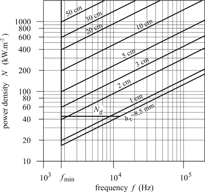
Dependence of power per area unit on a frequency at the different heights of AlSi8.5Cu alloy.
In a co-ordinate system with a logarithmical scale, where the values of power density N are on the vertical axis and frequency values f are on the horizontal one, the conditions of the equilibrium N-h are shown as a system of lines for the separate values of the height of molten metal column. The boundary conditions at values rτ = hτ = hmin and fmin are lines which limit the interval of the parameter values under which the conditions of reliable EMM performance are met. The line of values Nd, where the condition h = 3δ holds, allows us to read the minimum thickness of the pool dmin for a given frequency. For the given thickness d, the line of value h=d intersects the line Nd at the frequency fd which is the lowest value which can still be used to cast the strip of thickness d. Bellow the line Nd, at the height interval rτ ≤ h ≤ 3δ, there are a range of parameters under which the performance of the vertical EMM is maintained.
At the development of horizontal electromagnetic mould authors have attached much significance to experiments the aim of which was to find out a dependence of magnetic field intensity H on the value of a gap between the molten metal surface and the inductor in inductor’s working space.10) The experimental measurements were carried out in the inductor of the prototype unit which is shown in Fig. 2. The simple rectangle cross-section of the 10 × 40 mm inductor has provided a good approach to the working space when taking a measurement. In Fig. 5, there are presented the experimental found out courses of magnetic field intensity H depending on gap’s size and inductor’s shape when alternating current of frequency of 10 kHz and intensity of 3200 A (r.m.s value of 2260 A) was imposed.

Measured dependences of H – a on the surface of the molten metal levitating above the inductor at a current of a peak value of 3200 A (r.m.s value of 2260 A).
Laboratory HEMM enabled to take measurements at gap values ranging from 1 to 10 mm and the molten metal of the height up to 70 mm which was kept in a corundum crucible or free levitated. Part of experimental measurements was performed under model conditions in the vertically oriented working space when the molten metal pool was supported from below by a fireclay board. The solid aluminium alloy was inserted into the inductor, and after its meltdown the desired height of the molten metal was reached by adding an extra metal. Experimentally attained sets of H-a values have provided data for next analytic works and development of expression which enable to determine the value of Hx at any point of the molten metal surface having x-coordinate:
| (10) |
Based on experiments which were aimed at determining the lower power limit of the EMM and HEMM parameters, the hypothesis was developed that the fundamental limiting factor is the internal motion in the liquid metal produced by the non-potential action of the electromagnetic forces which would inevitably impact on the primary structure formation.18) To verify this assumption an experiment was carried out where in the vertical oriented inductor a cone of Al alloy was melted down on a thermo-insulating insert, the centre of which was cooled by immersing a water-cooled copper pipe of ϕ10 mm in the shape of an arch with a radius of 20 mm. After stabilizing the heat balance, most of the liquid metal was solidified and after switching off the device the block of solidified metal containing the cooling pipe was taken out of the inductor.
As shown in Fig. 6, at the edge of the sample adjacent to the inductor where the cooling rate was the lowest, and however, where the level of the effect from the alternating magnetic field and the electric current flow was the highest, the gradual transition of an eutectic morphology from finely dispersed at the edge to the typical dendritic structure on the length corresponding to the skin depth δ can be observed (Fig. 6(a)). The structure consists of fine dendrites of the primary solid solution with no clear orientation. Under the surface at a depth greater than δ ≈ 3.2 mm, the microstructure is almost the same as was found over most of the section in central zones of the sample. It consists of the primary solid solution and eutectic (α + Si) of the transition morphology type (Fig. 6(b)). The fact that more marked changes in the morphology occur only at a distance about the skin depth δ from the surface, can most likely attributed to the internal motion in the subsurface layer. Metallographical tests provide data to explain the causes of the morphology changes, and allow some prediction about the structure characteristics of the strip material cast in the HEMM.
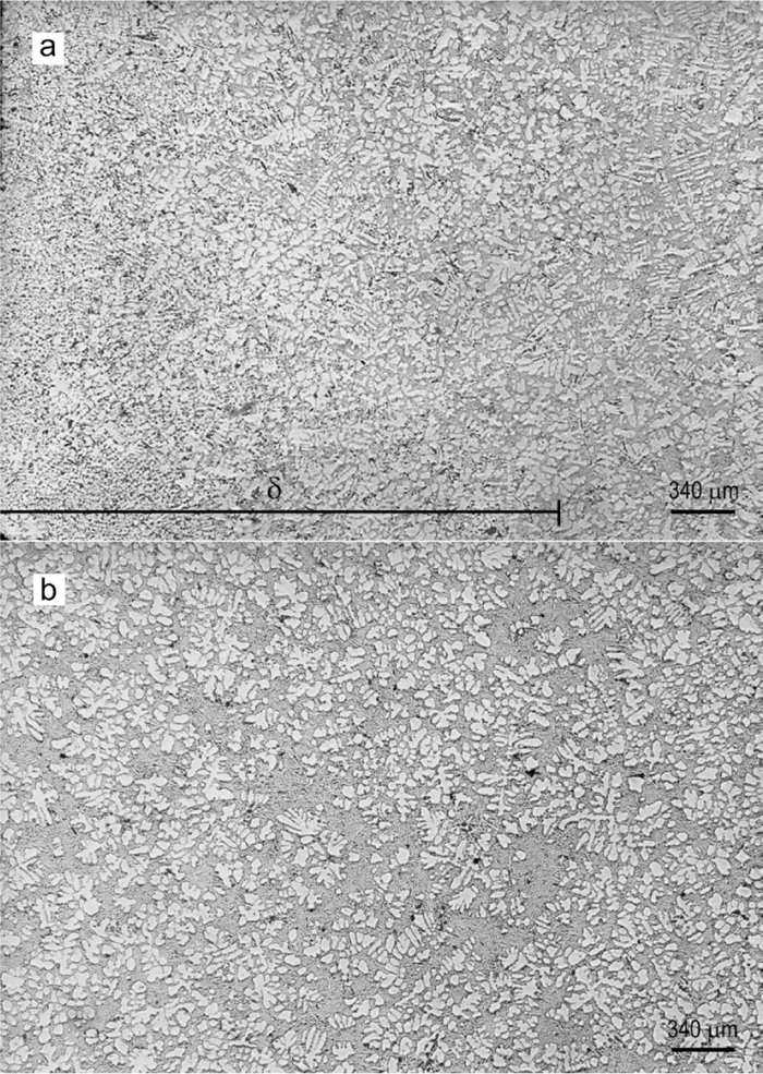
Microstructure of the AlSi8.5Cu alloy: (a) from the sample edge to a distance of 1 δ; (b) at a distance of more than 1 δ.
Experiments9,10) conducted with the laboratory HEMM comprising one coil inductor having a conductor section of 10 × 40 mm for casting the profile of 150 × 20 mm, as illustrated in Fig. 2, proved the feasibility of electromagnetic shaping the strip in the horizontal arrangement. The unit was powered by a generator intended for ultrasonic application with a power output of 10 kW and operating frequency of 10 kHz. The inductor used was characterized by a high drop in the magnetic field intensity in the direction away from central zone, and levitation of the liquid metal could be produced over a length of ± 5 mm from the centre. At a larger distance the free surface of the liquid metal rippled uncontrollably.9,10) The experiments carried out have shown that this length of active zone, provided by such an inductor, while being adequate for levitation generated by the uniform alternating magnetic field, was at the limit of application. It was evident that to extend the zone of active shaping in the direction of the exiting strip would be most easily achieved by enlarging the inductor, but such a solution would entail an increase in energy consumption. Therefore, the research was focused on the problem of how to extend the levitation zone without enlarging the inductor. Changing the wire cross-section from a simple rectangular shape (Fig. 2) to a more complex shape (Fig. 1) was proved to be the solution.
The next step in the development of a HEMM prototype highlighted the group of problems which have to be worked out before the prototype can be tried under production conditions. These include determining the boundary parameters of the shaping process, the air gap size, and at both horizontal surfaces the edge radiuses of the shaped strip, and with the respect to the different conditions of shaping of the upper and lower surfaces of strip, devising a suitable engineering design of the inductor. Two designs of inductors capable of shaping the lower and upper surfaces, together with the distribution of the magnetic field, are presented in Fig. 7.
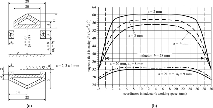
Arrangement of inductors for shaping of both surfaces (a), and the distribution of the magnetic field at an electric current of a peak value of 2520 A (b).
Research undertaken with the laboratory HEMM with the inductor of a 10 × 40 mm section has shown the solidification zone has to be located in the distance of ± 10 mm from the middle where the value of the air gap is changed about 1 mm. The difference in air gap values from 20 to 21 mm above the upper surface were chosen to ascertain over what length of the inductor in the direction of exiting it is possible to keep this range of air gaps. From the distribution of the magnetic field intensity (Fig. 7(b)) it follows that at the nominal value of magnetic field intensity of 32 kA.m−1 the arrangement with auxiliary inductors placed 6 mm below the main inductor ensures that the air gap will be ranged from 20 to 21 mm (a1 = 8 and 9 mm) between coordinates of 2 and 26 mm, which means over the length up to 24 mm. Over this interval, the internal movements of molten metal will be only negligible. Positioning an auxiliary inductor at the outlet makes it possible to locate a barrier directly at the edge of the working space of the inductor to prevent water entering into the solidification zone. It can be a curtain, baffle or roller, made from silicon rubber. The design can be seen as successfully developed and was used as the universal solution to shaping the upper surface of the strip, while the total width of 28 mm became the standard for inductors intended for the lower surface shaping.
The configuration of the inductor which is intended for shaping a strip’s lower surface is also based on generating additional intensity of the magnetic field through the use of two auxiliary inductors which are integrated into one unit with the main inductor. Figure 7(a) shows the cross-section of the inductor which has 2 mm raised edges, together with the distribution of its magnetic field intensity at air gap values of a = 2, 3 and 4 mm at the raised edges (Fig. 7(b)). For every value of a = 2, 3, and 4 mm at the edge, the values of the air gap at the central plane of the inductor are about 2 mm higher, hence the distance of inductor’s central part from the surface of the molten metal will be 4, 5 and 6 mm. On the lower surface with a magnetic field intensity of 56 kA.m−1 a satisfactory stability of molten metal can be expected between coordinates of 2 to 26 mm, i.e. over the length of 24 mm, where the air gap a will range from 2 to 4 mm. Under working conditions it is desirable to locate the solidification zone l/s in the interval between coordinates 6 and 22 mm of the inductor’s width in between the auxiliary inductors. It is possible to extend the interval to the x coordinate of 4 mm which will result in increasing the strip’s thickness by about 1 mm, or up to the x coordinate of 2 mm, when the strip’s thickness will rise to approximately 1.6 mm, whilst retaining the functionality of the HEMM.
Both design arrangements which meet requirements for the industrial use of the HEMM are presented in Fig. 8 with a tank of molten metal. In Table 1, the HEMM’s parameters for continuous casting of a 20 mm thick strip of AlSi8.5Cu and AlSn20 alloys are listed.

Arrangement of the HEMM unit for continuous casting of a 20 mm thick strip from Al alloys.
| Material | H2 (kA.m−1) | h2 (mm) | H1 (kA.m−1) | h1 (mm) | ΣQ (J.s−1) | Ief (A) | δ (mm) | ρ (kg.m−3) |
|---|---|---|---|---|---|---|---|---|
| AlSi8.5Cu | 47.32 | 29.83 | 27.04 | 9.76 | 879 | 1507 | 3.17 | 2.4.103 |
| AlSn20 | 56.30 | 29.84 | 32.16 | 9.74 | 1282 | 1791 | 3.26 | 3.4.103 |
The raised edges of the HEMM’s working space which ensure a proper distribution of the magnetic field in the lower surface of the strip also form a channel from which the cooling water splashed from the cooling system or condensed on the inductor has to be drained. Similarly at the end of the casting process, when the liquid metal no longer exerts a lifting force, the channel serves to drain the surplus molten metal. Such engineering requirements were the cause of one of the longest delays in the development of the unit. This problem was resolved by the design of the current supply to the inductor at the junction of the lower diagonal (Fig. 9). A gap between the cooper leads has a length of 28 mm and has to take the water from an area of approximately 20 × 160 mm. A steady run-off of water is ensured by the gentle 1 to 2° slop of the HEMM or can be created with a sloped surface from organosilicate or moister-proof ceramics over the whole width of the inductor to the lateral gap. The slope area could also function as an emergency run-off for the liquid metal. One of the technological features of the HEMM, as seen in Fig. 8 is the distinct positioning of a cooling zone for both the upper and lower surfaces. Values for the intensity of the magnetic field of 47.32 kA.m−1 and 27.04 kA.m−1 when shaping a 20 mm thick strip of AlSi8.5Cu alloy in the inductor (Fig. 7(a)) with current I flowing at 2132 A (Ief = I

Design of horizontal EMM for shaping a strip of 20 mm thickness.
At this point it is necessary to understand that if the height of the levitating molten metal falls below 10 mm, then the pool will disintegrate as a consequence of its internal movement. From a technological point of view, the most favourable method for evacuating the tank is by “tapping”, i.e. by creating an opening in the bottom which is filled with for example clay bonded moulding sand, through which the molten metal can be channelled into a collecting crucible. Breaking an opening has to involve simultaneous cutting off of the supply of liquid metal to the tank. It follows that at the expected withdrawal speed of 1.5 m.min−1, the strip covers the distance of 10 mm between the solidification zone and the area of the strongest cooling in 0.4 second, and the whole length of the working space between the tank lining and the outlet plane of the inductor in approximately 1 second.
The length of a segment along which the strip is gradually thinned will depend on the speed or time when the tank is empting. In case of a sudden failure in the generator activity, the levitation force will be zero, and an uncontrolled outlet of the liquid metal below the strip and through the side outlet will be created. Most liquid metal will flow out underneath the strip where the air gap is about 3.6 mm and the distance of the solidification zone from the mould edge is about 8 mm. Therefore, for the liquid metal outlet a channel with a cross-section of 160 × 3.6 mm, and a length of 8 mm is created, and from the bed of the inductor the residual metal flows through the gap in the diagonal of the inductor.
The inductor in the form seen in Fig. 9 enables the solidification zone to be located on the upper surface only approximately 3 mm from the inductor’s edge, and the cooling zone to be close to the edge. This is possible because under the auxiliary inductor there is ample space to put a roller, curtain or baffle to prevent the water leaking into the operating space. On the lower surface the conditions are more complicated because the small gap enables the zone of strong cooling to be located 2 to 3 mm in front of the face of the inductor and the solidification zone then has to be at least 5.5 mm behind the inductor’s face. In this case, the distance between the solidification and cooling zones will be 7.5 to 8.5 mm or with some allowance, 10 mm. Determining a speed of withdrawal was the subject of a piece of research16) which has pointed out the crucial effect of three factors: the efficiency of cooling of the shaped strip by water spraying; the amount of Joule heat produced in the process of shaping; and the positioning of the solidification zone being limited by the magnetic field distribution. Work16) states that when pouring AlSi alloy it is possible to achieve an exit speed up to 2.0 m.min−1 when the area of optimal bilateral cooling of the strip is 10 mm away from the solidification zone, and with certain allowance, a speed of about 1.5 m.min−1 can be achieved for common cooling.
The horizontal EMM is a promising technical instrument, the development of which has already reached a stage when it is realistic to expect its adoption by industry. When undertaking their research the authors based it on a critical analysis of a prototype unit and primarily on the design of a laboratory inductor which enabled the first experiments with the HEMM to be carried out, and provided crucial suggestions for the design of a production unit prototype. The solution itself has required for writing a special software programme because using experiments alone provided only small, tentative pointers to the development of proposed design. The software developed was not used to provide any analytical solution directly, but was based on an iterative method of design, and used only for testing proposed designs. The number of proposals tested surpassed one hundred.
The authors appreciate the financial support provided by Slovak Research and Development Agency for the project APVV-0857-12.