Abstract
A grain growth model based on a two-dimensional local curvature multi-vertex model in the presence of pinning particles was developed. This model is a physical model which pursues the minimum total grain boundary energy as the evaluation function, where the unpinning conditions are as follows. The first unpinning condition is that the total energy of the unpinned grain boundary is smaller than the total energy of the pinned grain boundary. The second unpinning condition is that the energy of the grain boundary necessary to surpass the energy barrier is assumed to be smaller than the jumping energy, which is presumably assisted by thermal lattice vibration. Using only the first condition, the Zener pinning effect caused by the finely dispersed particles during normal grain growth was reproduced. With the second condition, the selective abnormal grain growth was reproduced when the abnormally grown grain was surrounded by the grains with low-energy grain boundaries.
1. Introduction
The grain size and texture of polycrystalline materials exert a great effect on the properties of the material. Consequently, it is extremely important to predict and control these parameters in order to manufacture high quality materials. Concerning the grain size, as the grain size becomes finer, the balance between strength and toughness improves, so normal grain growth is suppressed in order to obtain a fine grain structure. However, in the case of mild steel sheet, grain growth is promoted in the cold-rolling and subsequent annealing process, resulting in improved ductility and deep drawability.1) Also, in the case of grain-oriented electrical steel sheets, abnormal grain growth is selectively promoted in a specific crystal orientation, which is called the Goss orientation, in order to improve the magnetic properties.2)
In order to predict the change in the grain size and texture accompanying normal grain growth and abnormal grain growth, various models have been proposed. For example, the statistical model is used to acquire an understanding of the mechanism of orientation selective abnormal grain growth in grain-oriented electrical steel sheets during the secondary recrystallization process.3) However, the drawback of this model is that it is not possible to take into consideration the crystal orientation of each individual grain. Also, models that describe grain growth such as the stochastic method (Monte Carlo method)4) and topological network models, which includes the phase field method,5) front tracking model6,7) and vertex model,8,9,10,11) have already been developed. These models are superior in that they take the crystal orientation of each grain into consideration and describe grain growth under specified conditions. However, in the case of the stochastic method, the grain boundary characteristics and pinning force are handled mathematically. For this reason, the drawback with this method is that abnormal grain growth cannot be adequately expressed with a physical image. The phase field method is also used in grain growth simulation, but it is necessary to set the grain boundary with a finite width. For this reason, the calculation accuracy may depend on the width of grain boundary and be inadequate during the initial stage of grain growth when many small grains exist. Also, it is difficult to adopt a physical principle similar to the tension balance at a triple junction. In addition, unpinning is not readily performed in two-dimensional phase field models.12) The front tracking model is a model in which the grain boundary is approximated by a curve and migrates to the center of curvature. In the case of the two-dimensional front tracking model, the local curvature of the grain boundary is calculated by placing several virtual vertices (vertices as double junctions) along the grain boundary between two triple junctions, and the grain boundary is approximated by a curved line expressed using a polynomial equation. However, in this model the triple junctions are handled mathematically rather than physically, and the locations of the triple junctions are mathematically adjusted6) so that the grain boundaries intersect each other at an angle such that the grain boundary tensions due to the grain boundary energy are balanced against each other. In the case of the initial vertex model, the grain boundary is always approximated to a straight line.8,9) Since the grain boundary is normally not a straight line, approximation as a straight line is a drawback. In the initial vertex model, virtual vertices are positioned along the grain boundary, which improves the model10,11) by employing multi-vertices, and the grain boundary is approximated by broken lines. This improved vertex model is based on physical principles, so it is considered to be suitable for describing grain growth. However, it is approximated not by a curve but rather by broken lines, and a large error will occur if there are only a few virtual points along the grain boundary.
In the previous paper, we proposed a local curvature multi-vertex model13) as a two-dimensional topological network model that describes grain growth and is intended to improve the drawback of the above models. This model has the advantage that it enables physical principles to be adopted directly on a meso-scale. The localized grain boundary, which is the double junction pgb,i on the grain boundary, migrates at a velocity of
v
→
gb,i
|
v
→
gb, i
=
M
gb, i
F
→
gb,i
| (1) |
|
F
→
gb, i
=
γ
i
κ
→
gb, i
| (2) |
where
Mgb,i is the mobility of the grain boundary to which the double junction
pgb,i belongs,
F
→
gb, i
is the driving force per unit length that acts on the grain boundary, and the direction of this force is from the double junction
pgb,i toward the center of the curvature.
γi is the grain boundary energy per unit length of the grain boundary,
κ
→
gb,i
represents both the size of the curvature of the grain boundary at the double junction
pgb,i and the direction from the double junction
pgb,i toward the center of the curvature. The grain boundary is determined by three vertices, including two adjacent vertices. On the other hand, the grain boundary triple junction
ptp,i moves at velocity
v
→
tp, i
,
|
v
→
tp, i
=
M
tp, i
F
→
tp,i
| (3) |
|
F
→
tp, i
=
∑
j=1
3
γ
ij
q
→
ij
‖
q
→
ij
‖
| (4) |
where
Mtp,i is the mobility of the triple junction
ptp,i,
F
→
tp, i
is the driving force that acts on the triple junction
ptp,i,
γij is the grain boundary energy of vertex
pj, which is adjacent to the triple junction
ptp,i, and
q
→
ij
is the vector from the triple junction
ptp,i to the adjacent vertex
pj.
Based on the above proposed model, a grain growth model in the presence of the pinning particles is proposed in this paper. The proposed pinning model is a physical model in which the energy minimum is used as an evaluation function.
Regarding a normal grain growth model in the presence of pinning particles, much discussion has already been carried out,12,14,15,16,17,18,19) and most of this discussion have been based on the Zener pinning model.20) The Zener pinning model enables the pinning phenomenon to be understood, and also the dispersion of the fine pinning particles and its control are utilized1) during the fabrication of materials. Here, the pinning force [N] is created by one pinning particle. However, in three dimensions, the driving force for grain growth is the force per unit area, or in other words the pressure [N/m2], while the driving force in two dimensions is the force per unit length, or in other words the tension [N/m]. Thus, it is not possible to directly compare the pinning force with the pressure in the case of three dimensions and the tension in the case of two dimensions. Furthermore, in the Zener pinning model, regarding the number of pinning particles that intersect the grain boundary, the number of particles per unit area [1/m2] is derived in the case of a three-dimensional model, or the number of particles per unit length [1/m] is derived in the case of a two-dimensional model. Consequently the pinning force [N] of one pinning particle is treated as a pressure [N/m2] or a tension [N/m] depending on a dimension and the migration of the grain boundary is described from the driving force and the pinning force of the grain boundary. In other words, it can be said that in the case of the Zener pinning model, the description of the migration of the grain boundary is statistical and macroscopic; however, the pinning force is defined for one pinning particle. The phenomenon in which a pinned grain boundary is unpinned occurs on the level of one pinning particle. Therefore, in order to describe this phenomenon, it is necessary to use an approach that differs from the conventional macroscopic approach of the Zener pinning model.
In the three-dimensional Zener pinning model, the pinning force peaks when the vertex angle 2θ of the grain boundary that is pinned by the pinning particle shown in Fig. 1 is 90°. Consequently, when the vertex angle 2θ of the pinned grain boundary becomes less than 90°, the grain boundary becomes unpinned. In the case of a two-dimensional model, the pinning force peaks when the vertex angle 2θ is 0°, so it is extremely difficult to unpin the grain boundary in the Zener pinning model. From the viewpoint of accuracy, the two-dimensional model is inferior to the three-dimensional model. However, even with the advances in electron backscatter diffraction (EBSD) technology21) and serial sectioning technology,22) it is difficult to acquire three-dimensional crystal orientation data. Consequently, in material development, it is extremely important to be able to predict the actual material phenomena from two-dimensional texture data. For this reason, it is considered helpful to describe the phenomena which can conceivably occur in a three-dimensional model by using a two-dimensional model based on physical principles.

From the foregoing viewpoint, attention is focused on one pinning particle, and this paper proposes a model that judges whether the pinned grain boundary has become unpinned from the pinning particle using the minimum of the whole grain boundary energy as an evaluation function. Specifically, the purpose is to construct a model that describes normal grain growth in the presence of pinning particles, as well as to construct a model that describes abnormal grain growth by means of grain boundary energy control. The appropriateness of the proposed pinning model is validated by comparing it with either the Zener pinning model or the improved model.
2. Proposal for a Pinning Model
In the case of a two-dimensional local curvature multi-vertex model in the previous paper,13) both a triple junction, which is a real vertex, and a double junction, which is a virtual vertex, are introduced, and the migrations of the grain boundary triple junction as well as the grain boundary are described. In addition, a pinning model based on the principle of the energy minimum is proposed in the present paper. As the grain boundary condition is such that the lattices are mismatched, the energy of the grain boundary is generally greater than the energy of the lattice. Consequently, the grain boundary migrates in the direction that decreases the total energy. In other words, in the case of a two-dimensional model, it migrates so that the length of the grain boundary decreases. When the grain boundary intersects one of the dispersed particles (pinning particles) in the main phase grains, the boundary disappears. This leads to decrease the corresponding grain boundary energy, and the grain boundary is pinned by this energy gain. Regarding the phenomenon whereby the grain boundary is pinned by the pinning particle or the pinned grain boundary is unpinned from the pinning particle, it is considered necessary to take into consideration the interfacial energy between the pinning particle and the main phase grains.23) However, in the case of the following proposed model, it is assumed that the interfacial energy between the pinning particle and the main phase grains is constant regardless of the condition of the grain boundary, and attention is focused only on the grain boundary energy before and after unpinning from the pinning particle.
In the proposed pinning model, the pinning particle is made up of a special double junction and a special triple junction (Fig. 2). Its characteristics are shown below. The pinning particle
• is fixed. (does not migrate.)
• has a limited size.
• is circular.
When the grain boundary intersects the pinning particle, the grain boundary is pinned to the pinning particle. In the case of the proposed two-dimensional local curvature multi-vertex model, the grain boundary alone intersects the pinning particle or the grain boundary containing a double junction/triple junction intersects the pinning particle. In the former case, a double junction is newly created at the grain boundary inside the pinning particle, and a pinned condition is realized by fixing the double junction to the center of the pinning particle (Fig. 3(a)). In the latter case, by fixing the double junction or triple junction in the pinning particle to the center of the pinning particle, a pinned condition will result (Figs. 3(b), 3(c)). Subsequently, a judgment concerning whether the grain boundary will be unpinned from the pinning particle is made by selecting the condition in which the grain boundary energy decreases, as is the case when the grains grow without pinning particles. This growth progresses by grain boundary migration in the direction that decreases the grain boundary energy.

When comparing the grain boundary energy, it is necessary to determine the range of the grain boundaries to be compared, so this range is defined to be the effective range (the effective length Reff) (Fig. 4). However, it is extremely rare for a double junction to be located at the effective length Reff, so it is decided to compare the grain boundary energy based on the grain boundary, where double junction is nearest to and outside on the effective length Reff, as a reference, as shown in Fig. 4. Here, it is also possible to use the point of intersection between the effective length Reff and the grain boundary as a reference. As shown in Fig. 5, the energy of a pinned grain boundary is compared with the energy of an unpinned grain boundary, and the smaller energy condition is selected, thus permitting a judgment of whether the grain boundary is unpinned from the pinning particle. When the latter energy becomes small, unpinning is judged to occur. First a normal double junction or triple junction is generated on the surface of the pinning particle. Next, this double junction or triple junction moves as a vertex that is not pinned. As a result of this series of operations, it is possible to make a model for pinning a grain boundary as well as a model for unpinning a grain boundary. In the case of a two-dimensional model, when unpinning occurs, the grain boundary energy will first increase (the grain boundary length will increase). By permitting this to occur, it is possible to express the unpinning that can conceivably occur in three dimensions using a two-dimensional model. This concept applies to both double junctions and triple junctions.

Shown below are details of the conditions for unpinning to occur in the case of a double junction and a triple junction. As shown in Fig. 5(a), in the case where a double junction is pinned, if the lengths of the pinned grain boundary are defined as K11 and K12, the lengths of the grain boundary that is unpinned and in equilibrium are defined as A11 and A12, and the lengths of the grain boundary when it is judged that unpinning has occurred and a normal double junction is generated on the surface of the pinning particle are defined as C11 and C12, the energies EK,gb, EA,gb, and EC,gb at each grain boundary will be expressed as follows,
|
E
K,gb
=
γ
1
(
K
11
+
K
12
)
| (5) |
|
E
A,gb
=
γ
1
(
A
11
+
A
12
)
| (6) |
|
E
C,gb
=
γ
1
(
C
11
+
C
12
)
| (7) |
where
γ1 is the grain boundary energy for each unit length. The above-mentioned condition for the unpinning of the double junction to occur is as follows,
where, in the case of
Eq. (8), the relationship
EK,gb<
EC,gb always holds in two dimensions, which implies that the grain boundary energy will first increase when unpinning is judged to has occurred. Likewise, as shown in
Fig. 5(b), in the case where a triple junction is pinned, if the lengths of the pinned grain boundary are defined as
K1 and
K2, the lengths of the grain boundary that has been unpinned and in equilibrium are defined as
B1,
B2 and
B3, and the lengths of the grain boundary when it is judged that unpinning has occurred and a normal triple junction is generated on the surface of the pinning particle are defined as
C1 and
C2, the energies
EK,tp,
EB,tp and
EC,tp at each stage will be expressed as follows,
|
E
K,tp
=
γ
1
K
1
+
γ
2
K
2
| (9) |
|
E
B,tp
=
γ
1
B
1
+
γ
2
B
2
+
γ
3
B
3
| (10) |
|
E
C,tp
=
γ
1
C
1
+
γ
2
C
2
| (11) |
where
γ1,
γ2 and
γ3 are the energies of the respective grain boundaries per unit length of the grain boundary. The above-mentioned condition for unpinning of the triple junction to occur is as follows,
where, in the case of
Eq. (12), the relationship
EK,tp<
EC,tp always holds in two dimensions, which implies that the grain boundary energy first increases when the grain boundary is unpinned. In the case of either a double junction or a triple junction, when unpinning occurs, the grain boundary energy first increases. Here, the energy
EH, which can jump over this increased grain boundary energy, is discussed. This jumping energy
EH is assumed to be heat energy (lattice vibration), and it is considered that the evaluation of this assumption is an issue for the future. However, the magnitude of the grain boundary energy and the heat energy should be confirmed in advance. The heat energy is expressed as
kBT (
kB=1.38×10
−23J/
K; Boltzmann constant), so the heat energy when the temperature
T=1000
K is
kBT=1.38×10
−20J. On the other hand, the energy of the grain boundary is roughly 0.5
J/
m2. Because the average lattice distance in the ferrous ferrite phase is 2.3×10
−10m, the grain boundary energy per atom is roughly 2.6×10
−20J. Consequently, the heat energy is of the same order as the grain boundary energy, and can be estimated to be between one of several parts to one of several tens of parts. Consequently, it is considered possible for the heat energy to jump over the peak grain boundary energy when unpinning occurs. If the jumping energy
EH is sufficiently large, or in other words if the relationships
EC,gb−
EK,gb≤
EH (
Eq. (13)) and
EC,tp−
EK,tp≤
EH (
Eq. (14)) always hold, it can be judged from only the conditions of
Eqs. (8) and
(12) (hereafter called the 1st set of conditions) whether or not unpinning has occurred. However, if the jumping energy EH is insufficiently large, or in other words if the relationships
EC,gb−
EK,gb≤
EH and
EC,tp−
EK,tp≤
EH do not always hold, it is necessary to take these relationships (
Eqs. (13) and
(14)) into consideration as conditions (hereafter called the 2nd set of conditions).
|
E
C,gb
-
E
K,gb
<
E
H
| (13) |
|
E
C,tp
-
E
K,tp
<
E
H
| (14) |
Figure 6 shows an example of the grain boundary energy with respect to the half apex angle θ of a pinned grain boundary. The ratio between the radius Rp of the pinning particle and the effective length Reff is assumed 1/4, and all of the grain boundary energy per unit length have the same value of γ=1 (arb. units). In the case of both a double junction and a triple junction, when the half apex angle θ of the grain boundary becomes small, the energy of the grain boundary that is unpinned and in equilibrium has less than the energy of the pinned grain boundary. In the case of a double junction, unpinning occurs when θ≤53.1°, while in the case of a triple junction, unpinning occurs when θ≤34.2°. Also, from Eqs. (13) and (14), unpinning does not occur under the 1st set of conditions but does occur at a half apex angle of θ that satisfies the 2nd set of conditions, when EH<0.94 (arb. units) holds in the case of a double junction or when EH<0.42 (arb. units) holds in the case of a triple junction. On the other hand, if the grain boundary energy γ per unit length becomes small and the values of the jumping energy EH are the same, the half apex angle θ that satisfies the 2nd set of conditions will increase further. In other words, unpinning will be more likely to occur.

In this paper, with the exception of part of the following, energy, length and time are treated as dimensionless quantities, and their units are omitted. These values are discussed using various energy ratios and length ratios. By setting the energy and length ratio to a constant value, it is possible to handle angles using absolute values.
3. Validation and Examination of the Proposed Model
In the present study, a pinning model within a two-dimensional local curvature multi-vertex model was proposed. In the proposed model, a comparison was made between the energy of a pinned grain boundary and the energy of an unpinned grain boundary in equilibrium, and the smaller energy condition was selected in order to make a judgment on whether the grain boundary is unpinned. To this end, it was decided to set the grain boundary range when comparing the grain boundary energy values.
Concerning the above proposed model, the effect of the minimum length Lmin, maximum length Lmax, and effective length Reff of the grain boundary, the effect of the jumping energy EH and the grain boundary energy γ per unit length, as well as the effect of the size (radius) Rp of the pinning particle were evaluated by simulation under the conditions given in Table 1 using the grain boundary migration model shown in Fig. 7. The minimum length Lmin and maximum length Lmax of the grain boundary are the minimum and maximum values of the distance between two adjacent vertices.13) The entire grain boundary in Fig. 7 is caused to migrate by forcibly moving both ends of the grain boundary. At the right side of the grain boundary, the pinning particle was located at the center position in the length direction of the grain boundary so as to pin the approaching grain boundary.
Table 1. Simulation condition of pinning.
| Condition 1 | Condition 2 | Condition 3 |
|---|
| −1 | −2 |
|---|
| Pinning particle radius Rp | 1 | 1 | 0.1 to 2 |
| Effective range Reff | 0, 3 | 4 | 4 |
| Jumping energy EH | 10 | 0.5 to 2 | 1 | 10 |
Grain boundary energy
per unit length γ | 1 | 1 | 0.5 to 2 | 1 |
| Minimum distance between adjacent vertices Lmin | 1 to 5 | 2 | 2 |
| Maximum distance between adjacent vertices Lmax | 2×Lmin+0.5 | 4.5 | 4.5 |
| Initial total grain length | 10 | 10 | 10 |

Figure 8 shows the results of evaluating the effect of the minimum length Lmin and effective length Reff of the grain boundary using the condition 1 in Table 1. The minimum length Lmin of the grain boundary was changed from 1 to 5, and the maximum length Lmax of the grain boundary was set to 2Lmin+0.5. In addition, the size of the pinning particle Rp was set to 1, the jumping energy EH was set to 10, the grain boundary energy γ per unit length was set to 1, and the total length of the initial grain boundary was set to 50. In the case where the effective range is not set (i.e. effective length Reff=0), the grain boundary range, used to judge whether unpinning has occurred, becomes the minimum length Lmin of the grain boundary. Here, it can be seen in Fig. 8 that when Lmin<3, the pinning time is greatly affected by the minimum length Lmin of the grain boundary. Moreover, when the minimum length Lmin of the grain boundary was reduced, the pinning time increased. This indicates that the calculation accuracy has become poor. On the other hand, it can be seen in Fig. 8 that in the case where the effective range is set (effective length Reff=3), when the minimum length Lmin of the grain boundary is shorter than the effective length Reff, in other words when Lmin<3, the pinning time turns out virtually constant regardless of the minimum length Lmin of the grain boundary. This indicates that the calculation accuracy becomes more or less constant by setting the effective range. Furthermore, when the minimum length Lmin of the grain boundary is longer than the effective length Reff, in other words when Lmin>3, the pinning time decreases by a minute amount with increasing the minimum length Lmin (Fig. 8). However, this change is much smaller than when Lmin<3 in the case where the effective range is not set (Fig. 8). This small change indicates the degradation in calculation accuracy due to the increase in the minimum length Lmin, and this degradation is considered to occur generally when the mesh is increased in size. From the above, it can be seen that by setting the effective length Reff, pinning can be treated under constant conditions regardless of the minimum length Lmin of the grain boundary. Here, it is desirable to set the minimum length Lmin of the grain boundary to a value that is shorter than the effective length Reff because there are concerns that if the minimum length Lmin of the grain boundary is longer than the effective length Reff, the calculation accuracy may decrease.

Figure 9 shows the results of evaluating the effect of the jumping energy EH and the grain boundary energy γ per unit length using the condition 2 in Table 1. In addition, the magnitude Rp of the pinning particle was set to 1, the effective length Reff was set to 4, the minimum length Lmin of the grain boundary was set to 2, the maximum length Lmax was set to 4.5, and the total length of the initial grain boundary was set to 50. It can be seen that in the case where the grain boundary energy γ per unit length was held constant (γ=1) and the jumping energy EH was changed in a range between 0.5 and 2 (the condition 2-1 in Table 1), and also in the case where the jumping energy EH was held constant (EH=1) and the grain boundary energy γ per unit length was changed in a range between 0.5 and 2 (the condition 2-2 in Table 1), there is an overall tendency for the pinning time to decrease as EH/γ increases. As the grain boundary energy γ per unit length is determined by the difference in crystal orientation between two adjacent grains, in an actual material the grain boundary energy γ differs for each grain boundary. It can be said that under the condition in which the jumping energy EH is constant, unpinning is liable to occur when EH/γ increases, or in other words when the grain boundary energy decreases. In the case where EH/γ≥1, the pinning time does not change significantly. This is because the half apex angle θ of the 2nd set of conditions indicated in Fig. 6 is larger than the half apex angle θ of the 1st set of conditions. On the other hand, when the jumping energy EH/γ, which is normalized by the grain boundary energy per unit length, becomes small, the pinning time increases, and in the case where EH/γ=0, unpinning becomes extremely difficult. If the jumping energy EH is held constant and the grain boundary energy γ is changed, the pinning time will gradually increase when EH/γ becomes less than 1. However, this change is small compared to when γ is held constant. This is because the curvature of the grain boundary decreases (the grain boundary further approaches a straight line) due to the large γ. On the other hand, even when EH/γ is greater than 1, the pinning time gradually increases. It is believed that this is due to the fact that when EH/γ becomes larger than 1, the unpinning half apex angle θ remains virtually unchanged, but because γ is small, the curvature of the grain boundary increases (the grain boundary becomes an even smaller arc).

Figure 10 shows the results of evaluating the effect of the size Rp of a single pinning particle using the condition 3 in Table 1. In addition, the effective length Reff was set to 4, the jumping energy EH was set to 10, the grain boundary energy γ per unit length was set to 1, the minimum length Lmin of the grain boundary was set to 2, the maximum length Lmax was set to 4.5, and the total length of the initial grain boundary was set to 50. It can be seen that when the pinning particle becomes large, the pinning time increases, making it difficult for unpinning to occur. These results are due to the effect of a single pinning particle, and they differ from the fine dispersion effect of a pinning particle under a constant overall area or overall volume.

In the Zener pinning model, it is assumed that there is a mutual balance between the pinning force (tension [N/m] in the case of three dimensions or force [N] in the case of two dimensions) due to the pinning particle and the driving force due to the grain boundary. In the case of both three dimensions and two dimensions, the angle at which the pinning force peaks does not depend on the size Rp of the pinning particle. The pinning force peaks when the apex angle 2θ is 90° in the case of three dimensions and 0° in the case of two dimensions, and unpinning occurs at those angles. Figure 11 is a TEM micrograph of the grain boundary, which is pinned by a particle (Ti4C2S2) in the bulk (three dimensions) of Ti-IF (Interstitial Atoms Free) steel (0.002%C-0.04%Ti-0.05%Al-0.0007%N;wt%) during the cold-rolling (75%) and subsequent annealing process (800°C for 60 s). From Fig. 11, it is difficult to determine the apex angle 2θ of the pinned grain boundary. However, it is clear that 2θ is less than 90°, so it can be said that the grain boundary can be pinned even when the apex angle 2θ is less than 90°. Regarding the pinning model proposed in this paper, the pinning force differs according to the way in which the effective range (effective length Reff) is set. However, when the effective length Reff is held constant, the apex angle 2θ, at which unpinning occurs (critical unpinning angle), changes according to the size Rp of the pinning particle. In this respect it can be said that this model differs from the Zener pinning model, and it features the ability to describe phenomena on a meso-scale.

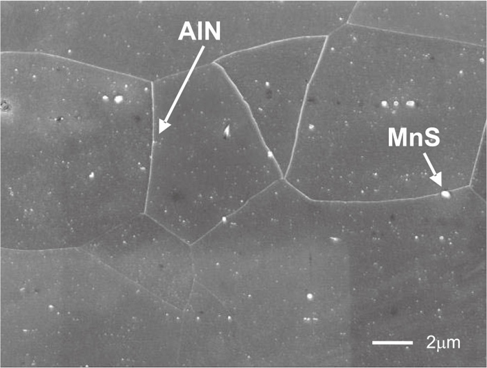
Lastly, a validation was carried out concerning the fine dispersion effect of the pinning particle. Figure 12 shows the macro-structure of cold-rolled and annealed steel sheet, in which AlN and MnS precipitated. It can be seen that the grain diameter is of the order of 10 μm, and the size of the pinning particles is of the order of 0.1 μm. This grain diameter ratio was set as a condition, and a simulation of the grain growth in the presence of pinning particles was carried out using a two-dimensional local curvature multi-vertex model. Figure 13 shows an example of the initial condition, as well as the end condition in which the grains have grown and are in equilibrium with each other (the condition in which the grains have stopped growing). The condition in which there are 100 grains over an area of 100×100 μm2 was defined as the initial condition. Here, to facilitate a comparison between the simulation and the actual material, units of length alone are indicated using the ordinary units of length. Consequently, the initial average grain radius becomes 5.6 μm. Also, the effective length Reff was set to 1 μm, the jumping energy EH was set to 10, the grain boundary energy γ per unit length was set to 1, the grain boundary minimum length Lmin was set to 0.7 μm, and the maximum length Lmax was set to 1.5 μm. The dispersion effect of fine particles was evaluated with various number and size of the pinning particles.
Setting the jumping energy EH to 10 is equivalent to setting only the 1st set of conditions. From Fig. 13, it can be seen that in the case where the total area fraction of the pinning particles is constant, the grains in the end condition become smaller as the pinning particles become finer.
Figure 14 shows the relationship between the radius Rg of the grains and the radius Rp as well as the area fraction fs of the pinning particles in the end condition obtained in the simulation. Figure 14(a) shows the grain radius Rg fitted by
R
p
/
f
s
1/2
, and Fig. 14(b) shows the grain radius Rg fitted by
R
p
/
f
s
2/3
. Here, because the initial grain radius in the simulation was set to approximately 5 μm, fitting was carried out by fixing the y-intercept to 5 μm in Fig. 14(b). It can be seen that Fig. 14(b) rather than Fig. 14(a) can be fitted using a high correlation function. When the improved Zener model24,25) is used, the index of fs is 1/2 in the case of two dimensions and 2/3 in the case of three dimensions. This proposed model is a two-dimensional model, but regarding the dispersion effect by the fine pinning particle, the results obtained were close to those of the three-dimensional improved Zener model. Regarding the prediction of the structure of metals, it is difficult to say that the grain growth in the presence of a pinning particle in an actual material is accurately reproduced. For this reason, it is necessary to perform additional studies in the future. However, because it has been confirmed that the change in the texture accompanying the grain growth in an actual material can be predicted qualitatively by taking into consideration the grain boundary characteristics,26) this model is expected to be useful for predicting the texture change during the grain growth in the presence of pinning particles.

Here, although the conditions used here were extremely exceptional conditions that did not originally exist, attention was focused on one crystal grain, and a simulation of grain growth in the presence of finely-dispersed particles was performed under the condition in which the grain boundary that surrounds the grain always has low energy. As shown in Fig. 15, abnormal grain growth in which only the grains surrounded by low energy grain boundaries grew selectively was confirmed. Here, as the simulation conditions, the number of pinning particles was set to 1000, the radius was set to 0.01, the effective length Reff was set to 5, the jumping energy EH was set to 0.02, the minimum length Lmin of the grain boundary was set to 0.7, the maximum length Lmax was set to 1.5, the energy of the grain boundary surrounding the grain of interest was set to 0.7, and the energy of the other grain boundaries was set to 1. Setting the jumping energy EH to 0.02 is equivalent to setting the 2nd set of conditions. In actual fact, when the adjacent grains disappear, the grain boundary energy γ per unit length changes, so this result does not realize selective growth. However, it can be said that this result indicates that under certain conditions specific grains can encroach on the adjacent grains.

4. Conclusions
A meso-scale pinning model for grain growth that can be used in the proposed two-dimensional local curvature multi-vertex model was proposed. This model is a physical model in which the grain boundary energy minimum is used as the evaluation function. In order to calculate the grain boundary energy, the effective range (the effective length Reff) was set. As a result of setting the effective length Reff, it is possible to realize a pinning model that does not rely on the minimum length Lmin of the grain boundary. The 1st condition for unpinning to occur is that the energy of the unpinned grain boundary in equilibrium be smaller than the energy of the pinned grain boundary. In addition, the 2nd condition was defined as the condition in which the grain boundary energy that initially increases when unpinning occurs becomes less than the newly introduced jumping energy EH.
In the proposed model, the 1st condition alone was set, enabling the fine dispersion effect of the improved Zener pinning model to be reproduced. In addition, the 2nd condition was also taken into consideration, thus enabling the abnormal growth of grains surrounded by low energy grain boundaries to be expressed.
Acknowledgements
We wish to express our sincere gratitude to Mr. Shunji Nishi of NS Plant Designing Corporation for his support in coding the simulator used in this research.
References
- 1) T. Suzuki, Y. Ishii, A. Itami, K. Ushioda, N. Yoshinaga and M. Tezuka: Mater. Sci. Forum, 204–206 (1996), 673.
- 2) Y. Ushigami, M. Mizokami, M. Fujikura, T. Kubota, H. Fujii and K. Murakami: J. Magn. Magn. Mater., 254–255 (2003), 307.
- 3) Y. Ushigami and T. Nakayama: Mater. Sci. Forum, 157 (1994), 1081.
- 4) M. P. Anderson, D. J. Srolovitz, G. S. Grest and P. S. Sahni: Acta Metall., 32 (1984), 783.
- 5) D. Fan and L. Q. Chen: Acta Mater., 45 (1997), 611.
- 6) H. J. Frost, C. V. Thompson, C. L. Howe and J. Whang: Scr. Metall., 22 (1988), 65.
- 7) H. J. Frost, C. V. Thompson and D. T. Walton: Acta Metall. Mater., 38 (1990), No. 8, 1455.
- 8) A. Soares, A. C. Ferro and M. A. Fortes: Scr. Metall., 19 (1985), 1491.
- 9) K. Kawasaki, T. Nagai and K. Nagashima: Philos. Mag. B, 60 (1989), No. 3, 399.
- 10) K. Fuchizaki, T. Kusaba and K. Kawasaki: Philos. Mag. B, 71 (1995), No. 3, 333.
- 11) D. Weygand, Y. Bréchet and J. Lépinoux: Philos. Mag. B, 78 (1998), No. 4, 392.
- 12) Y. Suwa: ISIJ Int., 52 (2012), No. 4, 582.
- 13) T. Tamaki, K. Murakami and K. Ushioda: Tetsu-to-Hagané, 101 (2015), No. 3, 211.
- 14) D. Weygand, Y. Bréchet and J. Lépinoux: Acta Mater., 47 (1999), No. 3, 961.
- 15) B.-N. Kim and T. Kishi: J. Jpn. Inst. Met., 62 (1998), No. 12, 1189.
- 16) A. Harun, E. A. Holm, M. P. Clode and M. A. Miodownik: Acta Mater., 54 (2006), 3261.
- 17) O. Hunderi and N. Ryum: Acta Metall. Mater., 40 (1992), No. 3, 543.
- 18) E. Nes, N. Ryum and O. Hunderi: Acta Metall., 33 (1985), 11.
- 19) M. Hillert: Acta Metall., 32 (1984), 3177.
- 20) C. J. Smith: Trans. Metall. Soc. A.I.M.E., 175 (1948), 15.
- 21) S. I. Wright and M. M. Nowell: Microsc. Microanal., 12 (2006), 72.
- 22) Y. Adachi: Bull. Iron Steel Inst. Jpn., 13 (2008), 676.
- 23) P. R. Rios: Acta Metall., 35 (1987), 2805.
- 24) F. J. Humphreys and M. Hatherly: Recrystallization and Related Annealing Phenomena, Pergamon Press, Oxford, (1995), 73.
- 25) T. Nishizawa, I. Ohnuma and K. Ishida: Mater. Trans., JIM, 38 (1997), No. 11, 950.
- 26) T. Tamaki, K. Murakami and K. Ushioda: ISIJ Int., 55 (2015), No. 3, 655.


