Regular Article
Numerical Analysis of Thermal Expansion of Rolls with Equivalent Heat Transfer Model on Circumference
2016 Volume 56 Issue 12 Pages 2243-2249

Details
2016 Volume 56 Issue 12 Pages 2243-2249
In hot strip rolling, the work roll shift method has been widely used to disperse thermal crown and wear of the work rolls in the axial direction. This paper provides a strategic control method for the work roll profile which surpasses the conventional work roll shifting method. A numerical simulation model which enables prediction of thermal crown and wear of work rolls with high accuracy has been developed, and a new shifting method has been proposed, focusing on the problems of the conventional shifting method.
In the conventional shifting method, the thermal crown within the contact area is calculated with a fixed cyclic stroke and step. In that case as the stroke increases, the average value of thermal crown in a rolling campaign decreases without concentration of heat input from the strip to the axial center of the work roll. However, as the stroke increases, the standard deviation of thermal crown during the campaign increases.
Although the work roll shift method is effective for dispersing work roll thermal crown and wear, the thickness profile of the strip is affected by the positional relationship between the work roll and the strip. Therefore, for further improvement of the work roll shift method, the need for a flexible shift method which considers the positional relationship between the work rolls throughout the entire rolling campaign is suggested.
Conventionally, hot rolling of steel sheet has been according to a coffin schedule in order to avoid the influence of thermal crown and wear of the work rolls (WR) on the strip thickness profile.1) However, slab sorting to the coffin schedule in the slab yard decreases productivity and increases heating furnace fuel consumption due to the lower slab insertion temperature at the furnace. Considering CO2 emission regulations for global warming and the need for energy saving in recent years, the improvement of the fuel consumption rate has been strongly desired in hot rolling process. Therefore, it is necessary to realize schedule-free rolling that makes it possible to roll a large number of hot strips and a random order of strip widths during a rolling campaign.2)
As a WR profile control method for schedule-free rolling, the WR shift method has been widely used to disperse roll wear and thermal crown in the axial direction of roll.3,4,5,6,7) In hot rolling, the WR shift is mainly applied to the latter stands in the finishing mill. Cyclical shifting of the WR in the axial direction of roll contributes to the expansion of schedule-free rolling.
In addition to dispersion of thermal crown and roll wear, the strip crown control method by using the WR shift was developed. Shifting the WR with an S-shape profile can control the roll gap by the shift position.8,9,10,11) These methods were mainly introduced in hot strip mills in Europe, then have spread to the developing countries recently.
In recent years, rolling efficiency has been improved due to highly precise mill pacing calculations and increased rolling speeds. However, as a result, the rolling intervals in finishing mills become shorter, and thermal crown behavior becomes more complicated than in the past.
High speed tool steel with hard carbides of V, Mo, W, Cr, etc. has been used for the WR. While these rolls provide improved wear resistance compared to conventional nickel grain rolls,12,13,14) the thermal conductivity and linear expansion coefficient of high speed steel rolls are higher and their thermal crown is larger than those of nickel grain rolls.15)
Thermal crown and roll wear have mutually offsetting effects which cancel out the change in the WR profile. However, a new control guideline for the WR shift is desired because the influence of thermal crown has increased due to shorter rolling intervals and expanded application of high speed steel rolls. Computational capabilities have also been improved, enabling exact online calculation of the WR profile.
In this study, we have developed a cyclic simulation model which describes the growth behavior of thermal crown strictly, and investigated the possibility of further development of WR profile control by the WR shift method.
The WR thermal crown is calculated as a two-dimensional problem, as shown in Fig. 1. The temperature distribution in the roll section is calculated by a heat conduction equation, as follows.
| (1) |

Cross-section view of WR for thermal crown calculation.
Thermal crown is calculated as the amount of thermal expansion based on the temperature distribution in the roll section by using the following equation.16)
| (2) |
The distribution of temperature in the roll section is calculated as a two-dimensional axial symmetry problem. The heat input from the hot strip and the cooling due to water and air cooling in the circumferential direction of roll are equalized as shown in Fig. 2.17,18) Namely, the following uniform heat input in the circumferential direction of roll in the strip path during the rolling and uniform cooling outside the strip path and during the rolling interval are assumed.
| (3) |
| (4) |

Boundary conditions of heat transfer.
To verify the accuracy of the thermal crown prediction model, the WR is extracted from the mill after the rolling campaign, and the diameter distribution is measured using a dial gauge. Thermal crown is defined as the difference between the measured profiles shortly after rolling and that after cooling to ambient temperature. The surface temperature is measured by a contact type thermometer.
Figure 3 shows the measured surface temperatures of the high speed steel roll used in F4 stand and the result calculated by the prediction model. Figure 4 shows the measured and calculated thermal crown profile.

Comparison of measured and calculated WR surface temperature.
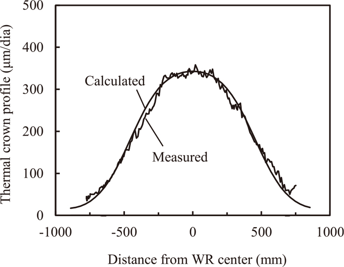
Comparison of measured and calculated thermal crown profile.
In the thermal crown calculation, the number of rolled strips, the strip width, the WR shift position and the cooling time after extraction are considered. The estimated error of the surface temperature is about 3% at the axial center of the roll. The estimated error of the WR thermal crown profile is about 3%. Thus, the accuracy of the thermal crown prediction model in this study is considered to be adequate.
The thermal crown behavior in the expansion of rolling campaign is analyzed. This is one challenge for productivity improvement in hot rolling. The wear of the high speed steel rolls used in recent years is very small compared with the amount of thermal crown. Therefore, this study focused on only the thermal crown behavior, assuming the use of the high speed steel rolls.
Here, the WR barrel length is 2000 mm, the roll radius is 400 mm and the neck radius is 200 mm as the average dimensions of WR in finishing mill. As shown in Fig. 5, the two WR are moved axially by a fixed shift pitch for every strip in the rolling campaign, and the direction of movement is reversed after reaching the shift stroke (shift turn point). The upper and lower WR move in opposite directions, and the shift stroke is fixed in a rolling campaign. When the rolling campaign starts, the roll axial center and the strip width center are the same. This setting method for the WR shift position has generally been used and is called “cyclic shift” in this paper.

Cyclic WR shift pattern (shift stroke: 600 mm, shift pitch: 15 mm).
Table 1 shows the WR shift conditions. The shift pitch is 15 mm, and the shift strokes are 150 mm, 300 mm, 450 mm and 600 mm. The strip width is 1000 mm and same width serial rolling is assumed as the cyclic condition.
| Shift pitch (mm) | 15 |
| Shift stroke (mm) | 150, 300, 450, 600 |
| Rolling time (s) | 100 |
| Interval (s) | 10, 20, 30 |
A “rolling time” is defined as the time during which the WR is in contact with the strip, and the “rolling interval” is defined as the time from the end of the former strip rolling to the start of next strip rolling. The rolling time of each strip is set to 100 s and is fixed in the campaign. Calculations are performed for three rolling interval conditions, 10 s, 20 s and 30 s.
3.2. Results of Analysis 3.2.1. Evaluation of Thermal CrownTo estimate the influence of the thermal crown profile on the strip thickness profile in the width direction, the evaluation index TCR25 is defined as the difference of the thermal crown per diameter between the strip width center and the point 25 mm from the strip edge, as shown in the following equation.
| (5) |
Tcenter shows the thermal expansion amount per roll diameter at the strip center, and TE25 is that at the point 25 mm from the strip edge. Figure 6 shows the change in thermal crown as a function of the rolling campaign (shift stroke: 600 mm). The thermal crown at the roll center in the axial direction increases gradually, but TCR25 fluctuates periodically and widely. As an index of the magnitude and dispersion of thermal crown, for the analysis hereafter the average value and standard deviation between the 70th and 200th strips is used, since the thermal expansion at the WR center is approximately saturated after rolling the 70th strip.
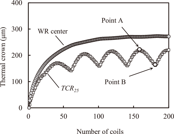
Evaluation of thermal crown of cyclic WR shift (shift stroke: 600 mm, shift pitch: 15 mm).
Figure 7 shows the relationship between the average value and standard deviation of thermal crown at each rolling interval. The symbols indicate the shift strokes. As shown in Fig. 7, the average value and standard deviation of thermal crown increase as the rolling interval decreases because the thermal expansion at the strip center increases as cooling time decreases. This is also indicative of the complexity of thermal crown behavior in the short interval strip rolling of recent years.

Relation between average and standard deviation of thermal crown (cyclic WR shift).
At the same rolling interval, the average value of thermal crown decreases as the shift stroke becomes larger because the WR profile becomes smooth in the axial direction, without concentration of heat input at the WR center in the axial direction. Conversely, a longer shift stroke results in a larger standard deviation of the thermal crown.
According to Fig. 7, in order to reduce the influence of thermal crown on the strip thickness profile by cyclic WR shift, a longer shift stroke has the effect of reducing the average value of thermal crown. However, the longer shift stroke also leads to a larger standard deviation of thermal crown and may cause the deterioration of the strip thickness profile, depending on the WR shift position. This is one of the problems of the conventional cyclic shift method. The consideration of the dispersion of thermal crown will be presented later.
The problem of the conventional cyclic WR shift method has been pointed out in width change rolling for schedule-free rolling. The width change rolling after same width serial rolling is assumed as the rolling campaign for analysis. The strip width in same width rolling is 1000 mm and that in width change rolling is 1200 mm.
The thickness profile in the width direction is calculated by a model considering the elastic deformation of the rolls19,20) in order to estimate the influence of the WR profile on the thickness profile. The F4 stand in the 7 stand-finishing mill is assumed. The inlet thickness at the width center is 5.5 mm, and the outlet thickness is 3.8 mm. The rolling load is 14000 kN and the WR bending force is 600 kN per chock. The inlet crown is 40 μm at the point 25 mm from the strip edge. The inlet thickness distribution in width direction is approximated by the quadratic function. Lateral strain is ignored, and the plane strain state is assumed.
4.2. Analysis ResultsFigure 8 shows the thickness profile in width change rolling. The positions of the WR axial center and the strip width center are the same (WR shift position is zero). The thickness at the strip edge is larger than that inside the edge. This is called “edge buildup,” and leads to the flatness defect in the following rolling process and the embedded defect in coils. As shown in Fig. 9, the edge build-up is caused by the WR thermal crown profile, axial deflection and surface flattening.

Calculated thickness profile of strip width change rolling.

Mechanism of edge buildup profile.
The thickness profile of the width change rolling after 20 more coils of the same width rolling is also shown in Fig. 8. The WR shift position is −300 mm. In this case, the buildup profile is not formed. This indicates that the influence of the WR profile on the thickness profile is different depending on the WR shift position (that is, the rolling order in width change rolling), even under the same WR shift condition.
Firstly, the dispersion of the thermal crown in same width serial rolling is discussed. Coils in which TCR25 has local maximum and minimum values in Fig. 6 are focused on. Figures 10(a) and 10(b) show the thermal crown profile of the upper and lower WR when TCR25 displays local maximum and minimum values, respectively. The WR shift position in Fig. 10(a) is 0 mm, and that in Fig. 10(b) is 300 mm. The horizontal axis is the distance from the strip center.

Thermal crown profile of same width serial rolling.
In both cases, the peak point where the thermal crown shows maximum value in the axial direction is located at the WR axial center. However, the peak point is located near the strip center in Fig. 10(a) and near the strip edge in Fig. 10(b). The thermal expansion values at each peak point are almost the same, being 270 μm in Fig. 10(a) and 273 μm in Fig. 10(b). The sum of the upper and lower WR thermal crowns is shown in Fig. 10 by the dotted line. The sum of the thermal crowns of the upper and lower WR when the WR shift position is 0 mm is larger than when the WR shift position is 300 mm. This is due to the positional difference between the peak points of the thermal crown and the strip, since the thermal expansion at the peak point in Fig. 10(a) is almost same as in Fig. 10(b). In Fig. 10(a), the difference of the thermal crowns at the strip center and edge is large (i.e., the influence on the thickness profile is significant), since the peak point is located near the strip center. Whereas in Fig. 10(b), there is only a small difference in the thermal crowns at the strip center and edge, since the peak point is located near the strip edge. Therefore, the variability in same width rolling is due to the WR shift position, and not the thermal expansion value.
Figure 11 shows the calculated thermal crown profile in the axial direction of WR. Figures 11(a) and 11(b) show the upper and lower WR profiles when the WR shift position is 0 mm and −300 mm, respectively. In these two cases, the maximum value of thermal crown in the axial direction is 272 μm, and both values are the same. However, there is a difference in TCR25 in Figs. 11(a) and 11(b), which are 352 μm and 278 μm, respectively. The sum of the upper and lower WR thermal crowns is shown in Fig. 11 by the dotted line. Although the maximum value of the thermal crown in the axial direction is the same, there is a difference on the influence on strip thickness profile, which is caused by the WR shift position.

Thermal crown profile of width change rolling.
Hence, on controlling the WR profile by the WR shift, it is suggested that the positional relationship between the WR and strip is also important, in addition to the dispersion of thermal crown. With the conventional WR shift method, the long WR shift stroke can secure a smooth WR profile in the axial direction and decrease the average value of thermal crown. However, the WR shift position is inappropriate, and thermal crown may have the significant influence on strip thickness profile in some rolling orders due to the fixed shift pitch in a rolling campaign. This is the reason for thermal crown fluctuations.
5.2. Possibility of Improvement of Thermal Crown Control CapabilityIn the same width serial rolling by the conventional WR shift method, when the WR shift position is maximum and zero, TCR25 is minimum and maximum, respectively. Therefore, in order to decrease both the average value and standard deviation of thermal crown, application of a variable shift pitch and rolling of many strips near the shift turn point are considered to be effective. As one example, Fig. 12 shows a shift pattern in which the shift position change is 450 mm in every 7 strips. Figure 13 shows the calculated results by the shift pattern in Fig. 12. Compared to the conventional cyclic shift (fixed shift pitch: 15 mm), both the average value and standard deviation of thermal crown are small.

WR shift pattern of variable shift pitch.

Relation between average and standard deviation of thermal crown (variable pitch).
Hence, in the same width serial rolling, the WR shift with a variable shift pitch can increase the thermal crown control capability.
In the width change rolling, the conventional cyclic shift has a different influence on the thickness profile depending on the shift position, even if the maximum value of the thermal crown in the width direction is the same. Therefore, there is an appropriate shift position to inhibit the influence of thermal crown in width change rolling.
Figure 14 shows the thermal crowns when the WR shift position is changed from that position planned by the cyclic shift pattern. The influence of the thermal crown varies with the WR shift position. The influence is large at near 0 mm and small at near ±300 mm because the peak point is located at the strip width center when the shift position is near 0 mm, but is located at the strip width edge when the shift position is near ±300 mm, as is also the case in the same width serial rolling.

Influence of WR shift position on thermal crown (shift stroke: 600 mm).
As shown in Fig. 14, TCR25 shows its maximum value when the shift position is about 60 mm. In Fig. 14, TCR25 is asymmetric on the WR shift position. Heat input and cooling area on the WR surface changes periodically by the axial movement. As a result, the thermal crown profile shown in Fig. 11(a) is asymmetric. Under these analysis conditions, the minus side (A) of the upper WR contacts the strip for longer time than the plus side (B). Therefore, the thermal crown on the WR minus side is larger than that on the plus side (B). Hence, when the WR shift position changes from the position planned by the cyclic shift pattern, TCR25 shows its maximum value at the plus side WR shift position. To minimize the influence of WR thermal crown, −300 mm is optimal when TCR25 is minimum.
In the width change rolling, it is possible to control thermal crown appropriately by using the different shift position from the position planned by the cyclic shift pattern. This is equivalent to controlling the shift position by considering the thermal crown profile as the WR gap control, in addition to the dispersion effect of the conventional cyclic shift method.
In this study, the rolling time and cooling intervals are set constant in the same width serial rolling and width change rolling. However, in actual hot rolling, the strip width, rolling time, cooling time and rolling length are random during a rolling campaign. Therefore, it is necessary to set the WR shift positions with flexibility, considering not only the positional relationship between the WR profile and the strip during width change rolling, but also the influence on the WR profile after width change rolling.
A cyclic simulation model has been developed to predict thermal crown with high accuracy, and the thermal crown behavior in hot rolling of steel sheet has been evaluated.
(1) In the conventional cyclic shift, extending the shift stroke decreases of the average value of thermal crown and increases the standard deviation. A longer shift stroke may cause deterioration of the strip thickness profile, depending on the WR shift position.
(2) To improve the WR profile control capability, it is necessary to set the WR shift position considering the positional relationship between the WR and the strip, in addition to the conventional effect of dispersing thermal crown.
(3) In same width serial rolling, it is possible to decrease both the average value and standard deviation by adopting the variable shift pitch method.
(4) In the width change rolling, the WR shift position different from the planned cyclic position makes it possible to control the influence of thermal crown on the thickness profile.