Regular Article
Optimal Design for Cooling System of Hot Stamping Dies
2016 Volume 56 Issue 12 Pages 2250-2258

Details
2016 Volume 56 Issue 12 Pages 2250-2258
Cooling system design is one of the key technologies for the hot stamping process, and the properties and the production efficiency of the advanced high strength hot-stamped parts are greatly influenced by the cooling performance of the hot stamping dies. In this paper, a new selection criterion for the cooling channel parameters including the channel diameter, the number of the channels and the distance from the channel center to the die contact surface was developed, and a cooling channel structure optimization method based on the difficult degree of cooling was proposed. Using the criterion, cooling channels of the hot stamping dies for an anti-collision beam were designed, and the effect of the designed cooling systems was measured according to the cooling intensity, uniformity and the die strength by simulation. Based on the simulation results, the structure of the cooling channels was optimized. Results show that all the cooling systems designed based on the cooling channel design method can meet the requirements of the cooling intensity and the die strength, while cooling systems with smaller cooling channel diameter are recommended to be the better choices in terms of the cooling uniformity. In addition, the cooling uniformity and intensity of the cooling system optimized based on the difficult degree of cooling can be both improved. According to the simulation results, the hot stamping dies for the anti-collision beam were manufactured, and the high quality hot stamped part was achieved, which proved the rationality of the cooling channel design method.
In recent years, hot-stamped components with advanced high strength have been more and more widely used in car body manufacturing for the advantageous properties such as high strength-to-weight ratio and good crash behavior, which enable the possibility of weight reduction and enhancing passenger safety at the same time.1,2,3) In the production of hot-stamped components, the initial blank with ferritic-perlitic microstructure is heated to completely austenitic state firstly, and then formed and quenched in the closed dies.4,5) The rapid cooling in the hot stamping dies results in the transformation from austenite to martensite. The martensitic microstructure provides the final part with an ultra high strength up to 1500 MPa.6) To achieve rapid cooling, a cooling system is essential to be integrated into the hot stamping dies.
Cooling system design of the hot stamping dies significantly influences not only the cooling performance of the dies and the properties of the final part, but the production efficiency and the service life of the dies as well. To improve the cooling performance of the hot stamping dies, several studies have been conducted. Steinbeiss et al.7) presented a specific evolutionary algorithm to design the hot stamping dies with cooling systems with the help of finite element analysis. Lim et al.8) proposed a cooling channel design method based on the energy balance principle, the triangular method, tool split, and the connection rule for 2D sections, and applied the design method to hot stamping dies for a roof side automotive part using two separate approaches. Lin et al.9) introduced a thermal-fluid-mechanical coupled simulation method by use the softwares of Fluent, Abaqus and MpCCI. Xu et al.10) studied the cooling channel structure parameters such as cooling channel size, distance between cooling channels, and depth from cooling channel to die surface using heat transfer theory, and provide a theoretical reference for hot stamping die design. Shan et al.11) studied the cooling system design through analysis of phase transformation of stamping parts, die structure strength and deformation requirements of die and stamping parts. Liu et al.12) investigated the optimization method of the cooling system of hot stamping dies, and manufactured two different sets of dies used to manufacture square-box-shaped part and B pillar using drilling method and pre-embedding method, respectively.
So far, selection of the parameters for most cooling channels of the hot stamping dies is based on experience, and few studies have been conducted on the structure design of the cooling system. Consequently, the main objectives of this paper are to establish a calculation criterion for the cooling channel parameters selection, and to offer an optimization method for the cooling channel structure. To achieve the purposes of this paper, a series of formulas for calculating the cooling channel parameters were established, and a cooling channel structure optimization method based on the difficult degree of cooling was proposed. The selection criterion and the structure optimization method were applied to the hot stamping dies for an anti-collision beam and high quality hot stamped part was achieved, which proved the rationality of the cooling channel design method in this paper.
Design of the cooling system has an important influence on the properties of the hot-stamped part and the working life of hot stamping dies. For example, cooling system with closer cooling channels is advantageous to improve the cooling performance, but weaken the die strength. Therefore, a reasonable cooling system design should not only take the cooling performance but also the die strength into consideration. In this work, the cooling channel diameter d, the number of the channels n, and the distance from the channel center to the die contact surface δ are chosen as the key parameters for the cooling system design, as shown in Fig. 1.
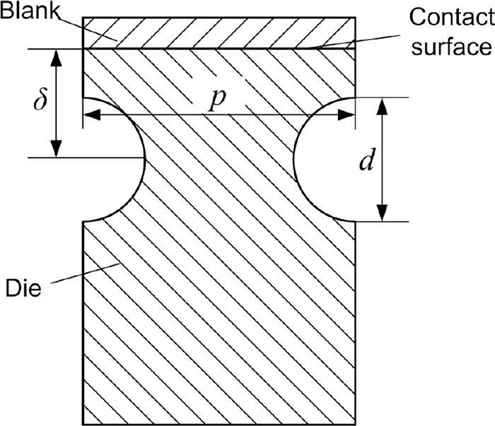
Simplified cooling system model.
During the cooling process in hot stamping, martensitic transformation occurs, in which latent heat will be released. Therefore, the heat released by the blank during quenching consists of both the heat loss due to the temperature reducing and the latent heat loss. The total heat loss of the blank during quenching QB in a cooling circle can be calculated as follows:
| (1) |
Assuming the heat absorption efficiency of the cooling water is φ, the heat absorbed by the water QW can be calculated as
| (2) |
| (3) |
| (4) |
| (5) |
| (6) |
| (7) |
| (8) |
| (9) |
To ensure the turbulent flow in the cooling channels, the Reynolds number Re for the flowing water should be above 4000. However, if Re is larger than 10000, the total heat transfer rate decreases.8) Hence, the proper range for Re is 4000 ≤ Re ≤ 10000. According to the calculation equation for Re:
| (10) |
| (11) |
As known from the aforementioned analysis, the proper cooling channel diameter d can be chosen following the formulas below:
| (12) |
To achieve sufficient cooling performance, the total surface area of the cooling channels AC should be larger than the contact surface area of the blank AB:13,14)
| (13) |
| (14) |
Consequently, the distance between the adjacent channel centers p can be determined based on the width of the part and the number of the channels.
2.3. Distance from the Cooling Channel Center to the Die Contact SurfaceThe heat flux through the dies Φ can be calculated as:
| (15) |
| (16) |
| (17) |
| (18) |
| (19) |
| (20) |
| (21) |
| (22) |
Actually, the contact between the blank and the dies is insufficient, and the thermal contact resistance exits between the blank and the dies although the value is small. Therefore, to achieve adequate cooling, the distance δ should be smaller than the value calculated from Eq. (22). Thus, the proper distance from the channel center to the contact surface of the dies δ should meet the range as follows:
| (23) |
Lim et al.8) summarized a method for judging the strength of the hot stamping dies with cooling channels installed by using a stress factor (SF):
| (24) |
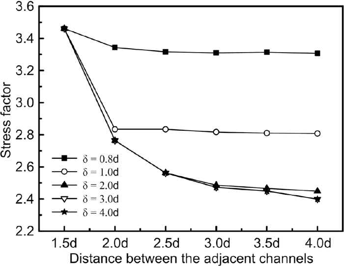
Stress factor diagram relating to various dimensions.
In this article, the section of an hot stamped anti-collision beam was chosen as an example to exhibit the optimization method for the the cooling channel design. The anti-collision beam and the typical section are shown in Fig. 3.
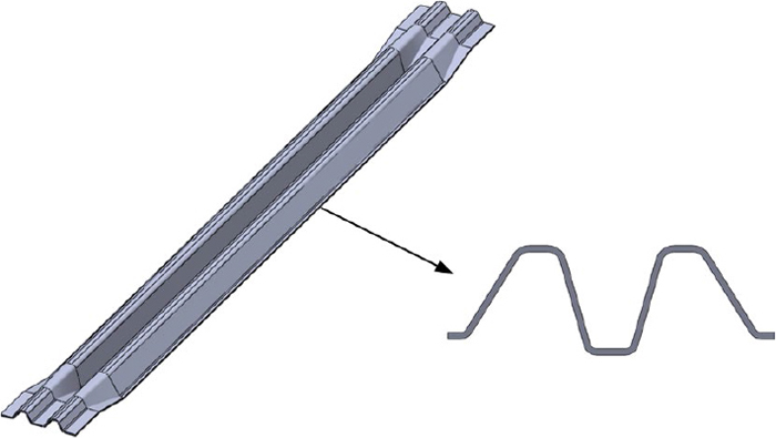
Part model and cross section characteristics. (Online version in color.)
The detailed input datum for calculating the cooling channel parameters and the computing results are shown in Table 1. It can be gained from Eq. (12) that the proper cooling channel diameter is 8–20 mm. When the diameter is 20 mm, the channel number is 10 according to Eq. (14). Thus, the maximum distance between the adjacent channel centers is 30 mm considering the die width, so δ = 1.5d. As known from Fig. 2, the stress factor is 3.46 when the minimum distance from the channel center to the die contact surface is 0.8d. Due to that the yield stress for the die material H13 at 200°C is approximately 1000 MPa,16) the maximum contact pressure is 289.02 MPa, which can be calculated from Eq. (24). As calculated from Eq. (23), the maximum distance from the channel center to the die contact surface is 30 mm when the channel diameter is in range of 8–20 mm. Therefore, the proper distance from the channel center to the die contact surface is 0.8d ~30 mm.
| Parameters | Values | |
|---|---|---|
| Input datum | ||
| Blank mass mB ( kg ) | 0.42 | |
| Blank length LB ( m ) | 0.15 | |
| Blank width WB ( m ) | 0.18 | |
| Blank thickness tB ( m ) | 0.002 | |
| Initial blank temperature TB,1 (°C ) | 800 | |
| Final blank temperature TB,2 (°C ) | 200 | |
| Average blank special heat Cp,B ( J·kg−1·°C−1 ) | 550 | |
| Blank latent heat L ( J·kg−1 ) | 85000 | |
| Water special heat Cp,W ( J·kg−1·°C−1 ) | 4187 | |
| Water flowing speed v ( m·s−1 ) | 0.5 | |
| Water density ρW ( kg·m−3 ) | 998.2 | |
| Initial water temperature TW,1 (°C ) | 20 | |
| Final water temperature TW,2 (°C ) | 50 | |
| Water viscosity coefficient ηW ( kg·s·m−2 ) | 0.001 | |
| Heat absorption efficiency φ | 0.9 | |
| Cooling channel length l ( m ) | 0.1 | |
| Ratio AC to AB α | 1.67 | |
| Die thermal conductivity λD ( W·m−1·°C−1 ) | 38 | |
| Cooling circle time tC ( s ) | 8 | |
| Output datum | ||
| Cooling channel diameter d ( m ) | 8–20 | |
| Number of cooling channels n | 24–10 | |
| Distance from the channel center to die contact surface δ ( m ) | 0.8d ~30 | |
| Die contact pressure ( MPa ) | ≤289.02 | |
As known from Table 1, the proper range for cooling channel diameter is 8–20 mm. To analyze the effectiveness of the computing results, simulation analysis was done relating to different cooling channel diameters. The selected channel diameters were 8, 10, 12, 14, 16 and 20 mm. Based on the values of the channel diameters, the simulation models were divided into six groups, as shown in Fig. 4. The total surface area of the channels was almost same for all the groups. To enhance the die strength, the values of δ were all 1.25d. The channels were arranged conformably along the shape of the contact surface curve. The gaps between the channels in each solution were tried to keep consistent respectively.
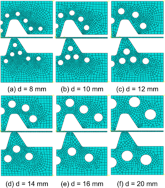
Simulation models for the cooling systems designed based on the cooling channel selection criterion. (Online version in color.)
The thermo-mechanical simulations were conducted with a general finite element software ABAQUS 6.12. The material of the blank was 22MnB5. The material property parameters were obtained from the literature.9,17) To simulate the forming and quenching process accurately, temperature and strain rate dependent flow stress curves, pressure and clearance dependent heat transfer coefficient, and temperature dependent thermal conductivity and specific heat were used. In addition, latent heat was also considered. The algorithm type for the simulation step was dynamic, temp-disp, explicit, and no acceleration was used in the steps. The friction at the interfaces was represented by a classical Coulomb model, assuming μ = 0.3. The global mesh size of the blank was 1 mm, while the size for the dies was 5 mm with local 1 mm refinement. The mesh types were all CPE4RT. The upper die moved down at the speed of 100 mm/s during forming and the lower die was fixed all the time. The pressure imposed to the die during the quenching stage was 1×10⁷ N/m. The holding time during quenching for all the models was 8 s. Due to section consistency and symmetry, a 2D half model was reasonable.
It should be noted that the simulation models above were applied for the single piece production. For continuous hot stamping in mass production, the temperature of the dies and the cooling water increases gradually. To overcome the problem of the die temperature increasing, the cooling system of the continuous hot stamping dies can be designed based on the severest situation. In continuous hot stamping, the temperature of the dies and the cooling water will increase to a steady temperature range after some cycles.12) This temperature increase will influence the input datum of the initial water temperature TW,1 and the final water temperature TW,2. The temperature range is influenced by the hot-stamping production cycle. The values of the temperature range are higher when there are more strokes per minute. The highest values of the temperature range occur when there is no time interval in two adjacent strokes, and this is the severest situation for quenching. Hence, for continuous hot stamping, the value of TW,1 and TW,2 can be the minimal and maximal temperatures of the steady range for the situation that there is no time interval in two adjacent strokes. Besides, the value of stress factor in mass production should be higher than that in the single piece production, to make sure the high strength of the dies. If the cooling effect of the designed cooling system can meet the requirements of the severest situation, the corresponding cooling system will be reasonable.
3.2. Simulation Results and AnalysisFigure 5 shows the temperature distributions of the parts quenched with different cooling channel parameters. The cooling rates of the nodes in the middle position of the parts where the temperature dropped most slowly evolving with temperature falling during quenching are plotted in Fig. 6. It can be seen from the figures that the temperatures of the parts cooled by all the cooling system dropped to 200°C in the prescribed time, and the cooling rates were almost all above 27°C·s−1, which is the critical cooling rate for martensitic transformation.4) Figure 7 shows the maximum contact pressure distributions of the die surfaces during the forming process. It can be seen that the maximum contact pressures in different cooling channel conditions were all in the safe range. Therefore, in terms of cooling intensity and die strength, the calculation models for the cooling channel parameters are reasonable.
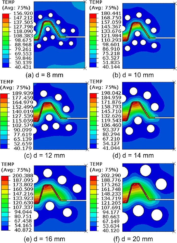
Temperature distribution results after 8 s quenching for different cooling channel conditions. (Online version in color.)
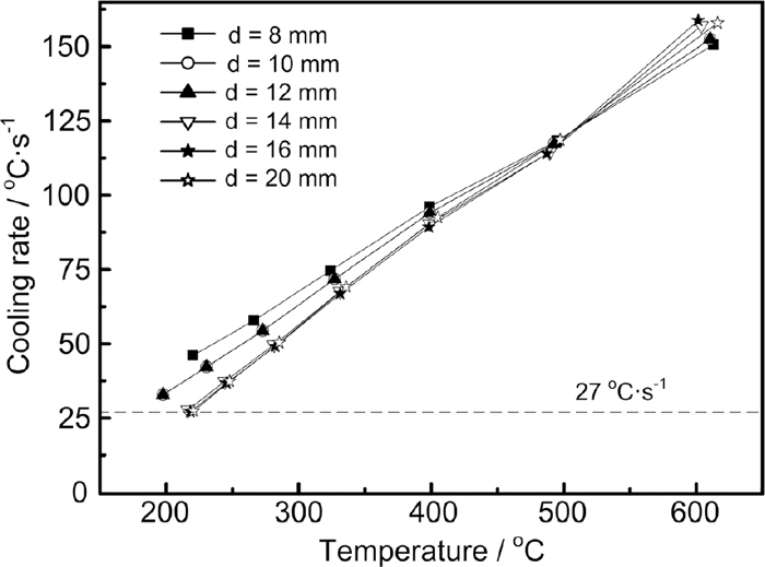
Variations of cooling rates during quenching for different cooling channel conditions.
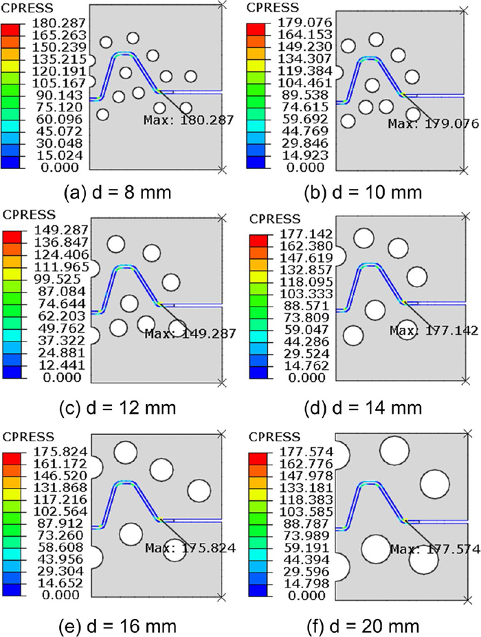
Contact pressure distribution results of the dies at the end of stamping for different cooling channel conditions. (Online version in color.)
It can also be concluded from Fig. 5 that the temperature distribution of the parts is not identical for different cooling channel parameters. Temperatures of the nodes in the middle layer of the section were measured as shown in Fig. 8. Based on the temperature datum in Fig. 8, the statistics relating to the cooling uniformity of the components were calculated, as presented in Table 2. It can be known that when the area of the cooling channels were limited, solutions with smaller channel diameters were more favorable to improve the cooling uniformity, as well as the cooling intensity. This is due to that smaller channels can be arranged more closely not only with each other but also to the die surface in same die strength condition.
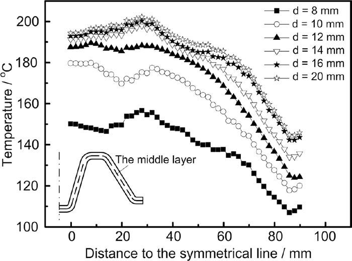
Temperatures of the nodes in the middle layer of the section after 8 s quenching for different cooling channel conditions.
| Cooling channel diameter/mm | Standard deviation/mm | Average temperature/°C | Difference between the maximum and the average temperature/°C | Difference between the minimum and the average temperature/°C |
|---|---|---|---|---|
| 8 | 14.55 | 139.10 | 17.74 | 32.44 |
| 10 | 19.62 | 159.84 | 19.94 | 42.61 |
| 12 | 20.93 | 170.93 | 18.63 | 47.13 |
| 14 | 19.67 | 177.87 | 20.11 | 44.58 |
| 16 | 16.98 | 182.29 | 18.04 | 40.84 |
| 20 | 16.82 | 184.88 | 17.35 | 40.97 |
In summary, all the cooling systems designed based on the selection criterion for the cooling channel parameters can meet the requirements of the cooling intensity and the die strength, while cooling systems with smaller cooling channel diameters are recommended to be the better choices in terms of the cooling uniformity.
It can be known from the above analysis that the differences between the peak temperature and the average temperature in all the solutions were more than 30°C, even for the optimal solution with 8 mm channel diameter. This inconsistency in temperature falling was not beneficial for the improvement of production efficiency and performance uniformity of the hot stamped parts. Hence, the cooling system needs to be further optimized, which can be achieved by adjusting the cooling channel arrangement. When the channels were arranged in a basically consistent gap, the heat in the middle of the components was relatively difficult to be absorbed, and the cooling performance in the middle was significantly weaker than that at the ends. Therefore, in this article, the cooling system structure would be optimized by adjusting the cooling channel arrangement based on the difficult degree of cooling. The method would be introduced in the following with the example of the solution with 8 mm channel diameter.
Firstly, divide the difficult degree of cooling into three levels according to the temperature distribution of the part quenched in the condition the channels were arranged uniformly, as shown in Fig. 9. Level 1 is correspond to the regions of the part which are most difficult to be cooled. Usually these regions are in the middle of the part. Level 3 is related to the regions which are easiest to be cooled, and the corresponding regions are at the ends of the part generally. The regions in level 2 are the transition areas between the regions in level 1 and level 3. Afterwards, for the regions in level 1, decrease the gap between the channels to increase the channel number in this region, and shorten the distance from the channel center to the die contact surface under the premise of ensuring the die strength; for the regions in level 2, just shorten the distance from the channel center to the die contact surface; for regions in level 3, no changes will be made.
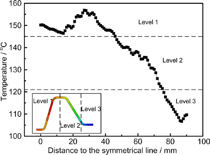
Difficult degree of cooling of the parts quenched by cooling channels with constant channel gap and distance to the die surface. (Online version in color.)
The optimized cooling channel structure for the solution with 8 mm channel diameter is shown in Fig. 10(c). In the optimized cooling system, the channel gap in the regions in level 1 was decreased, the channel number in this regions was increased, and the distance from the channel center to the die surface was shortened from 1.25d to 1.0d, while only the distance from the channel center to the die surface was shortened from 1.25d to 1.0d in the regions in level 2, and no change was done in the regions in level 3. To investigate the cooling uniformity of the dies with optimized cooling system, the temperatures of the die surface and the part after 8 s quenching were collected and compared in three conditions, which were the dies without cooling system, the dies with cooling system not optimized in structure and the dies with cooling system optimized in structure. The simulation models for the three conditions are shown in Fig. 10, the simulation results are shown in Fig. 11, and the comparison results are presented in Fig. 12 and Table 3. The datum in Figs. 10(b) and 11(b) are in consistent with Figs. 4(a) and 8 respectively. The comparison results in Fig. 12 and Table 3 are based on the datum in Fig. 11. It can be seen from the comparison results that after the cooling system of the hot stamping dies was optimized with the method in this article, the differences between the peak temperatures of the die surface and the part both became smaller, and the uniformity of the temperatures of the die surface and the part were both improved. Besides, the temperatures of the whole system reduced as well, which illustrated that the cooling intensity was improved as well.
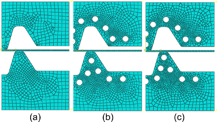
Simulation models for different forming conditions: (a) Dies without cooling system, (b) Dies with cooling system not optimized in structure, (c) Dies with cooling system optimized in structure. (Online version in color.)
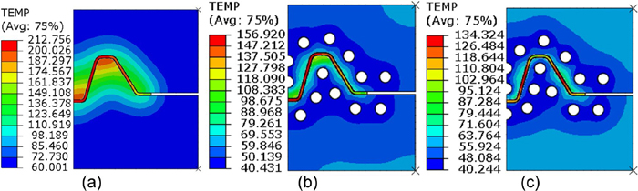
Temperature distribution results after 8 s quenching for different forming conditions: (a) Dies without cooling system, (b) Dies with cooling system not optimized in structure, (c) Dies with cooling system optimized in structure. (Online version in color.)
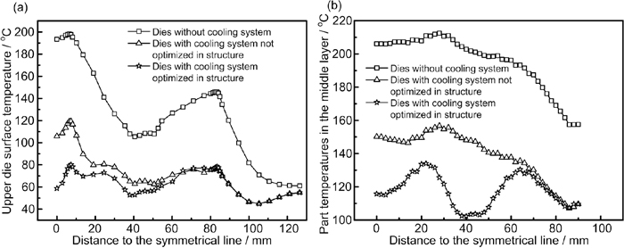
Comparison results of the temperatures of the die surfaces (a) and the parts (b) after 8 s quenching for different forming conditions.
| Forming conditions | Standard deviation/mm | Average temperature/°C | Difference between the maximum and the average temperature/°C | Difference between the minimum and the average temperature/°C |
|---|---|---|---|---|
| Dies without cooling system | 16.38 | 194.94 | 17.56 | 37.52 |
| Dies with cooling system not optimized in structure | 14.55 | 139.10 | 17.74 | 32.44 |
| Dies with cooling system optimized in structure | 9.51 | 117.86 | 16.35 | 16.01 |
In actual production, production efficiency is an important factor that an enterprise must consider. For hot stamping, the parameter of stroke per minute (SPM) is usually used to measure the production efficiency. The production efficiency datum in different forming conditions are presented in Table 4. In this table, assuming that the blanks have been heated to the given temperature, so the time of single hot stamping circle ignores the heating time, and only includes the stamping time, the quenching time, and the time needed for the die surface temperature cooling to the room value. It can be seen from Fig. 12 and Table 4 that even though the temperature of the part stamped by dies without cooling system in a single press could fall to almost 200°C after 8 s quenching, the temperature of the die surface was high. The high die surface temperature would increase the time between two adjacent hot stamping circles and decrease the strokes per minute, which discouraged the production efficiency. However, after the cooling system was optimized, the die surface temperature after quenching decreased obviously, the interval time reduced evidently, and the SPM increased more than two times from 1.98 to 4.87. Therefore, the cooling system design method in this work can improve the SPM of hot stamping substantially.
| Forming conditions | Time for stamping and quenching/s | Maximum die surface temperature after quenching/°C | Time for die surface temperature cooling to room value/s | Time of single hot stamping circle/s | SPM |
|---|---|---|---|---|---|
| Dies without cooling system | 8.32 | 198.10 | 22 | 30.32 | 1.98 |
| Dies with cooling system not optimized in structure | 8.32 | 119.40 | 8 | 16.32 | 3.68 |
| Dies with cooling system optimized in structure | 8.32 | 80.17 | 4 | 12.32 | 4.87 |
As known from the simulation results, the cooling performance of the cooling system with smaller channel diameter is better, and the cooling channels should be arranged according to the cooling difficult degree of the corresponding regions. Based on the above analysis, the hot stamping dies for a miniaturized anti-collision beam were manufactured, as shown in Fig. 13. The channel diameter of the dies was 8 mm, and the channels in the middle region of the section were more concentrate and closer to the die surface. Using the designed dies, hot stamping tests were conducted, as shown in Fig. 14. The temperatures of the die surface and the part after 8 s quenching in test were measured by infrared thermometer. The temperature datum in test were compared with the corresponding simulation datum, as seen in Fig. 15. The consistency of test and simulation results verified the accuracy of the simulation results. The simulation and test results in Figs. 11, 12, 13, 14, 15 and the datum in Table 3 proved that the temperature distribution of the die surface after quenching by the single press was almost uniform. The microstructure and the mechanical properties of the formed part were also measured. Results show that the microstructure of the part was complete martensite phase (Fig. 16), the strength was 1502.4 MPa, and the hardness was 501.7 HV. The high quality hot stamped part proved the rationality of the cooling channel design method.
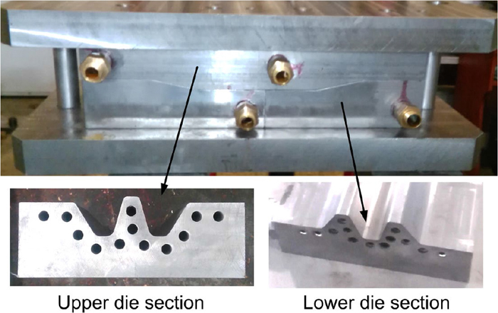
Hot stamping dies. (Online version in color.)
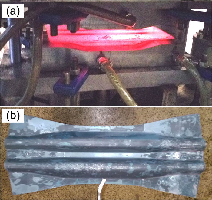
Hot stamping test (a) and hot stamped part (b). (Online version in color.)
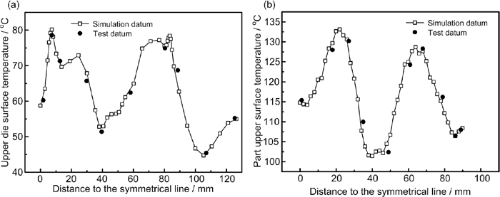
Temperature comparison of the die surfaces (a) and the parts (b) after 8 s quenching between the test and the corresponding simulation results.
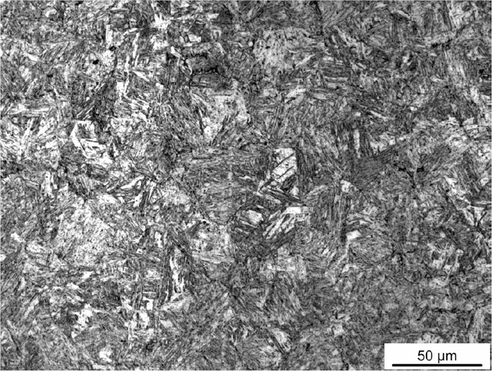
Microstructure of the hot stamped part.
In this paper, a selection criterion for the cooling channel parameters of the hot stamping dies including the channel diameter, the number of the channels and the distance from the channel center to the die contact surface was established not only considering the cooling performance but the die strength as well. Based on the criterion, cooling channel models of the hot stamping dies for an anti-collision beam were developed. The cooling performance of the designed cooling systems was analyzed by simulation, finding that all the cooling systems designed based on the selection criterion can meet the requirements of the cooling intensity and the die strength, while cooling systems with smaller cooling channel diameters are recommended to be the better choices in terms of the cooling uniformity.
In addition, the cooling channel arrangement can be optimized based on the difficult degree of cooling. According to the temperature distribution of the part quenched by equally arranged cooling channels, different cooling degrees can be divided. For the regions of the parts which are most difficult to be cooled, smaller channel gaps and distances from the channel center to the die contact surface and more channels are recommended, under the precondition of guaranteeing the die strength. For the regions which are relatively more difficult to be cooled, only smaller distances from the channel center to the die contact surface are needed. For the regions which are easy to be cooled, no changes should be done.
In practical application, the cooling channels of the hot stamping dies can be designed by two steps. Firstly, determine the values of the cooling channel parameters. Based on the calculation criterion established in this paper, the proper range for the cooling channel parameters can be obtained, while the schemes with smaller cooling channel diameters are recommended. Secondly, determine the arrangement scheme of the cooling channels. The cooling channel can be arranged based on the difficult degree of cooling, and the combination of numerical simulation should be conducted, which can present the cooling effect of the designed cooling system rapidly and intuitively.
This work was supported by the Major Technology Program of Ministry of Industry and Information Technology of P.R.China (NO. 2009ZX04014-072-01), the National Youth Science Fund Project (NO. 51301074) and the Technology Development Program of Jilin Province (NO. 20130102021JC).