Abstract
In this study, diamond-like carbon (DLC) films are prepared by DC-pulsed plasma-enhanced chemical vapor deposition (PECVD) after the oxynitriding treatment of PM60 high-speed steel. The chief study of the parameters of a DC-pulsed PECVD process includes various power densities (200, 400, 600, 800 and 1000 mW·cm−2) with unipolar negative-pulsed voltage. In order to evaluate the properties of the DLC films for DLC/oxynitriding-treated PM60 high-speed steel, Raman spectroscopy analysis, wear tests, hardness tests, Rockwell indentation and corrosion resistance inspections are performed. The experimental results show the duplex coating layers to have the ideal properties when the DLC films are treated by the unipolar negative-pulsed voltage, a deposition time of 90 min and duty cycles maintained at 11%, with an appropriate power density (400 mW·cm−2), respectively. The DLC/oxynitriding duplex treatment results in the highest surface hardness (Hv0.2 2516.4) and lowest wear volume loss (when the load of 2 N and 5 N is 2.36 × 10⁻³ mm3 and 5.67 × 10⁻³ mm3, respectively). In addition, when the DLC/oxynitriding duplex film is treated by a power density of 200 mW·cm−2, it possesses the lowest corrosion current (Icorr = 7.24 × 10⁻⁵ A·cm−2) and highest polarization resistance (Rp = 6.26 × 10² Ω·cm2) in 3.5 wt% NaCl solutions. The test results confirm that the optimal wear and corrosion resistance can be acquired by the DLC/oxynitriding duplex treatments.
1. Introduction
High speed steels (HSS) are more specifically used as cutting tools and wear parts. Generally, a combination of high strength, wear resistance and hardness together with an appreciable toughness compared with other materials used as tools and fatigue resistance is required. Conventional manufacturing processes for the production of components with these materials include wrought metallurgy and powder metallurgy (P/M).1) PM60 (also known as ASP60) is a super high-alloy high-speed steel P/M graded for high cobalt and vanadium content. It has several excellent material properties, which combination of toughness and wear resistance. Thus, PM60 is particularly suitable for cutting and forming tools.2) Oxynitriding processes (post-oxidizing treatment after nitrided) use steam at the end of the nitriding stage. The oxidation treatment is one of the most economical and effective methods to improve the erosion and corrosion resistance of steels. The complex oxide layer with Fe2O3 and Fe3O4 structures are formed on the surface, improving the corrosion and erosion properties of the steel.3,4,5)
Coatings have become a key technology in a wide range of industries for engineering purposes like as increasing the wear resistance of the components. On the other hand, the diamond-like carbon (DLC) films have been the subject of considerable attention, because of their unique mechanical properties, such as high hardness and low friction coefficient. So far, numerous techniques, such as plasma-enhanced chemical vapor deposition (PECVD) had been used to fabricate DLC films.6,7) A PECVD system is classified as a direct plasma process, when the substrate to be coated is placed directly in the plasma discharge, or a remote plasma process, when the plasma is created at some distance from the substrate. One elegant way to obtain uniform film thicknesses even in geometries that require deep infiltration is pulsed PECVD.8,9) In addition, it has been reported that the negative DC pulsed bias voltage is applied to the substrate, is effective to improve the DLC adhesion, where specimens on the substrate can be controlled by the conditions of the pulse bias.10,11,12,13)
In order to improve the corrosion and wear resistances, thus the research uses duplex surface treatment to increase the tool life of PM60 high-speed steel. Generally speaking, the oxynitriding treatment can form several kinds of nitride (Fe2N, Fe3N and Fe4N) and oxides (Fe2O3 and Fe3O4). The oxynitriding layer improves not only wear resistance but also adhesive strength as intermediate layer.12,14) DLC films have many superior properties, such as high mechanical hardness, high wear resistance, a low friction coefficient and chemical inertness. Particularly, the adhesion and properties of DLC film also can be effectively improved by a DC-pulsed discharge of the PECVD process. Hence, the DLC/oxynitriding duplex treatment utilized a DC-pulsed PECVD process for the coating onto an oxynitriding-treated specimen of PM60 high-speed steel in order to study the behaviors of DLC films, as well as to increase tool life. Simultaneously, understanding the DLC characteristics in the pulsed PECVD process is of vital importance.
2. Experimental Procedure
In this work, PM60 high-speed steel was chosen as the substrate material to underwent a homogeneous heat treatment: it was quenched at 1180°C and tempered at 550°C for 3 h; this was repeated 3 times to reach a hardness of 67±1 HRC. Moreover, a typical microstructure was obtained through the heat treatment, comprising the structure of tempered martensite and various metallic carbides. The chemical compositions (mass%) of PM60 high-speed steel are as follows: 2.3% C, 4.2% Cr, 7.0% Mo, 6.5% V, 6.4% W, 10.5% Co and 63.1% Fe. In addition, the oxynitriding-treated specimens of PM60 high-speed steel were nitriding-treated for 8 h at 550°C and oxidized via steam for 60 min at 525°C.
In this study, the DC-pulsed PECVD utilized a unipolar negative-pulsed voltage. After the chamber was pre-evacuated of air by means of a rotary pump, a CH4 mixture of gas was supplied to the chamber. In addition, the effects of the different power densities on the DC-pulsed PECVD process were studied, including 200, 400, 600, 800 and 1000 mW·cm−2. At the same time, the coating time of the DC-pulsed PECVD was maintained at 90 min; the duty cycle was 11%, and the pulsed voltage and frequency were kept at −1.5 kV and 10 kHz, respectively. While, the CH4 gas (volumetric flow at standard conditions was 8.3 × 10⁻⁸ m3·s−1) was added at less than 1.33 Pa and continued for 90 min, followed by depositing of the DLC films.
In order to evaluate the wear and corrosion behaviors of DLC/oxynitriding treated PM60 high-speed steel, the Raman spectroscopy analysis (Horiba MOF-iHR550), wear test (POD-FM406), indentation test (Indentec-8150LK),15) XRD (Rigaku DMX-2000) and SEM (Hitachi-S4700) microstructure observations were performed. The wear resistance of the specimens was evaluated in a ball-on-disk test (ASTM G99). The wear test parameters were as follows: the specimen size was Ø36×D5 mm, diameter of WC ball (HRA 90±1) was 6 mm, sliding speed was 0.25 m·s−1, total rotation was 10000 revolutions, and the axial load was 2 and 5 N, respectively.
On the other hand, corrosion potential analysis uses three electrodes method and follows by ASTM G59-97: the reference electrode is a saturated of silver-silver chloride electrode, auxiliary electrode uses a Platinum electrode, and the working electrode is connected to the test specimens.4) The contact area of the specimen was 2.01 cm2. The corrosive solvent used 3.5 wt.% NaCl was maintained at room temperature. A scanning speed of 0.01 V·s−1, initial potential of −2.0 V, and the final potential of 2.0 V were controlled. The polarization curve was obtained by Corr-View software to analyze and compare the corrosion potential (Ecorr), corrosion current (Icorr) and polarization resistance (Rp) of various surface treatments.
3. Results and Discussion
3.1. Effects of Oxynitriding-treated PM60 High-speed Steel
Figure 1 shows the XRD patterns and surface hardness test results of the oxynitriding-treated PM60 high-speed steel. Actually, PM60 high-speed steel possesses higher alloy elements (especially cobalt element (10.5%) and carbon content (2.3%), which easily resulted in a lot of small carbide precipitates after heat treatment and oxynitriding processes. As a result, the primary structures of the oxynitriding layer were Fe3O4, Fe3N (ε phase) and various MC carbides (such as Fe7C3 and VC), as shown in Fig. 1(a). Moreover, α-Fe was the main matrix element for the PM60 high-speed steel, which also appeared in the XRD patterns. Significantly, the small angle offset of the Fe3N peak makes it reasonable to suggest that the nitrogen atoms in the vacancies of the crystal lattice led to the compressive stress and solid-solution strengthening effects. In addition, the Fe3N layers were effective in reducing the mobility of dislocation, and so the hardness increased.2,3) Thus, the surface hardness and strength of the specimens were dramatically enhanced, as shown in Fig. 1(b). Meanwhile, the XRD patterns revealed that the stable nitride (Fe3N) and oxide (Fe3O4) were successfully formed on the surface of PM60 high-speed steel by the oxynitriding treatments (Fig. 1(a)), which led to an increase in the surface corrosion resistance of the steel. This result demonstrated the success of the PM60 high-speed steel nitride-treated at 550°C for 8 h and oxide-treated at 525°C for 60 min, and its possessing a well-oxidized layer and crystal properties.

The surface hardness was measured at an applied load of 0.49 N (approximately equal to 50 g, expressed by Hv0.05 in this study, and tested at least three times) along the cross section of the test pieces through the micro-hardness tester (VMT-XT); the depth profile of the microhardness of the oxynitriding-treated PM60 high-speed steel thus obtained is shown in Fig. 1(b). The depth of the surface-hardened layer was about 20 μm, and the diffusion layer was less than 50 μm via the oxynitriding treatment. Since the specimen’s surface possessed a higher concentration of oxide and nitrogen ions, a significant hardening of the atomic lattice was easily caused. Thus, the surface hardness of the oxynitriding-treated specimen was elevated to a high of Hv0.05 1401.3. However, with an increased diffusion depth, the concentrations of oxide and nitrogen were obviously reduced, which led to a decrease in hardness. Consequently, stable oxide (Fe3O4) and nitriding layers (Fe3N) were successfully generated on the surface of the PM60 high-speed steel via oxynitriding treatments, resulting in increased surface hardness.
3.2. Effects of DLC/oxynitriding Duplex-treated PM60 High-speed Steel
Gaussian function dismantling and synthesis were used to calculate the results of the integration area ratio (ID/IG) and the offset of the G-peak (1580 cm−1) of the different duty cycles of the DC-pulsed PECVD.12) Figure 2 shows the original Raman spectrum, with the ID/IG and G-peak of the Raman analysis for the different power densities of the DC-pulsed PECVD. An obvious bulge in the Raman band occurred at 1550 cm−1, as shown in Fig. 2(a). Further analysis of the synthesized peak decomposition was required to obtain the value of ID/IG and the offset of the G-peak position, as shown in Fig. 2(b). Significantly, the 400 mW·cm−2 specimen had the lowest ID/IG (2.38) value and the greatest offset amount of the G-peak (1540.8 cm−1). According to previous literature,12) it is reasonable to suggest that with a power density of 400 mW·cm−2, the specimen possessed the more stable sp3 bonding, which resulted in a better microstructure and mechanical properties.

Generally, the ion energy is related to the power density of the plasma of the DC-pulsed PECVD. The higher ion energy of the plasma bombardment can easily cause the specimen’s surface energy to increase and the likelihood of the sp3 structure of the DLC films being transformed to sp2, resulting in increased surface defects. In this study, the ion energy and power density of 200 mW·cm−2 were low; thus, the ion bombardment energy was relatively small. As a result, the dissociation rate of CH4 gas was obviously poor. Therefore, it was hard to generate the stable sp3 bonding, and the result was the higher value of ID/IG (4.3) and the smaller offset (G-peak position was 1561.27 cm−1). On the other hand, the ID/IG value obviously increased (2.38 → 4.56 → 5.50 → 5.96) and the amount of G-peak offset was reduced (1540.80 → 1562.54 → 1563.36 → 1563.38 cm−1) as the power density increased (400 → 600 → 800 → 1000 mW·cm−2). This result also indicated that the sp3 bonding decreased as the power density increased. With the increases in the power density, the ion bombardment energy showed relative increases, which made the sp3 convert to sp2 bonds and the ID/IG value to increase.
Previous literature has indicated12) that the difference in power matching is reflected in the response time to the temporarily varying plasma states. It revealed that if the power density of the energy and gas dissociation rate were relatively lower, the poor properties of the DLC films would easily be the result. Actually, an excess of ion energy of the plasma bombardment easily caused the specimen’s surface energy to increase; thus, unstable surface structures were generated. This led to the likelihood of the sp3 structure of the DLC films being transformed to sp2, the effect on the films’ characteristics being that the DLC films gradually approached graphitization. As compared with 400 mW·cm−2, the 1000 mW·cm−2 power density obviously possessed a higher value of ID/IG (5.96) and a smaller G-peak offset (1563.38 cm−1). According to the above results, due to the decrease in the sp3 bonds, the sp2 bonds increased to a critical value, which mitigated the G-peak offset. This finding was consistent with our previous study.12)
Figure 3 shows the SEM observations of the loading impact tests (Rockwell C scale indentation) for the different power densities (200 and 400 mW·cm−2) of the DC-pulsed PECVD. The specimens of 400, 600, 800 and 1000 mW·cm−2 showed a similar feature, where the 400 mW·cm−2 was represented. A careful observation of the SEM images made it reasonable to judge that the adhesion strength of the DLC films for the 200 mW·cm−2 specimen belonged to the HF 1–2 grade.15) In fact, the radial cracks, which are caused by the compressive stress on the specimen’s surface during the oxynitriding process, did not generate fractures in the DLC films.12) The nitrogen and oxide atoms entered the interstices of the lattice via atomic diffusion, resulting in lattice deformation and surface hardening. During the Rockwell C scale indentation experiment, a high loading force (1.47 kN) of conical diamond directly imposed pressure on the specimen’s surface and the cumulative internal stress led to radial cracks. In this study, only the adhesion strength of 200 mW·cm−2 belonged to the HF 1–2 grade, as shown Fig. 3(a). The previous literature pointed out that when the power density was low, the surface structure had less sp3 bonding, which resulted in the poor properties of the DLC films.16,17) Conversely, 400 mW·cm−2 and the other power densities belonged to the HF 1 grade, as shown Fig. 3(b). The good adhesion strength of the specimens was consistent with the findings of our previous study, proof that the oxynitriding layer effectively improved the adhesion strength of DLC films and the oxynitriding layer to be an appropriate intermediate layer.

Figure 4 shows a comparison of the wear loss volume and specific wear rate of the wear tests for the different power densities of the DC-pulsed PECVD for axial loads of 2 and 5 N, respectively. Generally, the volume loss of the wear tests allows the wear rate of the material to be calculated, as shown in Fig. 4(a). The wear loss volume first decreased and then increased as the power density increased. These results can be further compared with those in Fig. 5, which were consistent with the wear track of the SEM observations. It was found that the power density of 400 mW·cm−2 resulted in a minimum of wear loss volume after the wear test for the high or low axial load. The lowest wear loss volumes were 2.36×10⁻³ (2 N) and 5.67×10⁻³ mm3 (5 N), respectively. As mentioned previously, as the power density of the DC-pulsed PECVD increased (over 400 mW·cm−2), the ion bombardment energy rapidly increased, which resulted in the decrease in the stable sp3 bonding. The results were ascribed to the poor bonding structure and lower hardness of the DLC films.

In addition, all the specific wear rates under a high axial load (5 N) were lower than under a low axial load (2 N) for the different power densities, as shown in Fig. 4(b). The specimen’s surface generating higher energy under the high axial load of the wear process easily resulted in the graphitization phenomenon of the DLC films. As a result, the self-lubricating effect of the graphite obviously improved the wear resistance. Therefore, the specific wear rate generated a significant declining trend under a high axial load wear process. This result confirmed the relationship between the high energy and graphitization phenomenon of the DLC films. The lowest specific wear rates were 2.35×10⁻⁶ (2 N) and 2.26×10⁻⁶ mm3m−1·N−1 (5 N), for the power density of 400 mW·cm−2, respectively. In this work, the wear test results clearly indicated that the power density of 400 mW·cm−2 had the optimal wear resistance. According to the above discussion and results, it is reasonable to judge the power density of 400 mW·cm−2 to be the optimal parameter of DC-pulsed PECVD for specimens to possess stable bonding, good adhesion strength and wear resistance.
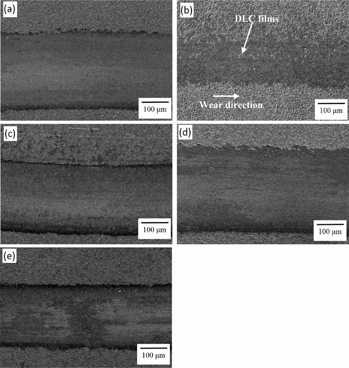
Figure 5 shows the SEM surface morphology observations of the wear tests (axial load of 2 N, and sliding speed of 0.25 m·s−1) under the different power densities of DC-pulsed PECVD. As Figs. 5(a)–5(e) show, none of the specimens generated a large amount of spalling between the DLC films and the PM60 substrate. Also, a significant narrow wear track was evident in the 400 mW·cm−2 specimen. As determined by the EDS analysis, the 400 mW·cm−2 specimen still retained the clear DLC films (marked by arrows) after the wear tests, as shown in Fig. 5(b). Significantly, the 400 mW·cm−2 specimen possessed the best wear resistance, making the coating less liable to peel off. The 400 mW·cm−2 specimen which had more sp3 bonding and a stable DLC structure thus had good adhesion strength and wear resistance. Meanwhile, the specimens of the lower (200 mW·cm−2) and higher power densities (600, 800 and 1000 mW·cm−2) presented relatively poor wear resistance, as shown in Figs. 5(a) and 5(c)–5(e), having relatively deep and wide wear tracks after the wear tests. Furthermore, there was more debris to be stacked outside the wear track, as shown in Fig. 5(e). Little spalling phenomenon was generated between the DLC/oxynitriding films and the PM60 substrate.
When the axial load of the wear test was increased to 5 N, the wear tracks were obviously deeper and wider, as shown in Fig. 6. Moreover, the wear trend was similar for an axial load of 2 N (as shown in Fig. 5). Figure 6 shows the SEM surface morphology observations of the wear tests (axial load of 5 N, and sliding speed of 0.25 m·s−1) for the different power densities of the DC-pulsed PECVD. The lower power density of the 200 mW·cm−2 specimens resulted in the lower ion energy. Since the gas ion collisions were less intense and the deposition efficiency was lower, the quality of the resulting DLC films was poorer. Hence, the mechanical strength was insufficient and cracks were more easily extended. The DLC films generated obvious micro-cracks which extended outward, as shown in Fig. 6(a). When the power density was increased to 400 mW·cm−2, the appropriate ion collisions and deposition resulted in insignificant cracks appearing on the specimen. The DLC films retained good adhesion strength and a stable structure after the wear tests, as shown in Fig. 6(b). Generally, high ion energy easily causes the collisions to be more intense under the plasma atmosphere, and the DLC structure will have a low content of sp3 carbon and a low hydrogen content. When the power density was increased to 1000 mW·cm−2, the specimen possessed more ion energy and, as a result, the sp3 was easily transformed to sp2, thus increasing the surface defects which led to an unstable DLC structure. Therefore, the DLC films produced more obvious cracks and a spalling phenomenon between the DLC/oxynitriding films and the PM60 substrate after the wear tests, as shown in Fig. 6(c). These SEM observations were consistent with our previous experiments (contrast with Figs. 4 and 5).

Figure 7 shows the Tafel slope results of the PM60 specimens for the various power densities of the DC-pulsed PECVD after the 3.5 wt% NaCl corrosion test. In this study, all the different power densities of DC-pulsed PECVD possessed a significant passivation phenomenon after the 3.5 wt% NaCl corrosion test. With the passivation layer having a protective effect, the chemically inert DLC acted as an excellent barrier to the corrosive solutions. From the point of view of corrosion behavior, the samples with a lower current density (Icorr) and higher potential (Ecorr or polarization resistance Rp) evidenced better corrosion resistance.18) Table 1 lists the corrosion test results of the different power densities of the DLC/oxynitriding duplex-treated PM60 high-speed steel, clearly showing that the corrosion characteristic was poorer when the power density increased. The lowest corrosion current (7.24 × 10⁻⁵ A·cm−2) and highest polarization resistance (6.26 × 10² Ω·cm2) of the PM60 specimens appeared in the 200 mW·cm−2 specimen of the DC-pulsed PECVD process. The 400 mW·cm−2 specimen had a higher corrosion current (1.23 × 10⁻⁴ A·cm−2) and a slightly lower polarization resistance (5.54 × 10² Ω·cm2). Conversely, the 1000 mW·cm−2 specimen possessed the highest corrosion current (1.61 × 10⁻⁴ A·cm−2) and the lowest polarization resistance (3.88 × 10² Ω·cm2). It is reasonable to suggest that corrosion resistance is correlated to the specimen’s surface defects and residual stress, with fewer surface defects leading to a decrease in corrosion. In addition, increasing the power density easily enhanced the kinetic energy which, in turn, tended to increase the strain. Normally, increases in power density result in increases in residual stress. Therefore, the 200 mW·cm−2 specimen, having the fewer surface defects and less residual stress, showed the optimal corrosion resistance. Clearly, excellent corrosion resistance results from applying the suitable power density of the DC-pulsed PECVD.

Table 1. Comparison of the corrosion resistance of PM60 specimens by various power densities of DC-pulsed PECVD after 3.5 wt.% NaCl corrosion test.
| Power density (mW·cm−2) | Icorr (×10−4 A·cm−2) | Ecorr (Volts) | Rp (×102 Ω·cm2) |
|---|
| 200 | 0.72 | −1.08 | 6.26 |
| 400 | 1.23 | −1.03 | 5.54 |
| 600 | 1.30 | −1.05 | 4.27 |
| 800 | 1.47 | −1.06 | 4.10 |
| 1000 | 1.61 | −1.08 | 3.88 |
Figure 8 shows the SEM images of the PM60 specimens after the corrosion tests at the various power densities of the DC-pulsed PECVD. Significantly, there was no obvious corrosion for the power densities of 200 and 400 mW·cm−2, with only a slight amount of pitting corrosion observed, as shown in Figs. 8(a) and 8(b). As the power density was increased, the sp3 bonding structure of the DLC easily transformed to sp2 bonding, and resulted in increased surface defects and weakened corrosion resistance. Thus, more pitting corrosion appeared in the higher power density specimens, as shown in Figs. 8(c) and 8(d). Too high ion energy easily generated unstable sp3 bonding. As a result, the 1000 mW·cm−2 specimens had an increased current density and reduced corrosion resistance; the severe corrosion on its surface is shown in Fig. 8(e). Significantly, the 400 mW·cm−2 specimen of the DC-pulsed PECVD possessed the ideal corrosion resistance in a 3.5 wt% NaCl solution: the suitable power density of the DLC/oxynitriding duplex treatment was advantageous for both wear and corrosion resistance.

4. Conclusions
PM60 high-speed steel, successfully nitrided at 550°C for 8 h and oxide-treated at 525°C for 60 min, possessed a well-oxidized layer and crystal properties. The primary structures of the oxynitride layer were Fe3O4, Fe3N (ε phase) and various MC carbides. In addition, the ion bombardment energy rose relative to the increases in power density, which easily made the sp3 convert to sp2 bonds and cause the ID/IG value to increase. The 400 mW·cm−2 specimen possessed the lowest value of ID/IG (2.38) and the greatest offset amount of the G-peak (1540.8 cm−1); therefore, of all the DLC films, it had more stable sp3 bonds and better adhesion.
The lowest wear volumes of 2.36 × 10⁻³ mm3 (load of 2 N) and 5.67 × 10⁻³ mm3 (load of 5 N) appeared for the power density of 400 mW·cm−2. This specimen also possessed a relatively low corrosion current (1.23 × 10⁻⁴ A·cm−2) and high polarization resistance (5.54 × 10² Ω·cm2). Significantly, the power density of 400 mW·cm−2 was the ideal parameter of the DC-pulsed PECVD, and resulted in stable bonding, better properties, good adhesion strength and wear resistance. This study confirmed that the ideal DLC films were effective in improving the tribological and corrosion properties of the DLC/oxynitriding-treated PM60 high-speed steel.
Acknowledgments
This research is supported by the Department of Chemical and Material Engineering Lunghwa University of Science and Technology, and ASSAB STEELS TAIWAN CO., LTD.
References
- 1) S. A. Manaf, A. A. Mahaidin, M. A. Selamat and T. R. Jaafar: Solid State Sci. Technol., 19 (2011), 170.
- 2) P. L. Tso and C. C. Lu: Int. J. Mach. Tool Manu., 39 (1999), 627.
- 3) S. H. Chang, T. P. Tang, K. T. Huang and J. K. Chen: ISIJ Int., 52 (2012), 499.
- 4) S. H. Chang, Y. K. Lin and K. T. Huang: Surf. Coat. Technol., 207 (2012), 571.
- 5) S. H. Chang, T. P. Tang, Y. C. Chen and J. K. Chen: ISIJ Int., 49 (2009), 421.
- 6) M. Ebrahimi, F. Mahboubi and M. R. Naimi-Jamal: Diam. Relat. Mater., 52 (2015), 32.
- 7) Y. Wang, X. Ma, G. Tang and M. Sun: Vacuum, 89 (2013), 74.
- 8) H. Pedersen, P. Larsson, A. Aijaz, J. Jensen and D. Lundin: Surf. Coat. Technol., 206 (2012), 4562.
- 9) A. K. Roy and W. A. Goedel: Surf. Coat. Technol., 205 (2011), 4177.
- 10) M. Noda and M. Umeno: Diam. Relat. Mater., 14 (2005), 1791.
- 11) M. Gunther, I. Bialuch, S. Peter, K. Bewilogua and F. Richter: Surf. Coat. Technol., 205 (2011), S94.
- 12) S. H. Chang, C. I. Lee and K. T. Huang: ISIJ Int., 54 (2014), 193.
- 13) G. Fedosenko, A. Schwabedissen, J. Engemann, E. Braca, L. Valentini and J. M. Kenny: Diam. Relat. Mater., 11 (2002), 1047.
- 14) C. C. Chen and F. C. N. Hong: Appl. Surf. Sci., 243 (2005), 296.
- 15) N. Vidakis, A. Antoniadis and N. Bilalis: J. Mater. Process. Technol., 143–144 (2003), 481.
- 16) N. Kumar, S. A. Barve, S. S. Chopade, R. Kar, N. Chand, S. Dash, A. K. Tyagi and D. S. Patil: Tribol. Int., 84 (2015), 124.
- 17) P. Wang, T. Takeno, J. Fontaine, M. Aono, K. Adachi, H. Miki and T. Takagi: Mater. Chem. Phys., 145 (2014), 434.
- 18) F. R. Marciano, E. C. Almeida, D. A. Lima-Oliveira, E. J. Corat and V. J. Trava-Airoldi: Diam. Relat. Mater., 19 (2010), 537.