Regular Article
Corrosion Behaviour of Alloy 800H in Low Density Superheated Steam
2016 Volume 56 Issue 6 Pages 1067-1075
Details
2016 Volume 56 Issue 6 Pages 1067-1075
The integrity of materials is of great concern in the construction of nuclear reactors. During the design of Gen IV supercritical water reactors, materials characterization under simulated conditions must be carried out to aid proper material selection. In this study, the long term corrosion resistance of Alloy 800H under low pressure superheated steam (SHS) at a temperature of 800°C and 0.1 MPa was tested for up to 3000 hours. The results showed that all six samples experienced weight gain in the first 2000 hours while both weight gain and weight loss were found after 3000 hours. Visual inspection and SEM surface analysis suggest the likelihood of oxide exfoliation at a later stage of the testing in SHS. Additionally, chromia formed on all samples after 1000, 2000 and 3000 hours as well as spinel and hematite.
Exploring long term energy solutions, particularly those employing nuclear energy, has become a subject of global interest in view of the world’s rapid population growth and increased dependence on electricity.1) Built upon Generation II and III nuclear reactor technologies, the Generation IV International Forum was initiated to jointly develop advanced reactor designs.2) The goal in developing Gen IV nuclear reactors is to make improvements in four main categories: sustainability, safety and reliability, economics, and proliferation resistance and physical protection.2) One of six technologies currently being developed is Supercritical Water-Cooled Reactors (SCWR). Single-phase supercritical water (SCW) will be utilized as the coolant in the Gen IV SCWR enabling substantial increase in the thermodynamic efficiency, from 33% of the currently used light water-cooled reactors to 45%.3) The preliminary design of the Canadian SCWR subjects the coolant to an operating pressure of 25 MPa, and a core inlet and outlet temperature of 350°C and 625°C, respectively.4) This design specification requires materials for in-core and out-of-core components that can withstand a wide temperature range (up to 800°C of peak cladding temperature), different pressure values and radiation damage. To date there have been no materials tested under these conditions for extended periods of time.
Ferritic-martensitic (F-M) steels have been considered as a candidate material because of their low cost, low neutron absorption rates, resistance to radiation and swelling upon radiation exposure.5,6,7,8) However, ferritic steels have a low working temperature and exhibit poor mechanical strength above 650°C.9) Unacceptably high levels of corrosion was experienced by F-M steels when being exposed to SCWR conditions.10,11) In an effort to improve upon F-M steels, the development of iron-based oxide dispersion strengthened (ODS) steels is being explored to improve the creep and tensile properties of the material at higher temperatures.12) Ni-based alloys are another candidate for use in the SCWRs due to their ability to maintain high strength and toughness at elevated temperatures. Compared to F-M steels and austenitic stainless steels, Ni-based alloys have superior oxidation and corrosion resistance in SCW and exhibit good creep resistance at high temperatures.9,13) Zhang et al.14) studied various Ni-based alloys and reported a lower corrosion rate when exposed to SCW conditions. However, despite their superiority in oxidation and corrosion resistance Ni-based alloys have high neutron absorption cross sections and greater vulnerability to radiation damage than iron-based alloys, eliminating them as a candidate material for the reactor core.10,15)
Fe-based alloys containing Ni, particularly austenitic stainless steels, are of great interest for use in the Gen IV SCWRs because of their high resistance against creep and radiation as well as improved corrosion resistance over F-M steels.16) Austenitic stainless steels are an attractive choice for in-core and out-of-core components as they are able to maintain their oxidation resistance and mechanical properties up to a temperature of 1000°C in an oxidizing environment.16) There has been concern relating to austenitic stainless steel’s vulnerability to spallation after exposure to harsh conditions,17,18) however, Otaguro et al.18) demonstrated that with the addition of nickel excellent corrosion resistance with a reduced rate of spallation is observed. In a separate study, the Japanese proposed modifying 310 stainless steel with Zr to be used as fuel cladding material and also demonstrated good general corrosion resistance up to 600°C.19)
The current work aims to assess the use of 800H as candidate materials for the Canadian SCWR by exposing the alloy to superheated steam (SHS) at 800°C (0.1 MPa) for 1000, 2000 and 3000 hours. Although the high Ni content, 35% Ni in 800H vs. 20% Ni in 310 stainless, could be a concern in terms of neutron influence, the higher tensile and rupture strength of 800H at 800°C may warrant an investigation into its corrosion behaviour in steam at this elevated temperature.20,21) Furthermore, as there is currently no supercritical test rig available for temperatures near 800°C, a steam rig was constructed and used in this study. It is well recognized by other researchers that the density of SCW has an impact in the corrosion of materials.22,23,24) This impact seemed to have diminished with the rise of temperature as seen in our comparative studies at 625°C where in particular the fluid density has minimal impact on the weight changes of high Cr containing 310 stainless and IN 625 (Fig. 1).25) The results of long term steam testing of 800H are reported in this study.

Weight change measurement for four alloys tested in steam (0.1 MPa), sub-critical (8 MPa) and supercritical (29 MPa) conditions after 1000 hr at 625°C.25)
As a derivate of the original Alloy 800 with controlled carbon content for improved creep strength, 800H is classified as a super-austenitic stainless steel with Ni and Cr content to provide enhanced corrosion resistance (Table 1). The solid-solution strengthened alloy is further strengthened by precipitation of titanium nitrides, titanium carbides and chromium carbides.26) The high strength and corrosion resistance of 800H at elevated temperatures make the alloy a promising candidate material for high temperature conditions such as the reactor cladding guide tube in the SCWR design.5) 800H is approved under the Boiler and Pressure Vessel Code of American Society of Mechanical Engineers (ASME).27) The corrosion rate of 800H, measured by hydrogen evolution rate constant, was found to be about 15 times less than 316 stainless steel in SCW at 750°C.28) Despite its superior properties in harsh conditions, the alloy has demonstrated high risk to oxide exfoliation.29,30) Studies however have showed that reduced oxide spallation of 800H can be achieved successfully by grain boundary engineering31) and shot-peening the surface.26)
| ALLOY | Fe | Ni | Cr | Mn | C | Si | S | AL |
|---|---|---|---|---|---|---|---|---|
| 800H | Bal. | 34.8 | 22.5 | 1.59 | 0.08 | 0.95 | 0.015 | 0.45 |
Six samples of each alloy measuring 10 mm × 15 mm were sheared from a sheet with 1.3 mm thickness. To hang samples in the steam rig, a drill press was used to drill 3.175 mm diameter holes through the samples. Samples were then grinded at 240, 320, 400 and 600 grit using SiC abrasive papers. After grinding, the samples were cleaned in an ultrasonic bath (Branson 2510) using soap and water for 45 minutes followed by 15 minutes in acetone. To remove all moisture, the samples were placed in a furnace (Cole-Parmer Stable Temp) at 200°C for two hours. Sample dimensions (Mitutoya micrometer) and weights were recorded (Mettler Toledo AG285, 10−5 g precision) both before and after testing in SHS to calculate the weight change per unit surface area (Table 2).
| Exposure time (hrs) | 800H-1 | 800H-2 | 800H-3 | 800H-4 | 800H-5 | 800H-6 |
|---|---|---|---|---|---|---|
| 0 | 0 | 0 | 0 | 0 | 0 | 0 |
| ~1000 | 0.163889 | 0.180809 | 0.186990 | 0.225601 | 0.193905 | 0.290710 |
| 2000 | – | 0.468951 | 0.360316 | 0.286145 | 0.256813 | 0.383410 |
| 3000 | – | – | 0.661659 | 0.024506 | 0.878494 | – |
A superheated steam rig was used to simulate SCWR conditions.32) A schematic diagram of the system is shown in Fig. 2. The water distiller supplies the gear pump (Cole-Parmer) with water, which is then pumped into the steam generator (MHI). The steam generator discharges superheated steam into the superheater (MHI) where the superheated steam reaches the final testing temperature. The steam flows into an 18” long 316 stainless steel tube with 1.5” diameter, where the samples are hung on ceramic rods. Exhaust steam from the superheater is discharged to the water reservoir.

Superheated steam rig.
Six 800H samples were tested at 800°C and 0.1 MPa. 800H-1 and 800H-2 samples were removed from the steam rig after 1000 and 2000 hours, respectively. 800H-6 was added to the steam rig after 1000 hours. The remaining three samples of 800H were tested for 3000 hours. Following ~1000, 2000 and 3000 hours of testing, the surface microstructures were characterized using scanning electron microscopy (SEM) and energy dispersive spectrometry (EDS) to examine the progression of oxide formation on the surface. After 3000 hours of exposure to SHS samples were coated with gold for edge retention and conductivity, cross sectioned and characterized using SEM/EDS. Phase composition of the surface oxides formed after 1000, 2000, and 3000 hours were also analyzed using XRD. A Co Kα radiation X-ray source was used with an applied voltage and current of 35 kV and 40 mA, respectively. All tests were carried out within a 2θ range of 25–80° (θ is the angle between the incident X-ray beam and the horizontal surface of the sample).
As shown in Fig. 3(a), after ~1000 hours exposure to SHS, all five sample lost their initial silvery, metallic surface feature and were covered with a uniform brown scale. Further exposure to SHS for 2000 (Fig. 3(b)) and 3000 (Fig. 3(c)) hours resulted in similar surface appearance, all are covered with dark grey scale. On sample surfaces after 2000 and 3000 hours, the surface scale was uneven and contained many depressions, indicating possible oxide spallation/exfoliation.

800H after SHS exposure at (a) ~1000 h, (b) 2000 h and (c) 3000 h.
Figure 4 illustrates the weight change per unit surface area over a total of 3000 hours of exposure to SHS at 800°C and 0.1 MPa. The formation and growth of an oxide layer on the surface causes weight gain while the dissolution or spallation/exfoliation of the oxide layer results in weight loss. All 800H samples demonstrated continuous weight gain after 2000 hours of exposure to SHS indicating continuous formation and growth of surface oxides. Two of three samples exposed to 3000 hours of SHS (800H-3, 4) experienced weight loss following initial weight gain; this result suggests oxide spallation/exfoliation after extended exposure. This is consistent with visual observation where uneven surface scale was observed after 2000 and 3000 hours. While there is an inconsistency in weight change among samples -3, -4 and -5, all exposed to SHS for 3000 hours, it nevertheless indicates the beginning of scale exfoliation. The extent of scale exfoliation may not be uniform and oxides continue to form beneath previously formed oxides as well as on the exposed metal surface following exfoliation.

Weight change of 800H as a function of exposure time in SHS, 800°C, 0.1 MPa.
The following subsections detail SEM and XRD analysis results. The phase identification is primarily based on the EDS compositional results and XRD analysis of samples. Several common oxides formed on stainless steels and elemental weight percentages are provided in Table 3.
| O | Fe | Cr | Ni | |
|---|---|---|---|---|
| NiO | 21.4 | 78.6 | ||
| Fe2O3 | 30.1 | 69.9 | ||
| Fe3O4 | 27.6 | 72.4 | ||
| NiCr2O4 | 28.2 | 45.9 | 25.9 | |
| Ni(FeCr)2O4 | 27.8 | 24.2 | 22.6 | 25.5 |
| Cr2O3 | 31.6 | 68.4 | ||
| (CrFe)2O3 | 30.8 | 35.8 | 33.4 |
After 1000 hours of exposure to SHS at 800°C (0.1 MPa), three distinct surface features were observed on 800H sample surface, each exhibiting different contrast and morphology. The region A (Figs. 5 and 6(a)) is quite smooth and contains mostly O and Fe (Fe2O3 by comparing the results to that shown in Table 3). Region B has small crystals, EDS analysis reveals high content of Ni, Fe, Cr and O (Figs. 5 and 6(b)). From the composition analysis results and XRD analysis of the sample (Fig. 7), it is likely NiO+Cr2O3 or a spinel type oxide (Ni,Mn,Fe)Cr2O4, assuming the crystal structure of NiCr2O4. The third region (C in Figs. 5 and 6(c)) is covered with plate-like crystals, EDS and XRD analyses suggest the presence of either Cr2O3 or (Cr,Fe)2O3 on the surface. The uneven nature of oxidized surface was also observed on 800H tested in SCW at 600°C for 1440 hours.33) A schematic diagram shown in Fig. 15(a) illustrates the oxide on 800H after 1000 hours.

Microstructure of 800H after 1000 hour exposure to SHS at 800°C, 0.1 MPa. (a) SEM image at 500X. (b) EDS analysis results for regions A, B and C.

Microstructure of 800H after 1000 hour exposure to SHS at 800°C, 0.1 MPa. SEM image at 5kX of (a) Region A (b) Region B and (c) Region C.

XRD diffraction pattern of 800H surface after 1000 h hour exposure to SHS at 800°C, 0.1 MPa.
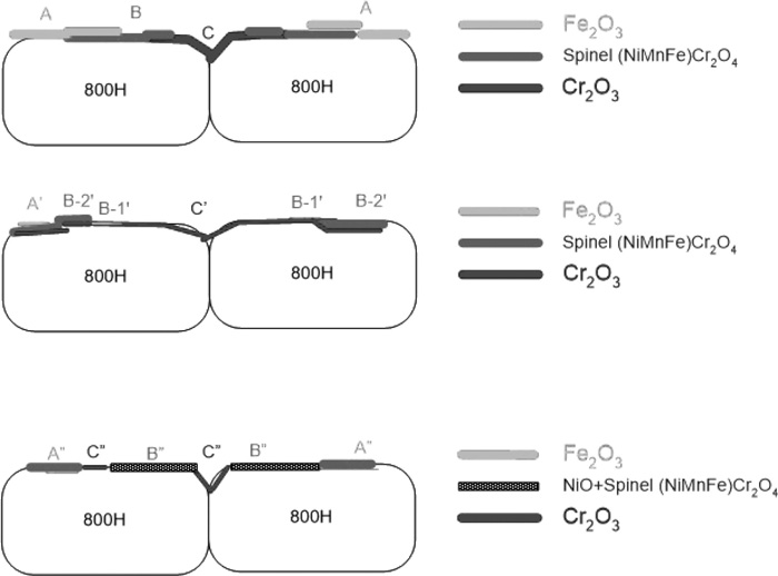
Schematic diagram showing oxide formation progression and exfoliation.
After 2000 hours of exposure to SHS the majority of the surface area was covered with small crystals, measuring 1 to 2 micron in size, as shown in region C’ of Figs. 8(a) and 8(b), suggesting extended Cr-rich oxide coverage. The elevated Cr measured in region C’ as compared to region C in Fig. 5, and XRD analysis result (Fig. 9) further confirm Cr2O3 oxide development in its composition and thickness. The remaining surface has microstructural features A’ and B’ (Fig. 8(a)), similar to A (flat) and B in Fig. 5(a) after 1000 hours. Based on EDS analysis (Fig. 8(c)) and Table 3 smooth area A’ is believed to be primarily Fe2O3 or (Fe,Cr)2O3, the Ni content may have emerged from the spinel oxide layer underneath. Although presence of Fe3O4 was also likely, based on the published literature.26,34,35,36) The amount of Fe2O3 or Fe3O4 on the surface may be too little or too thin to be detected by XRD. The smooth and flat characteristics of region A’ also indicate the site of scale exfoliation, corresponding to that observed on Fig. 3(b). Region B’ can be further divided into B-1’ and B-2’ where B-1’ has Cr, Fe and O (possibly Cr2O3+Fe2O3) and B-2’ contains Cr, Fe, Ni, Mn and O, presumably (Ni,Mn,Fe)Cr2O4 based on the XRD result in Fig. 9. A schematic diagram shown in Fig. 15(b) illustrates the oxide on 800H after 2000 hours. It is to be noted that the X-ray peaks representing austenite phase (the substrate) become more prominent after 2000 hours, when being compared to that after 1000 hrs (see NiFe peaks in Fig. 9 vs. Fig. 7). This suggests thinner or reduced oxide on the surface resulting from initial oxide spallation.

Microstructure of 800H after 2000 hour exposure to SHS at 800°C, 0.1 MPa. (a) and (b) SEM images at 100X and 2kX. (c) EDS analysis results for regions A’, B-1’, B-2’ and C’.

XRD diffraction pattern of 800H surface after 2000 h hour exposure to SHS at 800°C, 0.1 MPa.
Following 3000 hours of testing, about half of the 800H surface contained Cr2O3 crystals, measuring 1 to 5 micron (C” in Figs. 10(a) and 10(c)). A patchy appearance started to show, suggesting further oxide spallation/exfoliation which coincides with the observed weight loss after 3000 hours of exposure to SHS (Fig. 4). EDS confirmed the presence of Cr2O3 in region C” (both C” within the grain in Fig. 10(a) and intergranular C” in (c)) while the patchy region consisting of A” (Fig. 10(a)) and B” (Fig. 10(c)), contained Fe, Ni, Cr, and O (Fe-rich) and Ni, Cr, Fe and O (Ni-rich), respectively (Figs. 10(b) and 10(d)). Region A” may consist of a mixture of Fe2O3 and (Ni,Mn,Fe)Cr2O4 and region B” NiO + (NiFe)Cr2O4. The presence of these phases on the sample surface is identified by XRD analysis (Fig. 11). Based on the XRD results of the surface and EDS, the oxide layer contains (Ni,Mn,Fe)Cr2O4, NiO, Fe2O3, and Cr2O3. The Cr2O3 must be very thin as the X-Ray diffraction intensity was quite weak. The γ-Fe and NiFe detected by XRD are from the bulk material. This also suggests that X-Ray penetrated to the substrate material. The oxide layer was further characterized by examining the cross section where a distinct oxide layer is visible (Fig. 12). The dense oxide layer, measuring 10 to 15 micron in thickness, was observed to adhere to the base alloy across the entire cross-sectional area examined. Six EDS spectra were taken along the length of the oxide layer, all containing predominantly Fe, Ni, Cr and O (Fig. 12(b)).

Microstructure of 800H after 3000 hour exposure to SHS at 800°C, 0.1 MPa. (a) and (c) SEM images at 500X and 2kX. (b) and (d) EDS.

XRD diffraction pattern of 800H surface after 3000 h hour exposure to SHS at 800°C, 0.1 MPa.

Cross section of 800H after 3000 hour exposure to SHS at 800°C, 0.1 MPa. (a) SEM image at 1kX. (b) EDS.
The harsh environment imposed by the SCW and nuclear irradiation presents a challenge in material choice. The lack of knowledge on materials’ performance under extremely high temperatures further compounded the problem. Without the formation of a stable and adherent surface oxide layer deterioration by corrosion and oxidation in the SCWR core is expected. To avoid such circumstances candidate materials for the SCWR should include oxide formers such as chromium, aluminum, silicon, niobium, and tantalum.37) All stainless steels contain chromium as the primary oxide former and have been among some of the material candidates considered for the fabrication of the SCWR.35)
In the current work, alloy 800H was evaluated in steam at 800°C. All samples experienced weight gain in the first 2000 hours, although with some variation in values. The average weight gain (Fig. 13) after 1000 and 2000 hours could not be reasonably compared to the published test results of 800H in SCW due to the differences in test duration, temperature and test pressure. One study of Alloy 800H, however, at SCW temperature of 600°C, saw a similar weight gain of 0.2 mg/cm2 after 1000 hours.35) Samples exposed for 3000 hours displayed both weight gain and weight loss. The weight loss provided indication of oxide scale exfoliation. Similar observations were reported when testing 800H in SCW at 500°C and 25 MPa. An averaged weight gain of ~0.1 mg/cm2 was observed after 600 hours and ~0.03 mg/cm2 after 1000 hours; the weight gain reduction after 1000 hours was attributed to oxide exfoliation by the authors.26) Likewise, the weight change data in the same study were widely scattered at different test durations, for example, after 600 hours, the weight gain fell between 0.09–0.39 mg/cm2. It has been commonly agreed that the weight gain of austenitic steels due to oxidation in SCW is less than F-M steels, however, the measured weight gain/loss is scattered.26,35) Based on the results from this study, 800H also experienced large weight change variations and weight loss, as the test progressed, under high temperature steam environment. Oxide exfoliation is a cause for concern as it has the consequences to hardware blockage, transport of radioactive materials and erosion to turbine rotors.

Averaged weight change of alloy 800H in SHS.
Surface oxide formation on alloy 800H during SHS exposure was very complex, with at least three separate regions containing different microstructure: area A with Fe2O3, area B with spinel (Ni,Mn,Fe)Cr2O4 (or (Ni,Mn,Fe,Cr)3O4 having similar crystal structure to magnetite Fe3O4) and NiO and finally area C with Cr2O3. Cr2O3 was observed to form on all samples after 1000, 2000 and 3000 hours of SHS exposure. The total oxide layer reached 15–20 μm in thickness after 3000 hours in SHS.
In one published study of Alloy 800H in SCW at 500°C and a pressure of 25 MPa, it was found that oxides formed in a three-layer manner, including spinel, magnetite (Fe3O4) and hematite (Fe2O3), from inner to outer layer. This is consistent with thermodynamic calculations where an element forming oxides with different states will have the oxide with higher state (such as Fe2O3) situated on top of the lower state oxide (Fe3O4), instead of forming a mixture of both.36) Exfoliation was observed between the interfaces of spinel-magnetite and magnetite and hematite, due to thermal expansion mismatch.26) Another study found oxide formed in 500°C SCW consisted of magnetite/spinel adjacent to the substrate and an external layer of hematite (Fe2O3).34) At higher SCW temperature of 600°C, magnetite outer oxide layer and spinel (Ni,Mn,Fe,Cr)3O4 inner oxide layer were found after 1000 hours.35) Other study found an inner oxide layer of FeCrO3 and outer layer of NiFe2O4 after 1440 hours in SCW at 600°C.33) No Cr2O3 was reported on 800H after SCW testing at temperature from 500 to 600°C. One of the few studies carried out in high temperature steam reported that for stainless steels with 20–22 wt.% Cr, a duplex oxide structure, including inner layer Cr2O3 could be formed at 700°C after 1000 hours (Fig. 14).38)

Schematic representation of oxide scale on austenitic stainless steels tested in steam [44].
Comparing the oxide formation on Alloy 800H after SCW exposure and that from this study, both similarities and differences are found. Spinel or magnetite formation were observed in all studies, irrespective of temperature and pressure. However, hematite was found in some studies but not in others. This is likely a result of hematite exfoliation and the differences in oxidative nature of the test medium (SCW or steam) and other dynamic factors. In fact, thermodynamic prediction based on alloy composition and 500°C steam condition suggests formation of spinel (Fe, Cr, Ni, Mn)3O4 in the outer layer.39) Finally, Cr2O3 was observed on all 800H samples after 1000, 2000 and 3000 of testing in SHS; this was not reported in several studies of 800H in SCW. Temperature may have played a role.
The following diagram (Fig. 15) summarizes the oxide formation and spallation during the current SHS test. Note that the layered structure is speculated based on literature and EDS/XRD results of mixed oxides. After 1000 hours, Cr2O3 formation developed around the grain boundary region along with other oxides such as hematite Fe2O3 and spinel (Ni,Mn,Fe)Cr2O4 (Fig. 15(a)). As the SHS exposure progressed (to 2000 hours), more Cr2O3 formed between the substrate and outside scale and spallation of Fe2O3 began to occur (Fig. 15(b)). The remaining small amount of Fe2O3 was present mostly atop spinel or chromia. At this stage, the oxide is considered thin and protective. Further SHS exposure, up to 3000 hours, resulted in Cr-depletion and as such Fe2O3 and NiO formation started to take place. The remaining Cr in the substrate continued to be oxidized and was mostly incorporated into the spinel phase (Fig. 15(c)).
Lastly, due to the lack of facility capable of SCW corrosion testing at 800°C, the validity of substituting SCW with low pressure steam is uncertain. It has been suggested that the higher pressure of SCW creates higher density corrosion medium, which in turn can vary the corrosion kinetics by (1) changing the dissolution of ions in SCW or steam and accelerating the corrosion rate and (2) enhancing the number of oxidizing species on the oxide surface.40) Experimental study of several ferritic - martensitic steels at 500°C concluded that equivalent or low mass gain (i.e. oxide thickness) was resulted in steam than that in SCW at 500°C.41) However, the first factor becomes less significant with increasing temperature where it has a less significant effect on water density.40)
The current study investigated the long term corrosion resistance of 800H under simulated SCWR condition using SHS at a temperature of 800°C (0.1 MPa) from 1000 to 3000 hours. All samples experienced weight gain in the first 2000 hours while both weight gain and weight loss were observed after 3000 hours, an indication of oxide exfoliation. Visual inspection and SEM surface analysis confirmed the likelihood of oxide exfoliation. In terms of surface oxide formation, Cr2O3 was observed on all samples after 1000, 2000 and 3000 hours. In addition, spinel and hematite were also present. Further TEM and XRD analysis with grazing-incidence mode (nm scale) will be carried out to examine the layered oxide structure.
Funding to this research was provided by Natural Resources Canada through the Office of Energy Research and Development, Atomic Energy of Canada Limited, and Natural Sciences and Engineering Research Council of Canada under the Canada Gen-IV National Program. We also thank Mr. F. Barrett and Mr. R. Sanchez for setting up the steam rig and weighing the samples.