Abstract
Based on the ion and molecule coexistence theory (IMCT) and slag-metal equilibrium theory, a thermodynamic model to design the slag compositions balanced with the consumable electrode of G20CrNi2Mo bearing steel during electroslag remelting (ESR) process was developed. With this model, an equilibrium slag system of Al2O3, SiO2, MnO and FeO can be obtained quantitatively, which is favorable to decrease the extent of steel constituents oxidized by the molten slag. In order to validate the reasonability of this model, an industrial experimental with four types of slag systems was carried out in a special steel plant of China. The composition variation of Al, Si, Mn and oxygen corresponds well with deviation of Al2O3, SiO2, MnO and FeO from equilibrium, reflecting the reasonability of this model. This model could also provide some guidance for deoxidation practice during industrial ESR process. It is concluded that large deviation of measured FeO from equilibrium is a key factor leading to the Al-oxidation and oxygen increase. In order to improve the cleanliness of refined ingot, under the premise of one slag system with relatively low CaO content, a feasible means is to strengthen the protecting atmosphere or add strong oxidizer into the slag pool to suppress the FeO-activity to a minimum level, particularly during the last stage of remelting.
1. Introduction
As the demand for the high-performance steel continues to rise, the electroslag remelting (ESR) process has become increasingly significant because of its advantages such as the removal of large dimension inclusions, structure of directionally solidified, smooth ingot surface,1,2,3) etc. However, precise control of the homogeneity of refined ingot becomes considerably difficult due to the long-time contact between slag and metal interfaces. Coupled reactions will occur at the slag-metal interfaces simultaneously so that oxidation of the easily oxidized elements in the consumable electrode such as Al, Si, Ti and Mn cannot be avoided. Therefore, it is desirable to develop a means to decrease the degree of slag-metal reactions in order to improve the homogeneity of the ingot, particularly when remelting the steel with a narrow composition range.
During the past a few decades, several researchers have focused more on the change mechanism of ingot composition based on the slag-metal reactions qualitatively, such as Fraser et al.,4) Allibert et al.,5) Mitchell et al.,6) Carmona et al.,7) S. F. Medina et al.8,9,10) In addition, Chai et al.,11,12) have developed a thermodynamic model of equilibria existing between the slag and metal during submerged arc welding, which provided a means of calculating the steel composition balanced with a flux of known composition. However, it is still remained unknown about how to design an equilibrium slag system quantitatively according to the initial composition of steel.
It is generally accepted that although a complete thermodynamic equilibrium may be not achieved during the industrial ESR process, the kinetics is so favorable that a state close to equilibrium can be reached during the quasi-state remelting stage.13) There are three reaction sites during the ESR process, electrode tip-slag interface, droplet-slag interface, metal pool-slag interface, respectively,14) but it has been confirmed that the interface between electrode tip and slag is the most important site for chemical reactions due to the large surface area and relatively low temperature.15,16,17) Therefore, it is reasonable to design the slag system balanced with the consumable electrode at the electrode tip-slag interface from thermodynamics in order to improve the homogeneity of ingot in the longitudinal direction. In the present study, a thermodynamic model was established based on the ion and molecule coexistence theory (IMCT)18) and slag-metal equilibrium theory. With the equilibrium slag system, the degree of slag-metal reactions will be controlled to a low extent. In order to validate the accuracy of this model, an industrial experimental was carried out in a special steel plant of China. In addition, this model can also provide some guidance for deoxidation practice during industrial ESR process.
2. Description of Model
2.1. Model Assumptions
(1) The primary reactions of interest include oxygen, Al, Si, and Mn. It is considered that a thermodynamic equilibrium at the electrode tip-slag interface does exist between Al+Al2O3, Si+SiO2, Mn+MnO and Fe+FeO system.
(2) The slag system used during ESR process is usually composed of seven components: CaF2, CaO, Al2O3, MgO, SiO2, MnO and FeO. According to IMCT, the structural units in the CaF2-containing slag are composed of simple ions Ca2+, Mg2+, Mn2+, Fe2+, F− and O2−, simple molecules Al2O3, SiO2, and complex molecules such as 11CaO·7Al2O3·CaF2, aluminates and silicates.
(3) In the slag, a dynamic equilibrium occurs between simple ion and molecule by taking Ca2+, O2− and Al2O3 forming CaO·2Al2O3 as an example (Ca2++O2−)+2Al2O3=CaO·2Al2O3.
(4) In the slag, the process forming the complex molecule compounds complies with the law of mass conservation. Therefore, the equilibrium constants of various chemical reactions could be presented as a function of mass action concentration.
2.2. Establishment of Model
2.2.1. Schematic Diagram of the Model
The objective of this model is to obtain the equilibrium slag system according to the composition of consumable electrode. The schematic diagram of the thermodynamic model is shown in Fig. 1. The interface between the electrode tip and slag is considered as the main reaction area, and all the reactions reach equilibrium state simultaneously.
In this paper, only the equilibrium compositions of Al2O3, SiO2, MnO and FeO during the remelting process are taken into consideration. The contents of CaF2, CaO and MgO are considered as known values for the following reasons:
(1) No component in the molten steel is to be balanced with CaF2 which is mainly taken as the conductive solvent.
(2) The dissolved contents of Ca and Mg are remained unknown in the molten steel. The measured values in the ingot are the content of total Ca and Mg, much higher than the dissolved value in the molten steel.
2.2.2. Expressions of Slag-Metal Reactions
The related reactions take place at the electrode tip-slag interface simultaneously, as given in Eqs. (1), (2), (3), (4):
|
2[Al]+3[O]=(A
l
2
O
3
)
| (1) |
The expressions of standard equilibrium constants of Eqs. (1), (2), (3), (4) are shown in Eqs. (5), (6), (7), (8):
|
lgK
1
θ
=lg
a
Al
2
O
3
a
2
Al
⋅
a
3
O
=lg
a
Al
2
O
3
f
2
Al
[wt%Al]
2
f
3
O
[wt%O]
3
=64 000/T-
20.57
| (5) 19) |
|
lgK
2
θ
=lg
a
SiO
2
a
Si
⋅
a
2
O
=lg
a
SiO
2
f
Si
[wt%Si]
f
2
O
[wt%O]
2
=30 410/T-
11.59
| (6) 20) |
|
lgK
3
θ
=lg
a
MnO
a
Mn
⋅
a
O
=lg
a
MnO
f
Mn
[wt%Mn]
f
O
[wt%O]
=15 015/T-
6.664
| (7) 19,21) |
|
lgK
4
θ
=lg
a
FeO
a
O
=lg
a
FeO
f
O
[wt% O]
=6 320/T-
2.734
| (8) 22) |
Where aMxOy is the activity of the component in the slag, fi is the activity coefficient of the component in the steel, which can be calculated by Wagner Equation, as shown in Eq. (9):
|
lg
f
i
=∑
e
i
j
[wt% j]
| (9) |
The first-order interaction coefficients
e
i
j
of constituents in molten steel are listed in Table 1.
Table 1. First-order interaction coefficients
e
i
j
of constituents in molten steel.
23)| i \ j | C | Si | Mn | S | Al | Cr | O |
|---|
| Al | 0.091 | 0.056 | | 0.030 | 63/T+0.011 | 0.01224) | −34740/T+11.95 |
| Si | 380/T−0.023 | 34.5/T+0.089 | 0.002 | 0.056 | 0.058 | −0.0003 | −0.23 |
| Mn | −0.07 | | | −0.048 | | 0.0039 | −0.083 |
| O | −0.43625) | −0.131 | −0.021 | −0.133 | −20600/T+7.15 | −0.045924) | −1750/T+0.734 |
Equations (10), (11), (12), (13) could be derived from Eqs. (5), (6), (7), (8):
|
2lg[wt%Al]+2lg
f
Al
+3lg[wt%O]+3lg
f
O
=lg
a
Al
2
O
3
-lg
K
1
θ
| (10) |
|
lg[wt%Si]+lg
f
Si
+2lg[wt%O]+2lg
f
O
=lg
a
Si
O
2
-lg
K
2
θ
| (11) |
|
lg[wt%Mn]+lg
f
Mn
+lg[wt%O]+lg
f
O
=lg
a
MnO
-lg
K
3
θ
| (12) |
|
lg[wt%O]+lg
f
O
=lg
a
FeO
-lg
K
4
θ
| (13) |
As can be seen from Eqs. (10), (11), (12), (13), based on the given contents of Al, Si and Mn, there are five unknowns which are [wt%O], aAl2O3, aSiO2, aMnO, aFeO, respectively, but there are only four equations. Therefore, another equation is needed. With the mass conservation law of IMCT, the five unknowns could be solved.
2.2.3. Calculation of the Equilibrium Slag Compositions
The mole number of each component in 100 g CaF2-containing slag is defined as b1=ΣnCaO, b2=ΣnFeO, b3=ΣnCaF2, b4=ΣnMgO, b5=ΣnMnO, a1=ΣnAl2O3, a2=ΣnSiO2.
The mass action concentration of each component in the slag is represented as follows:
N1=NCaO, N2=NFeO, N3=NCaF2, N4=NAl2O3, N5=NSiO2, N6=NMgO, N7=NMnO
According to IMCT, the mass action concentration of every structural unit is defined as a ratio of equilibrium mole number to the total mole numbers of all structural units, which can be calculated by Eq. (14):
Where ni is the equilibrium mole number of each structural unit, Σni is the total numbers of all components in the slag. The nature of mass action concentration Ni is the equilibrium mole fraction of structural unit i, very consistent with Raoult activity in which the pure solid as the standard state. The difference between the two types of activity mainly lies in that mass action concentration Ni avoids activity coefficient of Raoult activity effectively. Several scholars have proved the accuracy of mass action concentration calculated by IMCT, which corresponds well with the measured activities of slag components, such as CaO–Al2O3–SiO2 slags,26) CaO–SiO2–Al2O3–MgO slags,27) CaO–SiO2–MgO–FeO–MnO–Al2O3 slags.28) Therefore, the value of mass action concentration of each unit calculated by IMCT is supposed to be reliable.
It should be noted that the free Me2+ and O2− keep independent form each other, cannot forming MeO whether in liquid or solid state. Therefore, the mass action concentration of MeO is calculated by Eq. (15):
|
N
MeO
=
N
Me
2+
,MeO
+
N
O
2-
,MeO
=
n
Me
2+
,MeO
+
n
O
2-
,MeO
∑
n
i
=
2
n
MeO
∑
n
i
| (15) |
According to the reported phase diagrams CaF2–CaO–Al2O3,29) CaO–SiO2–Al2O3–MgO,30) Al2O3–SiO2–FeOx,30) CaO–MnO–SiO2,31) CaF2–CaO–SiO2,32) twenty-six kinds of complex molecules can be formed in CaF2–CaO–Al2O3–MgO–SiO2–MnO–FeO slag system, plus the seven simple components, up to thirty-three components in the slag. Table 2 shows the structural units, mole number and expressions of mass action concentrations.
Table 2. The structural units, mole number and expressions of mass action concentrations.
| Structural units | Number | Mole number of structural unit | Mass action concentration |
|---|
| Ca2++O2− | 1 |
n
1
=
n
Ca
2+
=
n
O
2-
|
N
1
=2
n
1
/∑
n
i
=
N
CaO
|
| Fe2++O2− | 2 |
n
2
=
n
Fe
2+
=
n
O
2-
|
N
2
=2
n
2
/∑
n
i
=
N
FeO
|
| Ca2++2F2− | 3 |
n
3
=
n
Ca
2+
=2
n
F
-
|
N
3
=3
n
3
/∑
n
i
=
N
CaF
2
|
| Mg2++O2− | 6 |
n
6
=
n
M
g
2+
=
n
O
2-
|
N
6
=2
n
6
/∑
n
i
=
N
MgO
|
| Mn2++ O2− | 7 |
n
7
=
n
Mn
2+
=
n
O
2-
|
N
7
=2
n
7
/∑
n
i
=
N
MnO
|
| Al2O3 | 4 |
n
4
=
n
Al
2
O
3
|
N
4
=
n
4
/∑
n
i
=
N
Al
2
O
3
|
| SiO2 | 5 |
n
5
=
n
SiO
2
|
N
5
=
n
5
/∑
n
i
=
N
SiO
2
|
| CaO·SiO2 | 8 |
n
8
=
n
CaO⋅
SiO
2
|
N
8
=
n
8
/∑
n
i
=
N
CaO⋅
SiO
2
|
| 2CaO·SiO2 | 9 |
n
9
=
n
2CaO⋅
SiO
2
|
N
9
=
n
9
/∑
n
i
=
N
2CaO⋅
SiO
2
|
| 3CaO·SiO2 | 10 |
n
10
=
n
3CaO⋅
SiO
2
|
N
10
=
n
10
/∑
n
i
=
N
3CaO⋅
SiO
2
|
| CaO·Al2O3 | 11 |
n
11
=
n
CaO⋅
Al
2
O
3
|
N
11
=
n
11
/∑
n
i
=
N
CaO⋅
Al
2
O
3
|
| CaO·2Al2O3 | 12 |
n
12
=
n
CaO⋅2
Al
2
O
3
|
N
12
=
n
12
/∑
n
i
=
N
CaO⋅2
Al
2
O
3
|
| CaO·6Al2O3 | 13 |
n
13
=
n
CaO⋅6
Al
2
O
3
|
N
13
=
n
13
/∑
n
i
=
N
CaO⋅6
Al
2
O
3
|
| 3CaO·Al2O3 | 14 |
n
14
=
n
3CaO⋅
Al
2
O
3
|
N
14
=
n
14
/∑
n
i
=
N
3CaO⋅
Al
2
O
3
|
| 12CaO·7Al2O3 | 15 |
n
15
=
n
12CaO⋅7
Al
2
O
3
|
N
15
=
n
15
/∑
n
i
=
N
12CaO⋅7
Al
2
O
3
|
| MgO·SiO2 | 16 |
n
16
=
n
MgO⋅
SiO
2
|
N
16
=
n
16
/∑
n
i
=
N
MgO⋅
SiO
2
|
| 2MgO·SiO2 | 17 |
n
17
=
n
2MgO⋅
SiO
2
|
N
17
=
n
17
/∑
n
i
=
N
2MgO⋅
SiO
2
|
| MgO·Al2O3 | 18 |
n
18
=
n
MgO⋅
Al
2
O
3
|
N
18
=
n
18
/∑
n
i
=
N
MgO⋅
Al
2
O
3
|
| MnO·SiO2 | 19 |
n
19
=
n
MnO⋅
SiO
2
|
N
19
=
n
19
/∑
n
i
=
N
MnO⋅
SiO
2
|
| 2MnO·SiO2 | 20 |
n
20
=
n
2MnO⋅
SiO
2
|
N
20
=
n
20
/∑
n
i
=
N
2MnO⋅
SiO
2
|
| MnO·Al2O3 | 21 |
n
21
=
n
MnO⋅
Al
2
O
3
|
N
21
=
n
21
/∑
n
i
=
N
MnO⋅
Al
2
O
3
|
| 2FeO·SiO2 | 22 |
n
22
=
n
2FeO⋅
SiO
2
|
N
22
=
n
22
/∑
n
i
=
N
2FeO⋅
SiO
2
|
| FeO·Al2O3 | 23 |
n
23
=
n
FeO⋅
Al
2
O
3
|
N
23
=
n
23
/∑
n
i
=
N
FeO⋅
Al
2
O
3
|
| CaO·MgO·SiO2 | 24 |
n
24
=
n
CaO⋅MgO⋅
SiO
2
|
N
24
=
n
24
/∑
n
i
=
N
CaO⋅MgO⋅
SiO
2
|
| CaO·MgO·2SiO2 | 25 |
n
24
=
n
CaO⋅MgO⋅2
SiO
2
|
N
25
=
n
25
/∑
n
i
=
N
CaO⋅MgO⋅2
SiO
2
|
| 2CaO·MgO·2SiO2 | 26 |
n
26
=
n
2CaO⋅MgO⋅2
SiO
2
|
N
26
=
n
26
/∑
n
i
=
N
2CaO⋅MgO⋅2
SiO
2
|
| 3CaO·MgO·2SiO2 | 27 |
n
27
=
n
3CaO⋅MgO⋅2
SiO
2
|
N
27
=
n
27
/∑
n
i
=
N
3CaO⋅MgO⋅2
SiO
2
|
| 2CaO·Al2O3·SiO2 | 28 |
n
28
=
n
2CaO⋅
Al
2
O
3
⋅
SiO
2
|
N
28
=
n
28
/∑
n
i
=
N
2CaO⋅
Al
2
O
3
⋅
SiO
2
|
| CaO·Al2O3·2SiO2 | 29 |
n
29
=
n
CaO⋅
Al
2
O
3
⋅2
SiO
2
|
N
29
=
n
29
/∑
n
i
=
N
CaO⋅
Al
2
O
3
⋅2
SiO
2
|
| 3Al2O3·2SiO2 | 30 |
n
30
=
n
3
Al
2
O
3
⋅2
SiO
2
|
N
30
=
n
30
/∑
n
i
=
N
3
Al
2
O
3
⋅2
SiO
2
|
| 3CaO·2SiO2·CaF2 | 31 |
n
31
=
n
3CaO⋅2
SiO
2
⋅
CaF
2
|
N
31
=
n
31
/∑
n
i
=
N
3CaO⋅2
SiO
2
⋅
CaF
2
|
| 3CaO·3Al2O3·CaF2 | 32 |
n
32
=
n
3CaO⋅3
Al
2
O
3
⋅
CaF
2
|
N
32
=
n
32
/∑
n
i
=
N
3CaO⋅3
Al
2
O
3
⋅
CaF
2
|
| 11CaO·7Al2O3·CaF2 | 33 |
n
33
=
n
11CaO⋅7
Al
2
O
3
⋅
CaF
2
|
N
33
=
n
33
/∑
n
i
=
N
11CaO⋅7
Al
2
O
3
⋅
CaF
2
|
The chemical reaction formulas forming the complex molecules, their standard Gibbs energy as a function of temperature and expressions of mass action concentrations as a function of N1 = (NCaO), N2 = (NFeO), N3 = (NCaF2), N4 = (NAl2O3), N5 = (NSiO2), N6 = (NMgO), N7 = (NMnO) are listed in Table 3.
Table 3. The chemical reaction formulas, their standard Gibbs energy ΔG
θ and expressions of mass action concentrations in CaF
2–CaO–Al
2O
3–MgO–SiO
2–MnO–FeO slags.
| Chemical reactions | ΔGθ (J/mol) | Expressions of mass action concentration |
|---|
| (Ca2++O2−)+SiO2=CaO·SiO2 | −22476–38.52T18) | N8=k1·N1·N5 |
| 2(Ca2++O2−)+SiO2=2CaO·SiO2 | −100986–24.03T18) |
N
9
=
k
2
⋅
N
1
2
⋅
N
5
|
| 3(Ca2++O2−)+SiO2=3CaO·SiO2 | −93366–23.03T18) |
N
10
=
k
3
⋅
N
1
3
⋅
N
5
|
| (Ca2++O2−)+Al2O3=CaO·Al2O3 | −18120−18.62T33) | N11=k4·N1·N4 |
| (Ca2++O2−)+2Al2O3=CaO·2Al2O3 | −16400−26.80T33) |
N
12
=
k
5
⋅
N
1
⋅
N
4
2
|
| (Ca2++O2−)+6Al2O3=CaO·6Al2O3 | −17430−37.20T33) |
N
13
=
k
6
⋅
N
1
⋅
N
4
6
|
| 3(Ca2++O2−)+Al2O3=3CaO·Al2O3 | −17000−32.0T33) |
N
14
=
k
7
⋅
N
1
3
⋅
N
4
|
| 12(Ca2++O2−)+7Al2O3=12CaO·7Al2O3 | −86100−205.1T33) |
N
15
=
k
8
⋅
N
1
12
⋅
N
4
7
|
| (Mg2++O2−)+SiO2=MgO·SiO2 | 43400−40.0T34) | N16=k9·N5·N6 |
| 2(Mg2++O2−)+SiO2=2MgO·SiO2 | −77403+11.0T34) |
N
17
=
k
10
⋅
N
5
⋅
N
6
2
|
| (Mg2++O2−)+Al2O3=MgO·Al2O3 | −35530−2.09T35) | N18=k11·N4·N6 |
| (Mn2++O2−)+SiO2=MnO·SiO2 | −30013−5.02T36) | N19=k12·N5·N7 |
| 2(Mn2++O2−)+SiO2=2MnO·SiO2 | −86670+16.81T36) |
N
20
=
k
13
⋅
N
5
⋅
N
7
2
|
| (Mn2++O2−)+Al2O3=MnO·Al2O3 | −45116+11.81T37) | N21=k14·N4·N7 |
| 2(Fe2++O2−)+SiO2=2FeO·SiO2 | −28596+3.349T38) |
N
22
=
k
15
⋅
N
2
2
⋅
N
5
|
| (Fe2++O2−)+Al2O3=FeO·Al2O3 | −33272.8+6.1028T39) | N23=k16·N2·N4 |
| (Ca2++O2−)+(Mg2++O2−)+SiO2=CaO·MgO·SiO2 | −124766.6+3.768T40) | N24=k17·N1·N5·N6 |
| (Ca2++O2−)+(Mg2++O2−)+2SiO2=CaO·MgO·2SiO2 | −80387−51.916T41) |
N
25
=
k
18
⋅
N
1
⋅
N
5
2
⋅
N
6
|
| 2(Ca2++O2−)+(Mg2++O2−)+2SiO2=2CaO·MgO·2SiO2 | −73688−63.639T41) |
N
26
=
k
19
⋅
N
1
2
⋅
N
5
2
⋅
N
6
|
| 3(Ca2++O2−)+(Mg2++O2−)+2SiO2=3CaO·MgO·2SiO2 | −315469+24.786T18) |
N
27
=
k
20
⋅
N
1
3
⋅
N
5
2
⋅
N
6
|
| 2(Ca2++O2−)+Al2O3+SiO2=2CaO·Al2O3·SiO2 | −61964.64−60.29T41) |
N
28
=
k
21
⋅
N
1
2
⋅
N
4
⋅
N
5
|
| (Ca2++O2−)+Al2O3+2SiO2=CaO·Al2O3·2SiO2 | −13816.44−55.27T41) |
N
29
=
k
22
⋅
N
1
⋅
N
4
⋅
N
5
2
|
| 3(Al2O3)+2SiO2=3Al2O3·2SiO2 | −4354.27−10.47T41) |
N
30
=
k
23
⋅
N
4
3
⋅
N
5
2
|
| 3(Ca2++O2−)+2SiO2+(Ca2++2F−)=3CaO·2SiO2·CaF2 | −255180−8.20T42) |
N
31
=
k
24
⋅
N
1
3
⋅
N
3
⋅
N
5
2
|
| 3(Ca2++O2−)+3Al2O3+(Ca2++2F−)=3CaO·3Al2O3·CaF2 | −44492−73.15T43) |
N
32
=
k
25
⋅
N
1
3
⋅
N
3
⋅
N
4
3
|
| 11(Ca2++O2−)+7Al2O3+(Ca2++2F−)=11CaO·7Al2O3·CaF2 | −228760−155.8T43) |
N
33
=
k
26
⋅
N
1
11
⋅
N
3
⋅
N
4
7
|
According to IMCT, the sum of mass action concentrations of all structural units under equilibrium condition is equal to 1.0, as can be expressed as Eq. (16):
|
N
1
+
N
2
+
N
3
+⋅⋅⋅+
N
32
+
N
33
=
N
1
+
N
2
+
N
3
+⋅⋅⋅
+
k
25
⋅
N
1
3
⋅
N
3
⋅
N
4
3
+
k
26
⋅
N
1
11
⋅
N
3
⋅
N
4
7
=
∑
i=1
33
N
i
=1
| (16) |
According to the law of mass conservation, the mole number of seven components in the slag could be given by Eqs. (17), (18), (19), (20), (21), (22), (23):
|
b
1
=∑n(0.5
N
1
+
N
8
+2
N
9
+3
N
10
+
N
11
+
N
12
+
N
13
+3
N
14
+12
N
15
+
N
24
+
N
25
+2
N
26
+3
N
27
+2
N
28
+
N
29
+3
N
31
+3
N
32
+11
N
33
)
=∑n(0.5
N
1
+
k
1
⋅
N
1
⋅
N
5
+2
k
2
⋅
N
1
2
⋅
N
5
+3
k
3
⋅
N
1
3
⋅
N
5
+
k
4
⋅
N
1
⋅
N
4
+
k
5
⋅
N
1
⋅
N
4
2
+
k
6
⋅
N
1
⋅
N
4
6
+3
k
7
⋅
N
1
3
⋅
N
4
+12
k
8
⋅
N
1
12
⋅
N
4
7
+
k
17
⋅
N
1
⋅
N
5
⋅
N
6
+
k
18
⋅
N
1
⋅
N
5
2
⋅
N
6
+2
k
19
⋅
N
1
2
⋅
N
5
2
⋅
N
6
+3
k
20
⋅
N
1
3
⋅
N
5
2
⋅
N
6
+2
k
21
⋅
N
1
2
⋅
N
4
⋅
N
5
+
k
22
⋅
N
1
⋅
N
4
⋅
N
5
2
+3
k
24
⋅
N
1
3
⋅
N
3
⋅
N
5
2
+3
k
25
⋅
N
1
3
⋅
N
3
⋅
N
4
3
+11
k
26
⋅
N
1
11
⋅
N
3
⋅
N
4
7
)=
n
CaO
| (17) |
|
b
2
=∑n(0.5
N
2
+2
N
22
+
N
23
)
=∑n(0.5
N
2
+2
k
15
⋅
N
2
2
⋅
N
5
+
k
16
⋅
N
2
⋅
N
4
)=
n
FeO
| (18) |
|
b
3
=∑n(1/3
N
3
+
N
31
+
N
32
+
N
33
)
=∑n(1/3
N
3
+
k
24
⋅
N
1
3
⋅
N
3
⋅
N
5
2
+
k
25
⋅
N
1
3
⋅
N
3
⋅
N
4
3
+
k
26
⋅
N
1
11
⋅
N
3
⋅
N
4
7
)=
n
CaF
2
| (19) |
|
b
4
=∑n(1/2
N
6
+
N
16
+2
N
17
+
N
18
+
N
24
+
N
25
+
N
26
+
N
27
)
=∑n(1/2
N
6
+
k
9
⋅
N
5
⋅
N
6
+2
k
10
⋅
N
5
⋅
N
6
2
+
k
11
⋅
N
4
⋅
N
6
+
k
17
⋅
N
1
⋅
N
5
⋅
N
6
+
k
18
⋅
N
1
⋅
N
5
2
⋅
N
6
+
k
19
⋅
N
1
2
⋅
N
5
2
⋅
N
6
+
k
20
⋅
N
1
3
⋅
N
5
2
⋅
N
6
)=
n
MgO
| (20) |
|
b
5
=∑n(1/2
N
7
+
N
19
+
N
20
+
N
21
)
=∑n(1/2
N
7
+
k
12
⋅
N
5
⋅
N
7
+
k
13
⋅
N
5
⋅
N
7
2
+
k
14
⋅
N
4
⋅
N
7
)
=
n
MnO
| (21) |
|
a
1
=∑n(
N
4
+
N
11
+2
N
12
+6
N
13
+
N
14
+7
N
15
+
N
18
+
N
21
+
N
23
+
N
28
+
N
29
+3
N
30
+3
N
32
+7
N
33
)
=∑n(
N
4
+
k
4
⋅
N
1
⋅
N
4
+2
k
5
⋅
N
1
⋅
N
4
2
+6
k
6
⋅
N
1
⋅
N
4
6
+
k
7
⋅
N
1
3
⋅
N
4
+7
k
8
⋅
N
1
12
⋅
N
4
7
+
k
11
⋅
N
4
⋅
N
6
+
k
14
⋅
N
4
⋅
N
7
+
k
16
⋅
N
2
⋅
N
4
+
k
21
⋅
N
1
2
⋅
N
4
⋅
N
5
+
k
22
⋅
N
1
⋅
N
4
⋅
N
5
2
+3
k
23
⋅
N
4
3
⋅
N
5
2
+3
k
25
⋅
N
1
3
⋅
N
3
⋅
N
4
3
+7
k
26
⋅
N
1
11
⋅
N
3
⋅
N
4
7
)
=
n
Al
2
O
3
| (22) |
|
a
2
=∑n(
N
5
+
N
8
+
N
9
+
N
10
+
N
16
+
N
17
+
N
19
+
N
20
+
N
24
+2
N
25
+2
N
26
+2
N
27
+
N
28
+2
N
29
+2
N
30
+2
N
31
)
=∑n(
N
5
+
k
1
⋅
N
1
⋅
N
5
+
k
2
⋅
N
1
2
⋅
N
5
+
k
3
⋅
N
1
3
⋅
N
5
+
k
9
⋅
N
5
⋅
N
6
+
k
10
⋅
N
5
⋅
N
6
2
+
k
12
⋅
N
5
⋅
N
7
+
k
13
⋅
N
5
⋅
N
7
2
+
k
17
⋅
N
1
⋅
N
5
⋅
N
6
+2
k
18
⋅
N
1
⋅
N
5
2
⋅
N
6
+2
k
19
⋅
N
1
2
⋅
N
5
2
⋅
N
6
+2
k
20
⋅
N
1
3
⋅
N
5
2
⋅
N
6
+
k
21
⋅
N
1
2
⋅
N
4
⋅
N
5
+2
k
22
⋅
N
1
⋅
N
4
⋅
N
5
2
+2
k
23
⋅
N
4
3
⋅
N
5
2
+2
k
24
⋅
N
1
3
⋅
N
3
⋅
N
5
2
)
=
n
SiO
2
| (23) |
The mass of all the components in the slag is equal to 100, as given by Eq. (24):
|
56
b
1
+72
b
2
+78
b
3
+40
b
4
+71
b
5
+102
a
1
+60
a
2
=100
| (24) |
As mentioned above, the contents of CaF2, CaO and MgO are defined as known values when calculating the equilibrium slag compositions. That is to say, b1 (nCaO), b3 (nCaF2) and b4 (nMgO) are set as known numbers. In the nine Eqs. (10), (11), (12), (13), (16), (17), (19), (20), (24), there are nine unknowns which are the mass action concentrations of seven components N1 (NCaO), N2 (NFeO), N3 (NCaF2), N4 (NAl2O3), N5 (NSiO2), N6 (NMgO), N7 (NMnO), total mole number of the slag Σni and equilibrium content of dissolved oxygen, respectively. Therefore, the nine equations can be solved by Matlab software.
Figure 2 shows a flow chart of the calculation. Firstly, give the steel compositions of Al, Si, Mn in the electrode, temperature of electrode tip-slag interface and contents of CaF2, CaO and MgO, respectively. Then, determine the expressions of all slag-metal reactions and their standard equilibrium constants. Next, determine the mass action concentration expressions of all structural units, and collect the data of standard equilibrium constants Ki of all the reactions forming the complex molecules. Next, list all the equations of slag-metal equilibrium and mass conservation related with IMCT. Then, calculate the mass action concentrations, total mole number of all components in the slag and dissolved oxygen content. Lastly, the mass percent of Al2O3, SiO2, MnO and FeO can be derived from the product of the mole number and mole mass.
3. Experimental Verification of the Model
In order to validate the reasonability of this model, an industrial experimental with four types of slag systems was carried out in a special steel plant of China. In this section, the slag system balanced with the electrode of G20CrNi2Mo bearing steel was calculated. G20CrNi2Mo is one of the carburized bearing steels, mainly used in the bearing of railway wagon due to its high contact fatigue strength, wear resistant and mechanical property. The steel plants in China commonly use ESR to produce G20CrNi2Mo bearing steel. Due to its chemical composition characteristics, the homogeneity of the ingot becomes very difficult after the long-time of smelting. The refining process of G20CrNi2Mo was 70 t EAF-70 t LF refining-70 t VD refining-billet continuous casting-ESR. The consumable electrode with the chemical composition listed in Table 4 had a specification of 250 mm* 280 mm*2200 mm while the furnace had a capacity to refine 2400 kg ingot in a copper mold with a diameter of 470 mm and a height of 2000 mm. Before arcing, argon with a flow rate of 100 L/min was utilized to isolate the air from outside, then 75 kg slag which was pre-remelted by the Fe–Al electrode was added into the mold. The process of slagging lasted for about 25 min.
Table 4. Chemical compositions of the consumable electrode of G20CrNi2Mo, wt%.
| C | Al | Si | Mn | N | O |
|---|
| 0.21 | 0.04 | 0.33 | 0.63 | 0.0040 | 0.0012 |
At the beginning of normal refining, one slag sample was taken from the slag pool. During the normal refining process, the voltage and current value were set as 60 V, 9000 A, respectively. The total process of normal remelting took about 380 min and the average melting rate was about 6.30 kg/min. During the experimental, another slag sample was taken at the end of normal refining. The filling process took about 30 min. The refining process and concrete sampling plan of slag was shown in Fig. 3.
After the ingot cooling down, two slices with a height of 25 mm and a diameter of 470 mm were cut from the position where they were 70 mm from the bottom and 50 mm from the top of ingot, which corresponded with the time of slag sampling. Then four steel cuttings were cut from the edge and 1/2 radius position while one was sampled from the center of two slices. The concrete sampling plan is shown in Fig. 4.
The average compositions of the ingot at the bottom and top position under four slag systems are listed in Table 5. The value of N is an indirect indicator of the extent of atmospheric oxidation. From Tables 4 and 5, the content of N during the remelting process basically do not change compared to that in the electrode, indicating that the extent of steel components oxidized by the air directly is very limited.
Table 5. Average steel composition at bottom and top of ingot under different slag systems, wt%.
| No. | Position | C | Als | Si | Mn | N | O |
|---|
| Slag 1 | Bottom | 0.22 | 0.031 | 0.30 | 0.59 | 0.0041 | 0.0015 |
| Top | 0.21 | 0.018 | 0.31 | 0.62 | 0.0042 | 0.0020 |
| Slag 2 | Bottom | 0.21 | 0.034 | 0.31 | 0.60 | 0.0041 | 0.0014 |
| Top | 0.21 | 0.020 | 0.32 | 0.61 | 0.0042 | 0.0018 |
| Slag 3 | Bottom | 0.22 | 0.026 | 0.22 | 0.58 | 0.0042 | 0.0018 |
| Top | 0.21 | 0.016 | 0.29 | 0.60 | 0.0042 | 0.0024 |
| Slag 4 | Bottom | 0.22 | 0.029 | 0.24 | 0.60 | 0.0040 | 0.0017 |
| Top | 0.22 | 0.019 | 0.30 | 0.62 | 0.0041 | 0.0020 |
The equilibrium slag system balanced with the consumable electrode needs to be calculated. Firstly, the temperature of electrode tip-slag interface should be determined. It was reported that the temperature of liquid metal film at electrode tip is close to the liquidus temperature of steel (1785 K, calculated by Thermo-Calc software), and its superheat cannot exceed 20–30 K.4,44) Hence, the reaction temperature is supposed to be 1805–1815 K. However, the head of electrode used in this experimental is nearly flat, thus would increase the contact time between slag and metal to a large extent. The superheat of this electrode tip is definitely higher compared to that with a cone. The temperature of electrode tip-slag interface is set as 1873 K. Table 6 shows compositions of the slag system balanced with the electrode and actual slag compositions at the beginning and end of normal remelting under four slag systems, respectively.
Table 6. Chemical compositions of slag system balanced with the electrode and actual slag compositions at the beginning and end of normal remelting under different slag systems, wt%.
| No. | Stage | | CaF2 | CaO | MgO | Al2O3 | SiO2 | MnO | FeO |
|---|
| Slag 1 | Beginning | Measured | 49.69 | 5.10 | 5.13 | 39.00 | 0.76 | 0.12 | 0.20 |
| Equilibrium | 49.69 | 5.10 | 5.13 | 39.58 | 0.22 | 0.22 | 0.062 |
| End | Measured | 48.94 | 6.20 | 4.23 | 37.02 | 2.80 | 0.36 | 0.45 |
| Equilibrium | 48.94 | 6.20 | 4.23 | 40.06 | 0.26 | 0.24 | 0.067 |
| Slag 2 | Beginning | Measured | 37.90 | 13.07 | 3.98 | 43.83 | 0.95 | 0.11 | 0.16 |
| Equilibrium | 37.90 | 13.07 | 3.98 | 44.08 | 0.74 | 0.18 | 0.051 |
| End | Measured | 37.30 | 12.85 | 3.88 | 42.39 | 2.95 | 0.25 | 0.38 |
| Equilibrium | 37.30 | 12.85 | 3.88 | 45.03 | 0.70 | 0.19 | 0.053 |
| Slag 3 | Beginning | Measured | 40.89 | 20.08 | 5.39 | 32.01 | 0.87 | 0.08 | 0.30 |
| Equilibrium | 40.89 | 20.08 | 5.39 | 31.48 | 2.04 | 0.10 | 0.030 |
| End | Measured | 37.87 | 19.07 | 5.15 | 30.95 | 6.05 | 0.37 | 0.54 |
| Equilibrium | 37.87 | 19.07 | 5.15 | 36.01 | 1.78 | 0.11 | 0.033 |
| Slag 4 | Beginning | Measured | 38.12 | 18.83 | 5.20 | 36.74 | 0.81 | 0.10 | 0.20 |
| Equilibrium | 38.12 | 18.83 | 5.20 | 35.72 | 1.99 | 0.11 | 0.031 |
| End | Measured | 37.51 | 17.13 | 4.08 | 35.86 | 4.74 | 0.22 | 0.46 |
| Equilibrium | 37.51 | 17.13 | 4.08 | 39.25 | 1.87 | 0.14 | 0.039 |
The foundation for the verification of this model lies in that if the measured value deviates from the slag compositions balanced with consumable electrode, then the composition of the electrode will change to some extent. The smaller deviation from equilibrium, the smaller the extent of corresponding steel component oxidized. The practical approach is to establish the relationship between the extent of Al, Si and Mn-oxidation with the deviation of related oxide from equilibrium. The difference between the content of electrode and ingot and the difference between measured value and equilibrium slag composition are shown in formula (25) and formula (26):
|
ΔM=
M
electrode
-
M
ingot
| (25) |
|
Δ
M
x
O
y
=
M
x
O
y(measured)
-
M
x
O
y(equlibrium)
| (26) |
Where M is the composition of metallic element in the steel, wt%; MxOy is the composition of corresponding oxide in the slag, wt%. ΔMxOy is considered as a stimulus while ΔM is the response to this stimulus. A positive value of ΔFeO will produce a negative response of Al, Si and Mn for that FeO is the primary component controlling the oxygen potential during ESR process while a positive value of ΔAl2O3, ΔSiO2, ΔMnO will lead to a positive response of Al, Si, Mn, respectively.
Figure 5 shows the relationship between oxygen increase and ΔFeO. The solid symbol represents the relationship at the beginning while hollow symbol shows the relationship at the end of remelting. We can see that the smaller the extent of FeO deviates from equilibrium, the smaller the extent of oxygen increase. It is concluded that the reaction between O and FeO during the initial stage of remelting is closer to the equilibrium state.

Figure 6 shows the relationship between ΔAl and ΔFeO, ΔAl2O3. From Fig. 6(a), with the deviation of FeO from equilibrium decreasing, the extent of Al-oxidation decreases. From Fig. 6(b), at the beginning of remelting, the measured value of Al2O3 is very close to the equilibrium composition while at the end of remelting a negative deviation of Al2O3 from equilibrium occurs, thus would aggravate Al-oxidation to some extent, just as shown in the dotted line. But FeO is still the key stimulus to the Al and O variation. The smaller the deviation of FeO from equilibrium, the smaller extent of Al-oxidation and oxygen increases, indicating that the model is reasonable.

Figure 7 shows the relationship between ΔSi and ΔFeO, ΔSiO2. As in conjunction with Figs. 7(a) and 7(b), under the remelting condition of Slag 3 and Slag 4, a negative deviation of SiO2 and a positive deviation of FeO from equilibrium produce a great extent of Si-loss at the beginning of remelting. Under the condition of Slag 1 and Slag 2, due to the measured content of SiO2 larger than the equilibrium value, the reaction between Si–FeO/Fe–SiO2 is closer to the equilibrium state, thus will lead to a smaller extent of Si-oxidation than that under the condition of Slag 3 and Slag 4. As the reaction proceeds, the content of SiO2 in the slag increases more quickly compared to FeO. We can see that at the end of remelting, the value of ΔSiO2 can reach up to 4.27%. Therefore, the extent of Si-loss shows a slight downtrend compared to that at the initial stage. This also shows that the extent of Si-variation corresponds well with the deviation of SiO2 and FeO.
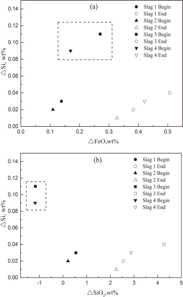
Figure 8 shows the relationship between ΔMn and ΔFeO, ΔMnO. Combining Figs. 8(a) and 8(b), under the remelting condition of the four slag systems, a negative deviation of MnO and a positive deviation of FeO from equilibrium lead to some extent of Mn-oxidation at the beginning of remelting, as the dotted line presents. In addition, with the deviation of FeO increasing, the extent of Mn-loss increases. As the reaction progress, the content of MnO in the slag increases. Therefore, the extent of Mn-oxidation has a slight downtrend compared to that at the beginning of remelting. The reaction Mn–FeO/Fe–MnO at the end of remelting is closer to the equilibrium state. In addition, the larger deviation of FeO from equilibrium, the larger extent of Mn oxidized at the end of remelting.
In conclusion, the composition variation of Al, Si, Mn and oxygen corresponds well with the deviation of Al2O3, SiO2, MnO and FeO from equilibrium, reflecting the reasonability of this model.
4. Model Application during Industrial ESR Process
The reasonability of this model has been verified through the above analysis. This model is supposed to provide some guidance for the industrial ESR operation. The design principle of the composition of electrode and slag system is all of great importance to the homogeneity of ingot. Figure 9 shows the effect of Al in the electrode and initial CaO in the slag on equilibrium compositions of FeO, MnO, Al2O3 and SiO2. The content of Si and Mn in the electrode is set as 0.33 wt%, 0.63 wt% while initial content of CaF2 and MgO in the slag is set as 45 wt%, 5 wt%, respectively.

As can be seen from Fig. 9, every group of steel components has a quantitative composition of equilibrium slag system. With the initial CaO content in the slag rising, the equilibrium SiO2 content has a pick-up while FeO, MnO and Al2O3 shows a down trend under the same Al content. Therefore, it is suggested that the CaO content in the slag should be controlled to a relatively lower content because surplus FeO with reference to equilibrium FeO content has a potential to react with Al resulting in an increase in inclusion amount. Under the same CaO content, with the increasing content of Al, the equilibrium contents of FeO, MnO and SiO2 decreases while Al2O3 has a slight increase. That is to say, high content of Al is more likely to react with the FeO, thus would also result in the increase of Al2O3 inclusions in the steel. From Figs. 5 and 6, large deviation of measured FeO from equilibrium is a key factor leading to the Al-oxidation and oxygen increase. With the increase of Al-oxidation, the oxygen content shows an obvious pick-up, reflecting that a large quantity of the formed inclusions due to the slag-metal reactions would stay in the steel. Some scholars45,46) have also proved that more insoluble alumina inclusions are observed in the metal for FeO-containing slag.
Therefore, it is suggested the content of Al in the electrode should be controlled to a relatively low level. Under the premise of one slag system with relatively low CaO content, a feasible method is to add strong deoxidizer of Al powder into slag pool to decrease the oxygen potential for that the reaction product would stay in the slag, or strengthen the protecting atmosphere, particularly during the last stage of remelting.
5. Conclusions
A thermodynamic model to design the equilibrium slag compositions during ESR process was developed based on slag-metal equilibrium theory and IMCT and the following conclusions were obtained.
(1) Given a steel composition, the slag composition balanced with the consumable electrode can be obtained quantitatively, by which one can predict how much slag-metal reactions proceed. This prediction is beneficial to the homogeneity and cleanliness of the refined ingot.
(2) The reasonability of this model was verified by an industrial experimental. It was found the composition variation of Al, Si, Mn and oxygen corresponds well with the deviation of Al2O3, SiO2, MnO and FeO from equilibrium, reflecting the reasonability of this model.
(3) This model could provide some guidance for deoxidation practice during industrial ESR process. In order to decrease the oxygen content of ingot, a feasible method is to add strong deoxidizer of Al powder into the slag pool or strengthen the protecting atmosphere, particularly during the last stage of remelting.
Acknowledgments
The authors would like to appreciate the financial support of Xining Special Steel Plant and the International Cooperation Project (No. 2015DFG51950).
References
- 1) T. R. Bandyopadhyay, P. K. Rao and N. Prabhu: Metall. Min. Ind., 4 (2012), 6.
- 2) V. Weber, A. Jardy, B. Dussoubs, D. Ablitzer, S. Ryberon, V. Schmitt, S. Hans and H. Poisson: Metall. Mater. Trans. B, 40 (2009), 271.
- 3) S. K. Matity, N. B. Ballal, G. Goldhahn and R. Kwaalla: ISIJ Int., 49 (2009), 902.
- 4) M. E. Fraser and A. Mitchell: Ironmaking Steelmaking, 3 (1976), 279.
- 5) A. Mitchell, F. R. Carmona and E. Samuelsson: Trans. Iron Steel Inst. Jpn., 24 (1984), 550.
- 6) M. Allibert, J. F. Wadier and A. Mitchell: Ironmaking Steelmaking, 5 (1978), 213.
- 7) F. R. Carmona and A. Mitchell: ISIJ Int., 32 (1992), 534.
- 8) S. F. Medina and A. Cores: ISIJ Int., 33 (1993), 1244.
- 9) S. F. Medina, F. Lopez and A. G. Coedo: Ironmaking Steelmaking, 24 (1997), 331.
- 10) S. F. Medina, F. R. Valdepenas, M. Chapa and A. Quispe: Steel Res., 69 (1998), 314.
- 11) C. S. Chai and T. W. Eagar: Metall. Mater. Trans. B, 12 (1980), 539.
- 12) C. S. Chai and T. W. Eagar: J. Mater. Energy Syst., 5 (1983), 160.
- 13) R. J. Hawkins, D. J. Swinden and D. N. Pocklinton: Proc. Conf. in Electroslag Refining, I.S.I., Iron and Steel Institute, London, (1973), 21.
- 14) G. Hoyle: Electroslag Processes Principles and Practice, Applied Science Publishers, London, (1983), 29.
- 15) P. Mellberg and H. Sandberg: Scand. J. Metall., 2 (1973), No. 3, 121.
- 16) W. Holzgruber, K. Petersen and P. E. Schneider: Trans. Int. Vacuum Metallurgy Conf., American Vacuum Society, New York, (1968), 499.
- 17) J. H. Wei and A. Mitchell: Acta Metall. Sin., 23 (1984), B132.
- 18) J. Zhang: Calculated Thermodynamics of Metallurgical Melts and Solution, Metallurgical Industry Press, Beijing, (2007).
- 19) The Japan Society for the Promotion of Science, the 19th Committee on Steelmaking: Data Sourcebook, Gordon and Breach Science Pub., New York, (1988).
- 20) J. H. Wei and A. Mitchell: Acta Metall. Sin., 20 (1984), B271.
- 21) G. K. Sigworth and J. F. Elliott: Metal. Sci., 8 (1974), 298.
- 22) C. R. Taylor and J. Chipman: Trans. AIME., 154 (1943), 228.
- 23) H. Suito and R. Inoue: ISIJ Int., 36 (1996), 536.
- 24) M. Kishi, R. Inoue and H. Suito: ISIJ Int., 34 (1994), 859.
- 25) S. Ban-ya and S. Matoba: Tetsu-to-Hagané, 48 (1962), 925.
- 26) J. Zhang and W. X. Yuan: J. Univ. Sci. Technol. Beijing, 17 (1995), 418.
- 27) P. Wang, T. W. Ma and J. Zhang: Iron Steel, 31 (1996), 27.
- 28) X. M. Yang, C. B. Shi, M. Zhang, G. M. Chai and F. Wang: Metall. Mater. Trans. B, 42 (2011), No. 6, 1150.
- 29) K. C. Mills and B. J. Keene: Int. Met. Rev., 26 (1981), 45.
- 30) M. Allibert: Slag Atlas, Verlag Stahleisen GmbH, Düsseldorf, (1995).
- 31) F. P. Glasser: J. Am. Ceram. Soc., 45 (1962), 242.
- 32) T. Watanabe, H. Fukuyama and K. Nagata: ISIJ Int., 42 (2002), 493.
- 33) M. Allibert, C. Chatillon and K. T. Jacob: J. Am. Ceram. Soc., 64 (1981), 307.
- 34) S. Kambayashi and E. Kato: J. Chem. Thermodyn., 16 (1984), 241.
- 35) J. Zhang: J. Iron Steel Res. Int., 10 (2003), 9.
- 36) B. K. D. P. Rap and D. R. Gaskell: Metall. Mater. Trans. B, 12 (1981), 311.
- 37) M. Timuçin and A. Muan: J. Am. Ceram. Soc., 75 (1992), 1399.
- 38) F. D. Richardson, J. H. E. Jeffes and G. Withers: J. Iron Steel Ins., 166 (1950), 213.
- 39) A. McLean and R. G. Ward: J. Iron Steel Inst., 204 (1966), 8.
- 40) E. T. Turkdogan: Physical Chemistry of High Temperature Technology, Academic Press, New York, (1980).
- 41) R. H. Rein and J. Chipman: Trans. Metall. Soc. AIME, 233 (1965), 415.
- 42) O. Knacke, O. Kubaschewski and K. Hesselmann: Thermochemical Properties of Inorganic Substances, Springer-Verlag, Berlin, (1991).
- 43) I. Barin: Thermochemical Data of Pure Substances. VCH Verlagsgesellschaft mbH, Weinheim, (1995).
- 44) A. Mitchell, J. Szekely and J. F. Elliott: Electroslag Refining, Iron and Steel Institute, London, (1973), 1.
- 45) H. P. Sun and K. Mori: ISIJ Int., 36 (1996), S34.
- 46) J. Fu: Acta Metall. Sin., 15 (1979), 535.


