Regular Article
Effect of Dilution on Wear Performance of Plasma Transferred Arc Deposited Layers
2017 Volume 57 Issue 5 Pages 913-920
Details
2017 Volume 57 Issue 5 Pages 913-920
The effect of dilution on the wear behavior of PTA (Plasma Transferred Arc) Inconel 625, Inconel 718, and Stellite 6 overlays on Nimonic 80A substrate were investigated. In order to evaluate the wear performance, two-body and three-body abrasive wear tests, and pin-on-disk dry sliding wear test were performed. Microstructural development during the solidification of deposits is also discussed. Wear test results show that the wear rate of deposits with 30% dilution is higher than that of deposits with 10% dilution by around 10%. The sliding wear resistance of overlay deposits follows a similar trend to the abrasive wear resistance. The wear rate of pins for the pin-on-disk dry sliding wear testing is increased as the applied stress is increased. However, the wear rate of pins initially increases sharply with increasing the sliding speed, then stabilizes with further increase in sliding speed at around 0.84 m/s. Cross sectional examinations of the worn surface of pin specimens implies that the plastic deformation near worn surface has occurred during the wear testing.
In exhaust valve spindles, the material primarily used is heat resistant Nimonic 80A alloy having a Stellite 6 alloy deposited over it.1,2) However, there is cost problems associated with the use of Stellite 6 alloy overlayed by PTAW (Plasma Transferred Arc Welding) on Nimonic 80A exhaust valve spindles. This is particularly apparent in large diesel engines, for which large exhaust valves are required. In addition, increasing demands for improved performance in engines will inevitably bring further elevated costs. Recently, the Inconel 625 and 718 alloys are being substituted for Stellite 6 due to their similar hot corrosion resistance with Stellite 6 and lower costs.
In austenitic high alloys (Inconel 625 and 718) that contain Nb and Ti, nonequilibrium solidification in the weld region promotes the partitioning of these elements to the last to solidify interdendritic regions. This segregation extends the alloy solidification range and promotes final solidification to a low melting point phase that is for Nb-rich eutectic phase. Both the increase in solidification temperature range and partitioning of melting point suppressing elements such as Nb and Ti have been shown to increase susceptibility to solidification cracking in Ni-base alloys.3)
Much works have investigated the wear behavior of Ni- and Co-base alloys with hardfacing techniques, but did not considered in detail effect of dilution between coating alloys and base metals.4,5,6,7,8,9) When a coating is overlayed on the substrate in PTAW of dissimilar materials, dilution between overlay and substrate inevitably occurs. Therefore, the chemical mixing causes the resultant microstructure to change. Since wear performance of materials depends strongly on the microstructures, it is expected that overlays with different dilution would show different wear resistance. In general, two types of eutectic type constituents, γ/NbC and γ/Laves, are known to form in Inconel 625 and 718 overlayers, and Cr-riched eutectic carbide forms in Stellite 6 alloy. The valve seat wear mechanisms were found to be a complex combination of adhesive wear/material transfer, abrasive wear, and plastic deformation.10)
This article reports on the characterization and abrasive and pin-on-disk dry sliding wear performance of Ni and Co-base alloys deposited by PTA process. Two gases atomized Ni-based powders (Inconel 625 and 718) and Co-based powder (Stellite 6) were weld surfaced by the PTA process and then evaluate their wear performance to study the effects of dilution.
The Inconel 625, Inconel 718, and Stellite 6 alloy powders were deposited using PTAW on Nimonic 80A which is used in the exhaust valve spindle. The chemical compositions and density of the alloy powders used in this study are given in Table 1. To observe the wear performance with dilution, Inconel 625, Inconel 718 and Stellite 6 PTA overlays were formed with 10% and 30% dilution by varying the parameters of PTA process.
| Materials | Chemical composition (wt.%)* | Density (mg/mm3) | |||||||||
|---|---|---|---|---|---|---|---|---|---|---|---|
| Ni | Co | Cr | Fe | W | Ti | Nb | Mo | C | Si | ||
| Nimonic 80A | Bal. | – | 17.57 | 1.43 | – | 2.50 | – | – | 0.070 | 0.016 | 8.19 |
| Inconel 625 | Bal. | – | 19.76 | 2.74 | – | 0.10 | 3.56 | 8.50 | 0.058 | 0.480 | 8.44 |
| Inconel 718 | Bal. | – | 17.71 | 17.37 | – | 1.01 | 4.97 | 2.93 | 0.045 | 0.200 | 8.19 |
| Stellite 6 | 1.64 | Bal. | 28.63 | 2.04 | 4.55 | – | – | – | 1.25 | – | 8.46 |
The parameters of PTA process are given in Table 2. The degree of mixing is defined by the percentage dilution, D:
| (1) |
| Parameters | Conditions |
|---|---|
| Torch gap (mm) | 15 |
| Primary gas flow (ℓ/min) | 6 |
| Carrier gas flow (ℓ/min) | 6 |
| Shield gas flow (ℓ/min) | 20 |
| Powder feed rate (kg/h) | 3.3 |
| Main arc current (A) | 180–220 |
| Number of Pass | Single |
| Travel speed (cm/min) | 10 |
| Oscillation speed (cm/min) | 50 |
| Oscillation width (mm) | 25 |
| Preheat temperature (°C) | 350 |

Schematic illustration of dilution in single pass welds.
Two-body abrasive wear testing was carried out using a Sugaru wear tester. Schematics of the Sugaru wear tester can be found in Refs. 19) and 20). Buehler grinding paper #400 (grit size of 30 μm) was used for counter abrasive. The width of wear track is 12 mm, and the load chosen was 3 kg. Each specimen was tested during 2400 revolutions and the weight was measured up to 0.1 mg every 400 revolutions. The average linear speed was 0.07 m/sec and the total sliding distance was 202 m. Test procedures were in accordance with JIS H 8682 specification.11)
Three-body abrasive wear resistance was evaluated using a dry sand rubber wheel (DSRW) test equipment.12) The specimens were ground using #800 emery paper before wear testing. Beach sand was used instead of Ottawa standard sand. Beach sand was sieved to 0.2–0.3 mm. Weight loss was measured up to 0.1 mg and the average of three runs for each specimen is reported. Test procedures were in accordance with ASTM specification procedure B. Specimen size for abrasive wear testing was 25 × 55 × 6(t) mm.
2.3. Sliding Wear TestingA pin-on disk tribometer was employed at room temperature (around 24°C) without lubrication to evaluate the dry sliding wear resistance. A flat-ended stationary pin specimen (ϕ 8 mm and length 15 mm) was rubbed against a rotating disk (Nimonic 80A) with ϕ 30 mm of the pitch circle diameter. Pins with PTA deposits were cut into the desired wear specimens by electro-discharge machining after PTA weld-surfacing. To reduce the period to reach the steady state during wear testing, the disks were previously ground with SiC grit paper (#800) before wear testing. Test speeds employed in this study were 0.42, 0.63, 0.84, 1.68 and 3.36 m/s, and imposed stresses were 1.49, 1.99 and 2.49 MPa. The weight lost of pin was measured after total sliding distance of 3780 m with a balance up to 0.1 mg. The average of minimum three runs for each specimen is reported.
2.4. Characterization of the CoatingCoating samples were sectioned, mounted, and polished perpendicular to the coating surface using the conventional polishing procedures. Etching for cross sectional examinations was carried out using electrolytically etching process in a solution containing 100 ml distilled water and 10 g CrO3.
Microhardness data were obtained from a conventional microhardness tester using 10 kg and 2 g load on mounted cross-sections and worn sub-surfaces of the coating samples. The hardness of PTA deposit and worn sub-surface were measured at the middle and 0.1 mm away from the worn surface, respectively. Ten points spaced of about 1 mm was measured for each layer.
The microstructure of the coatings was studied by means of optical microscope and Scanning Electron Microscope (SEM) equipped with EDS and WDS. In order to assess the dilution of PTA deposits, ten SEM photos (magnification ×1000) in each PTA deposits were selected, and then the program in image analyzer (Quantimet 570, Cambridge Instruments) gives an area fraction of eutectic constituents in this area.
Table 3 summarizes the basic properties of coatings produced by PTA process. The bulk hardness of Stellite 6 is the highest among the three alloys studied. The bulk hardness of Inconel 718 is higher by around 10 HV than that of Inconel 625 and is decreased by around 15 HV with increasing the dilution from 10% to 30% for both alloys. However, the decreased bulk hardness of Stellite 6 is still higher by around 60 HV than those of Inconel 625 and Inconel 718. It can be summarized that both all the hardness and the area fraction of the eutectic constituents are decreased with increasing the dilution.
| Specimens | Dilution (%) | Bulk hardness (Hv) | Eutectic constituent hardness (Hv) | Matrix hardness (Hv) | Eutectic constituent area fraction (%) |
|---|---|---|---|---|---|
| Inconel 625 | 10 | 210 | – | 206 | 3.3 |
| 30 | 196 | – | 194 | 2.3 | |
| Inconel 718 | 10 | 218 | – | 217 | 5.0 |
| 30 | 205 | – | 203 | 4.2 | |
| Stellite 6 | 10 | 335 | 520 | 281 | 26.3 |
| 30 | 278 | 489 | 252 | 23.1 |
Table 4 summarizes the chemical compositions of deposit layers produced by PTA process. And to identify change of the chemical compositions by dilution, calculate the chemical compositions of PTA deposit layers using Eq. (2) (Table 5). Ni contents are increased with dilution increase from 10% to 30% for all three samples. However, Co contents in Stellite 6 are decreased with increased dilution. It is seen that composition change due to dilution effect in Stellite 6 is more pronounced than that of Ni-based alloys (Inconel 625 and Inconel 718).
| (2) |
| (unit: wt.%) | |||||||||||
|---|---|---|---|---|---|---|---|---|---|---|---|
| Ni | Co | W | Cr | Fe | Ti | Nb | Mo | C | Si | ||
| Inconel 625 D10 | 64.60 | – | – | 19.91 | 2.70 | 0.13 | 3.59 | 8.53 | 0.059 | 0.475 | |
| Inconel 625 D30 | 67.38 | – | – | 20.62 | 2.26 | 0.74 | 2.75 | 6.34 | 0.067 | 0.351 | |
| Inconel 718 D10 | 58.71 | – | – | 17.43 | 16.38 | 1.09 | 4.47 | 2.61 | 0.049 | 0.203 | |
| Inconel 718 D30 | 63.84 | – | – | 18.18 | 11.87 | 1.55 | 3.47 | 1.89 | 0.058 | 0.130 | |
| Stellite 6 D10 | Matrix | 19.53 | 51.43 | 5.37 | 22.12 | 1.55 | – | – | – | NA | – |
| Eutectic constituents | 7.82 | 24.63 | 9.96 | 55.94 | 1.65 | – | – | – | NA | – | |
| Stellite 6 D30 | Matrix | 28.75 | 43.29 | 4.54 | 22.11 | 1.31 | – | – | – | NA | – |
| Eutectic constituents | 16.69 | 24.39 | 6.21 | 52.71 | ND | – | – | – | NA | – | |
*NA: Not Analyzed, ND: Not Detected, D10: 10% Dilution, D30: 30% Dilution
| Dilution (%) | Ni | Cr | Fe | Ti | Nb | Mo | C | Si | |
|---|---|---|---|---|---|---|---|---|---|
| Inconel 625 | 0 | 63.571 | 19.760 | 2.740 | 0.10 | 3.560 | 8.50 | 0.580 | 0.480 |
| 10 | 64.852 | 19.541 | 2.609 | 0.34 | 3.204 | 7.65 | 0.592 | 0.434 | |
| 30 | 67.143 | 19.301 | 2.347 | 0.82 | 2.492 | 5.95 | 0.616 | 0.341 | |
| Inconel 718 | 0 | 54.447 | 17.710 | 17.370 | 1.010 | 4.970 | 2.930 | 0.450 | 0.200 |
| 10 | 57.540 | 17.696 | 15.776 | 1.159 | 4.473 | 2.637 | 0.475 | 0.182 | |
| 30 | 61.727 | 17.668 | 12.588 | 1.457 | 3.479 | 2.051 | 0.525 | 0.145 |
Figure 2 shows typical cross-sections of as-deposited PTA weld-surfaced Inconel 625, Inconel 718 and Stellite 6. In addition to primary austenite dendrites, the alloys form eutectic type constituents (bright areas in Fig. 2) during solidification. Solidification of the weld fusion zone for Inconel 625 and Inconel 718 overlay deposits occurs to γ-austenite in a cellular-dendritic mode. The partitioning of Nb, Mo and Ti to dendrite interstices during solidification (i.e., partition coefficient, k<1) promotes appreciable compositional variations at solidification substructure boundaries and the formation of terminal eutectic constituents (γ/NbC, γ/Laves) in the last-to-solidify regions.13,14,15) The microstructure of Stellite 6 is similar to those of Inconel 625 and Inconel 178, but the area fraction of eutectic constituents is much higher and compose to network structure as seen in Fig. 2(c).

Typical cross sectional SEM images of PTA deposits (Dilution 10%). (a) Inconel 625 (b) Inconel 718 (c) Stellite 6.
Figures 3 and 4 show the results of abrasive wear tests for each coating. The weight loss as a function of the number of revolutions was linear for each specimen, starting from 400 revolutions for the two-body abrasive wear testing. As expected, both (two-body and three-body abrasive) wear resistance of the Stellite 6 is higher than that of the Inconel 625 and Inconel 718. It is also found that wear resistance of all the specimens with 10% dilution is higher than that of the specimens with 30% dilution. It is interesting to note that the wear resistance of Nimonic80A is best in two-body abrasive wear, but worst in three-body abrasive wear among samples tested.
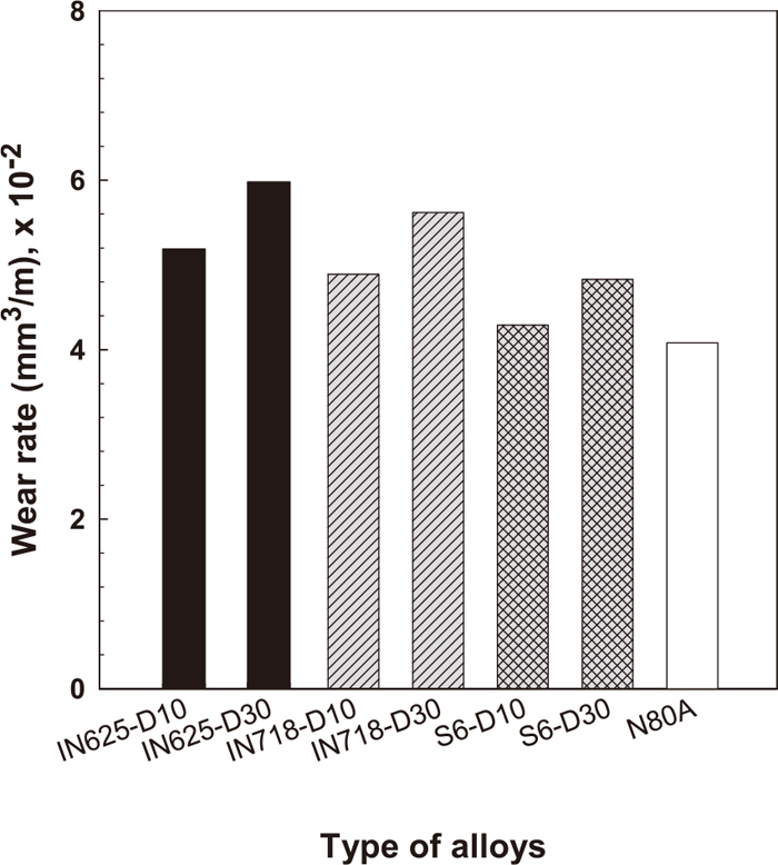
The results of two-body abrasive wear test.

The results of DSRW abrasive wear test.
Figure 5 shows the worn surface morphologies of the coatings tested by two-body abrasive wear tester with abrasive paper (grit size 30 μm). Surface damage morphology is a typical of two-body abrasive wear with microploughing in worn surfaces. Although the volume fraction of eutectic constituents of Stellite 6 is higher than that Inconel 625 and Inconel 718, wear mechanism is similar. It is supposed that the factors affecting the wear resistance of alloys with the eutectic constituents are not only eutectic constituents content, but also matrix hardness. It is expected that higher wear rate of samples gives more scratches in worn surface. However, it is hard to differentiate the wear resistance of samples from the worn surface morphologies.

Worn surface morphologies of the coatings tested by two-body abrasive wear. (a) Inconel 625/D10 (b) Inconel 625/D30. (c) Inconel 718/D10 (d) Inconel 718/D30. (e) Stellite 6/D10 (f) Stellite 6/D30.
Figure 6 shows the worn surface morphologies of the coatings tested by three-body abrasive wear tester. It is noted that worn surface morphologies of the Inconel 718 are very similar to those of the Inconel 625. The ploughing in worn surface is more severe than two-body abrasive wear test. It is also seen that surface damage is more severe in Inconel 625 than Stellite 6.

Worn surface morphologies of the coatings tested by DSRW abrasive wear. (a) Inconel 625/D10 (b) Inconel 625/D30. (c) Stellite 6/D10 (d) Stellite 6/D30.
It is known that abrasive wear resistance is governed by the volume fraction and the morphology of hard phases and the hardness of the base materials (metal matrix). It is also reported that the wear rates of specimens were generally determined by the hardness ratio of eutectic carbides and abrasive. In addition, the matrix hardness also plays an important role during microploughing.16,17) According to the results of this study, it is supposed that both the matrix hardness and eutectic fraction change by dilution are significant factors in abrasive wear.
The wear resistance of alloys can be controlled by either the matrix hardness or the eutectic constituent fraction. Eutectic constituent hardness of Stellite 6 is 520 HV with 10% dilution and 489 HV with 30% dilution. Also, matrix hardness of Stellite 6 is 281 HV with 10% dilution and 252 HV with 30% dilution. That is, hardness of both the eutectic constituent and the matrix is decreased with increased dilution for Stellite 6.
3.3. Sliding Wear Performance 3.3.1. Effect of LoadPTA deposited Inconel 625 and Stellite 6 pins were tested against the disk of Nimonic 80A (HV=320) with several sliding speed and load. Nimonic 80A was rotary forged and thus its microstructure consists of austenite with some carbides. Figure 7 shows the results of pin-on-disk wear test for both coatings with load variation. The coatings with 10% dilution exhibit better sliding wear resistance when compared to the coatings with 30% dilution for all test conditions. It is also found that Stellite 6 exhibits better sliding wear resistance than Inconel 625 at low stress level, but Inconel 625 exhibits better sliding wear resistance than Stellite 6 at high stress level. In case of Stellite 6, the effect of dilution on sliding wear performance is negligible at low stress level, but noticeable at high stress level (2.5 MPa).

The effect of applied stress on the wear rate of the pin specimens for the pin-on-disk dry sliding wear test (Sliding speed; 0.42 m/s, Total sliding distance; 3078 m).
Figure 8 shows the worn sub-surface microstructures of Inconel 625 and Stellite 6 deposits. It reveals sub-surface plastically deformed layer under the wear track (about 30 μm deep) and fragmented eutectic constituents of Stellite 6. The second phase/matrix compatibility is important factor in wear resistance. Lower matrix hardness and higher carbide hardness give better results for wear resistance.14) In this study, because matrix and eutectic carbide hardness are decreased as the dilution of the pins is increased, it seems that Stellite 6 with 30% dilution was lower wear resistance than that of Inconel 625. Figures 9 and 10 show the worn surface morphologies of Inconel 625 and Stellite 6 pin specimens after wear tests. It seems that signs of delamination wear mechanism are increased as the dilution of the pin specimen is increased. That is, the worn surface morphologies of the specimen with 30% dilution are showing more splats than those of the specimen with 10% dilution. The micrographs of worn surface and sub-surface of the Inconel 625 and Stellite 6 pins hardly reveals the materials removal from the disk suggesting that adhesive wear is not a main wear mechanism. Therefore, delamination wear as a main wear mechanism could be suggested to take place after propagation of the cracks around the splats. It is also noted that worn surface morphologies of the Inconel 625 show more scratches than those of Stellite 6 because the hardness (HV=320) of the Nimonic 80A disk is harder than that of Inconel 625 pin specimens, but similar to that of Stellite 6 pin specimens (see Table 2).

Worn sub-surface microstructures of the pin specimens after pin-on-disk dry sliding wear test (Applied stress; 2.49 MPa, Sliding speed; 0.42 m/s, Total sliding distance; 3078 m). (a) Inconel 625/D30 (b) Stellite 6/D30.

Worn surface morphologies of the pin specimens after pin-on-disk dry sliding wear test (Applied stress; 1.49 MPa, Sliding speed; 0.42 m/s, Total sliding distance; 3078 m). (a) Inconel 625/D10 (b) Inconel 625/D30.

Worn surface morphologies of the pin specimens after pin-on-disk dry sliding wear test (Applied stress; 2.49 MPa, Sliding speed; 0.42 m/s, Total sliding distance; 3078 m). (a) Stellite 6/D10 (b) Stellite 6/D30.
Figure 11 shows the results of pin-on-disk wear test for both coatings with sliding speed variation. The wear rate of Inconel 625 deposits with 10% and 30% dilution and Stellite 6 deposit with 10% dilution first increased sharply with increasing the sliding speed, and then stable with further increase in sliding speed. But, different trend is obtained for Stellite 6 deposit with 30% dilution. That is, wear rate of Stellite 6 deposit with 30% dilution is increased sharply with increasing the sliding speed, and then decreased with further increase in sliding speed, thus producing a maximum in the wear curves at an intermediate sliding speed of 0.84 m/s.

The effect of sliding speed on the wear rate of the pin specimen for the pin-on-disk dry sliding wear test (Applied stress; 1.49 MPa, Total sliding distance; 3078 m).
Figures 12 and 13 show the worn surface morphologies of the pin specimens tested by pin-on-disk wear tester for both coatings. Surface damage morphology is different from each other. That is, Inconel 625 reveals microploughing in worn surfaces and microploughing tends to be more severe as sliding speed is increased. Meanwhile, Stellite 6 reveals sign of delamination along with microploughing in worn surface and delamination is increased as the sliding speed is increased. This can be related to work hardening behavior. Figure 14 shows the result of microhardness measurements of worn sub-surface under 10 μm from worn surface. Microhardness of the Inconel 625 was increased as sliding speed is increased, but microhardness of Stellite 6 is first increased with increasing the sliding speed, and then decreased with further increase in sliding speed. That is, Inconel 625 (D10%, D30%) is gradually work hardened to sliding speed of 0.84 m/s and Stellite 6 is rapidly work hardened. Therefore, Inconel 625 deposits are continuously work hardened by ploughing, but Stellite 6 deposits are no further work hardened due to delamination.

Worn surface morphologies of Inconel 625 pin specimens with 30% dilution by pin-on-disk dry sliding wear test (Applied stress; 1.49 MPa, Total sliding distance; 3078 m). (a) 0.84 m/s (b) 3.36 m/s.

Worn surface microstructure of Stellite 6 pin specimens with 30% dilution by pin-on-disk dry sliding wear test (Applied stress; 1.49 MPa, Total sliding distance; 3078 m). (a) 0.84 m/s (b) 3.36 m/s.

The effect of sliding speed on the hardness variation of the PTA deposits worn sub surface.
According to Bhansali and Miller,18) when Nickel is substituted in cobalt-base alloys, the stacking fault energy of the Co-based alloy is increased, reduces the strain-hardening rate, lowers the stress at which cross-slip of dislocations occurs and hence increases the plasticity. This leads to galling-prone alloys and vice versa at normal wear.
In this study, when the dilution is increased, Ni content is increased and then hardness of matrix and eutectic constituent is decreased because the chemical mixing occurs between deposit and base metal (Nimonic 80A). High Ni containing alloys reveal more severe wear than low Ni containing alloys at every wear test conditions studied. It is concluded that the dilution of the deposits change matrix hardness, chemical composition, and work hardening rate and thus affect abrasive and sliding wear performance.
The main objectives of this study were to assess the dilution effect of PTA coating process on their abrasive and dry sliding wear performance. Main results are as follows.
(1) Abrasive wear resistance of Stellite 6 is higher than that of Inconel 625 and Inconel 718 at room temperature. It is also shown that the main wear mechanism is microploughing.
(2) Dry sliding wear resistance of Stellite 6 is higher than that of Inconel 625 except at high stress region. Also, the effect of dilution is negligible at low stress level, but noticeable at high stress level in case of Stellite 6.
(3) The wear rate of high diluted deposit layers was higher than that of low diluted deposit layers due to decreasing of hardness and eutectic fraction with dilution increased.
This study was conducted with specific foundation research support from KEIT (Korea Evaluation Institute of Industrial Technology).