Regular Article
Gas Permeability in Cohesive Zone in the Ironmaking Blast Furnace
2017 Volume 57 Issue 9 Pages 1531-1536
Details
2017 Volume 57 Issue 9 Pages 1531-1536
Reduction of CO2 emissions in blast furnaces is an important problem for the steel industry. Operating a blast furnace at lower CO2 levels requires a reduction in the amount of coke that is used to maintain gas permeability in the cohesive zone. Therefore, gas permeability in the iron-ore layer of the cohesive zone should be improved. In this study, gas permeability through a packed bed with liquid was measured using an experimental sponge ball packed bed as a model. The pressure drop of the sponge ball packed bed without liquid was proportional to the square of gas flow velocity. Furthermore, it was affected by the shrinkage ratio of particles. The pressure drop of the deformed packed bed with liquid was mostly affected by liquid that overflowed from the sponge balls into vacancies in the packed bed during the deformation process. This setup can simulate the phenomenon of rising pressure drop within sinter ore at the cohesive zone.
The effect of sponge ball arrangement was tested using sponge balls filled with much liquid and sponge balls with smaller amount of liquid. These sponge balls simulate gas permeability of the ore layer containing acid pellets and sintered ore in the cohesive zone. The results indicate that both the mixed arrangement and longitudinal arrangements are effective in maintaining higher gas permeability.
Modern ironmaking blast furnaces have a 300+ year-long history. However, blast furnaces consume a large amount of energy and exhaust a considerable amount of CO2. As a result, blast furnaces are slated to be gradually replaced by lower energy consuming ironmaking processes such as direct ironmaking processes and scrap melting processes. In the meantime, however, the blast furnace continues to be the most mature process for producing the large amount of molten iron that is required to meet global demand. Therefore, various methods and processes have been developed to reduce CO2 exhaust from ironmaking blast furnaces. It is important to note, however, that any reduction in CO2 exhaust necessitates a reduction in coke consumption within the blast furnace. It also requires a reduction in the coke layer that keeps vacancies in the blast furnace, and, subsequently improves gas permeability and gas-flow in the ore-layer.
Gas permeability in a blast furnace is represented by pressure drop at the cohesive zone because that is the typical area for gas permeability in the blast furnace. Therefore, many researchers have tried to express it as a numerical expression of the same.
Ono et al.1) performed softening and melting tests for several types of sinter ore and acid pellets. They arranged their experimental results for pressure drop measured at high temperature by using an equation that is derived from an empirical analysis to describe the pressure drop of gas flow through a packed bed.
| (1) |
To apply this equation to their experiment, they showed that the coefficient ‘K’ is expressed using ‘Sr (Shrinkage ratio)’ as follows.
| (2) |
Kuwabara et al.2) applied Ergun’s equation for determining the pressure drop of a packed bed to express pressure drop in their numerical gas flow model. They set the coefficient of gas flow resistance on Ergun’s equation to express gas flow in the cohesive zone.
Sugiyama et al.3) thought the Ergun’s equation was not sufficient to express pressure drop under higher shrinkage conditions. They estimated gas flow through the cohesive zone as gas flow through many orifices. It could express the deforming effect of sintered ore at the cohesive zone.
| (3) |
Takatani et al.4) compared Ergun’s equation, Ono’s equation, and Sugiyama’s equation with their experimental results. They concluded Kuwabara’s way of using Ergun’s equation fit with their experimental results. However, that the results are influenced by specific experimental conditions. It depends on the shrinkage ratio and reduction ratio.
Aforementioned studies focused on the begging of sinter ore deformation.
The shrinkage ratio of sinter ore in their studies was limited to less than 50%.
Okamoto et al.5) investigated the reducing, softening, and melting behavior of sinter ore with a BIS simulator that was developed to simulate inner blast furnace conditions.
Their experimental results show that the melting slag, composed of FeO–CaO–SiO2–Al2O3, started to overflow from sinter ore particles into vacancies at 1230°C. At this temperature, pressure drop in the sinter layer started to increase rapidly.
At this point, the shrinkage ratio of sinter ore was already over 50%. These results indicated that the pressure drop in the cohesive zone was mainly affected by melting slag containing FeO. However, previous studies have not considered the effect of melting slag on pressure drop. In this study, the target was to get basic information about pressure drop in a packed bed with liquid.
The experimental apparatus was designed as shown in Fig. 1. Sponge balls made of natural rubber were prepared to simulate the behavior of deformed sinter ore at the cohesive zone in blast furnaces. The diameter of each sponge ball was 14 mm. A total of 144 individual sponge balls were arranged in cubic rows to simulate a packed bed. The packed bed was comprised of four layers of sponge balls where each layer consisted of 36 balls arranged in a six-by-six cubic formation. The porosity of the sponge balls, as estimated from the true specific gravity of natural rubber, was 0.732. A specific volume of a glycerol-water solution was injected into each sponge ball to simulate the behavior of melting slag containing unreduced FeO. As the viscosity of melting slag in a real blast furnace is affected by the FeO concentration, the effect of viscosity was tested as well. This was achieved by varying the level of glycerol concentration in the glycerol-water solution by a wide range. Sponge balls with glycerol were put on a metallic mesh in a box, and another metallic mesh was fixed on the sponge ball packed bed. The box was elevated at a constant rate and then the packed bed was shortened between the metallic meshes. The sponge ball shrinkage rate was set to 1.2%/min because the shrinkage ratio of sinter ore observed during the softening and melting tests ranged between 1.0%/min and 2.0%/min. A specific amount of air was blown from the lower side of the box. At this time air pressure was measured upside and downside of the packed bed with digital manometers. The shrinking behavior of the sponge balls was observed continuously by video camera. Gas velocity was set to 50 to 250 L/min. When the gas velocity was higher than 100 L/min, 1 iquid did not drop off and stayed in the packed bed made of sponge balls.

Schematic drawing of the experimental equipment.

Estimation of volume of sponge balls.
The model experimental equipment requires setting dimensionless numbers closer to the value of real conditions in a blast furnace to simulate real phenomena. In this study the experimental model was prepared to specifically study gas permeability. In the case of gas flow through a tubular channel, gas permeability can be determined by measuring gas flow conditions and the shape of the flow channel. Gas flow conditions can be represented by the Reynolds number. On the other hand, the shape of the flow channel can be represented by the Weber number. In this study experimental conditions were coordinated so that these dimensionless numbers were close to them in the cohesive zone in the real blast furnace.
Experimental conditions on this experiment are listed in Table 1.
| Blast Furnace | Model Experiment | |
|---|---|---|
| Temperature [K] | 1473 | 293 |
| Particle Diameter [m] | 0.007 | 0.014 |
| Representative Shrinkage [−] | 0.5 | 0.5 |
| Liquid Density [kg/m3] | 3480 | 1222 |
| Liquid Surface Tension [N/m] | 0.41 | 0.468 |
| Gas Velocity [m/s] | 0.361 | 0.119–0.594 |
| Gas Density [kg/m3] | 1.300 | 1.226 |
| Gas Viscosity [Pa.s] | 4.96×10⁻⁵ | 1.78×10⁻⁵ |
| Reynolds Number | 56.1 | 95.4−476.7 |
| Weber Number | 6.7 | 3.1−77.5 |
The shrinkage behavior of the sponge balls was measured using another small instrument. Three balls were set vertically in a box made of acrylic resin and pressed with a metal rod from the top. While the three balls were being pressed, the change in shape of the center ball was captured by video camera (Fig. 3). After the sponge ball’s shape was measured, the volume of liquid in the sponge balls was estimated by the equation below that calculates the volume of V1,V2 and V3. The calculated sponge ball volume and vacancy in packed bed is shown in Fig. 3.
| (4) |

Deformation behavior of sponge balls.
Lastly, the effect of sponge ball arrangement on pressure drop was investigated (Fig. 4). Sponge balls containing 0.1 ml of water and 0.3 ml of water were put at the position shown in Fig. 4. Gas flow rate was set to 200 ml/min, and the liquid viscosity was set to 0.109 Pa.s.

Effect of sponge ball arrangement.
Figure 5 shows gas permeability through the deformed sponge-ball packed bed. Gas velocity was varied in this experiment. The results show that higher gas velocity resulted in a greater pressure drop. The results also show that the pressure drop of the bed increased while the packed bed was pressed. It increased gradually at first, but increased more rapidly as the shrinkage ratio went over 60%. This data was then analyzed as shown in Fig. 6. These results show that the pressure drop was proportional to the square of the gas velocity.

Pressure drop in the sponge ball packed bed without liquid.

Analysis of the experimental data on the Funning’s equation.
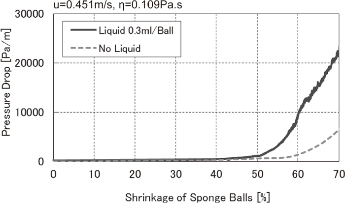
Transition of the pressure drop within the sponge-ball packed bed with viscous liquid is shown in Fig. 7. The liquid volume was set to 0.3 ml/ball to represent several conditions. The pressure drop was considerably higher in this condition than in that without liquid. These results show that the pressure drop in this test condition is mainly controlled by liquid behavior. Exudation of the liquid on the surface of sponge ball was observed when the shrinkage ratio reached 40%. When the shrinkage ratio approached 62%, the gradient of the pressure drop changed and was inhibited. This may be due to the fact that around this area liquid started to splash and a part of the liquid moved on the top of the packed bed. The flooding of the liquid was replicated.
Pressure drop in the sponge ball packed bed with liquid.
Then, the condition of the liquid was changed to check how they affected the pressure drop. At first, the concentration of the glycerol-water solution was varied to check the effect of the viscosity (Fig. 8). Despite wide variations in the viscosity of the liquid, pressure drop of the packed bed was not sensitive to this change. These results show that the viscosity of liquid does not affect the pressure drop in this condition.

Effect of the liquid viscosity on the pressure drop.
Next, the effect of liquid volume was checked. The liquid volume was changed from 0.1 ml/ball to 0.5 ml/ball. The results are shown in Fig. 9. When the shrinkage of the sponge balls was low, liquid volume didn’t affect the pressure drop because the liquid was still contained within the sponge balls. However, after the liquid exudation, the pressure drop began to rise rapidly. The point at which exudation occurred depended on the liquid volume within each ball. Moreover, as the shrinkage ratio increased past the flooding point, the rate of pressure drop increase began to slow down. These results show that while liquid volume affected the flooding point, it did not affect the rate of pressure drop increase.

Effect of the liquid volume on the pressure drop.
The mechanism for rising pressure drop of the deformed packed bed with liquid is predicted in Fig. 10. At first, the sponge balls are only partially full. They contain some amount of liquid within them, and some pores in them. When the sponge balls are pressed, liquid is pushed outward to the pores. Once the pores are filled, the liquid starts to flood out from the balls. As the vacancies between balls are filled with liquid, the pressure drop of the packed bed starts to rise rapidly. Before the liquid can fill all the vacancies, gas flow starts to push a part of liquid out of the packed bed. This is referred to as the flooding point. Once this occurs, gas flow can maintain a flow path in the packed bed, resulting in a decrease in the pressure drop rising rate.

Estimation of the pressure drop rising mechanism.
To verify this hypothesis, pressure drop of the sinter layer was simulated (Fig. 11).

Simulation of the pressure drop based on the estimation.
Volume of pressed sponge balls was estimated as shown in Fig. 10, and the initial porosity of sponge balls was calculated. It was assumed that the difference of the volume of sponge balls after shrinkage decreased the pore volume in the sponge balls. When the pore volume became smaller than that of the liquid, the liquid started to flood out from sponge balls. The estimated pressure drop can be used to simulate the phenomenon of increasing pressure drop.
4.2. Effect of Sponge Ball Arrangement on Pressure DropSintered ore and acid pellets generate molten slag when they are reduced at the cohesive zone in a blast furnace. Hotta et al.6) investigated the behavior of sintered ore and acid pellets in a blast furnace using the loading and softening test equipment that can simulate loading condition, gas pressure, gas composition and temperature in a blast furnace. They reported that acid pellets produced a larger amount of slag liquid than sintered ore at higher temperatures between 1300°C to 1400°C. At these temperatures, the shrinkage of the ore layer ranged from 40% to 60%.
Sponge balls filled with much liquid and sponge balls with smaller amount of liquid were prepared to simulate the behavior of acid pellets and sintered ore. The effect of this arrangement on the pressure drop at the cohesive zone was simulated using the experimental model (Fig. 12).

Effect of sponge ball arrangement on the pressure drop.
Under conditions where the shrinkage ratio was less than 60% and more than 40%, it was shown that mixed arrangement and longitudinal arrangement can maintain higher gas permeability. Results indicated that gas permeability through the ore layer composed of acid pellets and sintered ore could be improved by mixing charge or longitudinal charge.
The mechanism for maintaining lower pressure drop was estimated as follows in Fig. 13.

Estimated mechanism of the effect of sponge ball arrangement.
In case of layer- by- layer arrangement, each gas flow channel was closed by molten slag from the acid pellets and caused a greater pressure drop through the layer. In the case of mixed arrangement, a portion of molten slag from the acid pellets flowed into the pores of the sintered ore. The resulting reduction in molten slag within the flow channels caused a reduction in pressure drop through the ore layer. Moreover, in the case of longitudinal arrangement, gas could not flow though the acid pellet layer easily. However, gas could flow through the sintered ore layer, thereby maintaining higher gas permeability through the ore layer.
Okumura et al.7) tested the effect of acid pellet and sintered ore arrangement. Pressure drop through the ore layer at high temperature was measured using loading and softening equipment. The results indicated that a mixed arrangement of sintered ore and acid pellets could maintain lower pressure drop, similar to the results from our work with the experimental model. The results indicate that the effect of ore arrangement on pressure drop at the cohesive zone can be explained using a simple model comprised of deformed sponge balls and liquid.
Pressure drop in the iron ore layer at the cohesive zone in a blast furnace was studied using a simple experimental model composed of sponge balls and viscous liquid. The pressure drop of sponge balls without liquid was proportional to the square of gas flow velocity. Furthermore, it was shown to be affected by the shrinkage ratio of particles. The pressure drop of deformed sponge balls with liquid was primarily affected by the overflow of liquid from the deformed sponge balls, themselves. This setup simulated the phenomenon of increasing pressure drop of sinter ore at the cohesive zone.
The effect of sponge ball arrangement on pressure drop was tested using sponge balls filled with much liquid and sponge balls with smaller amount of liquid. This setup simulated gas permeability of the ore layer containing acid pellets and sintered ore in the cohesive zone. The results indicated that mixed arrangement and longitudinal arrangement were both effective in maintaining higher gas permeability.
L: Length of the sponge ball layer [m]
Dp: Diameter of sponge balls [m]
Sr: Shrinkage ratio of the sponge ball layer [-]
Cm: Orifice coefficient
u: Gas velocity [m/s]
η: Liquid viscosity [Pa.S]
gc: Gravitational acceleration constant [m/s2]
ρg: Gas density [kg/m3]
V: Volume of a sponge ball [m3]
V1: Volume of the center part of a sponge ball [m3]
V2: Volume of the upper part of a sponge ball [m3]
V3: Volume of the lower part of a sponge ball [m3]