Steelmaking
Recovery of Phosphorus from Modified Steelmaking Slag with High P2O5 Content via Leaching and Precipitation
2018 Volume 58 Issue 5 Pages 833-841
Details
2018 Volume 58 Issue 5 Pages 833-841
The P contained in steelmaking slag is regarded as a potential phosphate source, especially with regard to slag with high P2O5 content, which is generated from the utilization of high P iron ores. If P can be efficiently extracted from slag, the obtained P can be used as a phosphate fertilizer. Moreover, the remaining slag can be recycled inside the steelmaking process. Compared with other phases, the P-condensed C2S–C3P solid solution in slag is more easily dissolved in water; therefore, selective leaching was applied to recover P from slag with high P2O5 content. In this study, the effect of K2O modification on P dissolution in the citric acid solution was investigated, and subsequently, a process for extracting phosphate product from the leachate, via precipitation, was explored. It was determined that K2O modification promoted dissolution of the solid solution, resulting in a higher dissolution ratio of P. By modification, the majority of the solid solution was dissolved at pH 6, and other phases remained in residue, indicating that a better selective leaching of P occurred. As the pH decreased, the dissolution ratios of both P and Fe increased. Following leaching at pH 5, a residue with a higher Fe2O3 content and lower P2O5 content was obtained. When the pH of the leachate increased, the dissolved P in the aqueous solution was precipitated. Through separation and calcination, a phosphate product with a P2O5 content of 30% was obtained, which has the potential to be used as a phosphate fertilizer.
Steelmaking slag, including dephosphorization slag, is an important by-product of steelmaking, with more than 14 million tons produced in Japan alone in 2015.1) Steelmaking slag contains considerable quantities of valuable elements, such as P, Mn, and Fe. Although P is detrimental to the deformability of steel, it is an important strategic resource for agricultural food production. In particular, increased demand for food, owed to global population growth, consequently increases the demand for P. Because of the depletion of high-grade natural phosphate ores, the P hidden in steelmaking slag is regarded as a secondary phosphate source.2) Consequently, with regard to the steelmaking industry, it is important to develop an efficient method to recover P from steelmaking slag to lower production costs and save resources. Several methods have been explored. Li and Ishikawa et al.3,4) attempted to reduce dephosphorization slag using a slag regenerator; P was reduced and concentrated in hot metal, and was further dephosphorized to produce fertilizer material. Yokoyama et al.5) proposed a magnetic-separation method to separate and recycle the P-rich phase from steelmaking slag, by exploiting the differences in their magnetic properties.
Over the past decade, owing to the sharp increase in steel production, iron ores worldwide are steadily deteriorating in quality while prices remain at a high level. Therefore, it is inevitable that the use of low-grade iron resources will be extended in the future. Large reserves of iron ores with high P content are considered potential alternative resources.6) During their use, the P content in hot metal will increase. After dephosphorization, the majority of the P is concentrated in slag and steelmaking slag with high P2O5 content will be generated.7) Compared with traditional slags, this slag is considered more suitable for the production of phosphate fertilizer because of its high P2O5 content. If it was technically feasible to recover P from slag, the utilization of high P iron ores would be extended, securing supplies of phosphate sources. Based on this information, this study focused on developing an efficient and economical method of separating and recovering P from steelmaking slag with high P2O5 content.
Dephosphorization slag primarily consists of a CaO–SiO2–FetO–P2O5 system; it is a typical multiphase slag, which is saturated with dicalcium silicate (2CaO·SiO2). The 2CaO·SiO2 can absorb the dephosphorization product of 3CaO·P2O5 to form a 2CaO·SiO2-3CaO·P2O5 solid solution (C2S–C3P) at steelmaking temperatures.8) The high distribution ratio of P2O5 between the C2S–C3P solid solution and matrix phase indicates that P is mainly concentrated in the solid solution, even in slag with high P2O5 content.9) Hence, the process used to separate the C2S–C3P solid solution from the matrix phase is the same as that used to separate P from Fe contained in the matrix phase. Teratoko and Kitamura10) determined that at a constant pH, the solubility of elements from the matrix phase, in the nitric acid (HNO3) solution, was lower than that from the solid solution; they clarified that it was possible to dissolve a solid solution containing P without dissolving the matrix phase. They also found that the dissolution ratio of C2S–C3P decreased greatly when the P2O5 content was high. Based on such selective leaching, to increase the dissolution ratio of P from slag, we conducted a series of experiments to study the dissolution behavior of C2S–C3P solid solution, and a synthesis slag with high P2O5 content, in aqueous solutions.11,12,13) It was determined that citric acid (H3C6H5O7) exhibited a superior performance with regard to promoting dissolution of the C2S–C3P solid solution compared with that of nitric acid. By reducing cooling rate of the molten slag, as well as Na2O modification, the selective leaching of P from slag was facilitated. This is because the dissolution of solid solution was enhanced, and the dissolution of matrix phase was suppressed.
K2O has similar chemical properties to those of Na2O; it is also an important fertilizer constituent. To investigate the effects of the modification of slag with K2O on the dissolution and recovery of P, in present study, a slag with high P2O5 content was modified by the addition of K2O, and then leached in the citric acid solution under various pH conditions. Chemical precipitation methods are commonly employed during phosphate fertilizer production, and used to recover P from wastewater.14) To recover the P dissolved in the leachate, a process for extracting the phosphate product via precipitation was explored.
To prepare a steelmaking slag for a CaO–SiO2–Fe2O3 system, reagent-grade SiO2, Fe2O3, Ca3(PO4)2, MgO and K2CO3 were fully mixed, along with CaO, and heated in a Pt crucible under an air atmosphere. To produce CaO, reagent-grade CaCO3 was heated at 1273 K for 10 h in an Al2O3 crucible under an air atmosphere. Fe2O3 was used as the iron oxide because the dissolution ratio of P from this slag was greater than that from a CaO–SiO2–FeO system slag.10) The compositions of the slags with varying mass ratios of K2O are shown in Table 1. These slags were initially heated at 1823 K for 1 h to form a homogeneous liquid phase. Subsequently, the slag was cooled to 1623 K at a cooling rate of 3 K/min and held at this temperature for 20 min to precipitate solid solution. Finally, the slag was cooled in furnace at a rate of 5 K/min, and was removed from the furnace at 1323 K. The composition of each phase in the slag was measured using an electron probe micro analyzer (EPMA). In addition, the precipitated phases were determined using X-ray diffraction (XRD) analysis.
| Sample | CaO | SiO2 | Fe2O3 | P2O5 | MgO | K2O |
|---|---|---|---|---|---|---|
| 1# Slag | 37.0 | 23.0 | 29.0 | 8.0 | 3.0 | 0 |
| 2# Slag | 34.5 | 21.5 | 29.0 | 8.0 | 3.0 | 4.0 |
| 3# Slag | 32.1 | 19.9 | 29.0 | 8.0 | 3.0 | 8.0 |
The experimental procedure used for the leaching was similar to that used in previous studies.11,12) During the procedure, 1 g of the ground sample (with particles smaller than 53 μm) was put into a Teflon vessel containing 400 ml of ion-exchanged water. The aqueous solution was agitated at a speed of 200 r/min and its temperature was maintained at 298 K using an isothermal water bath. The dissolution of the Ca from slag increases the pH; therefore, to maintain the pH at a constant value, a pH meter was immersed, and citric acid, as a leaching agent, was automatically supplied using a PC control system. A schematic of the leaching system is shown in Fig. 1. At appropriate intervals, approximately 5 mL of the aqueous solution was sampled, and filtered using a syringe filter (< 0.45 μm). The concentration of each element in the filtered aqueous solution was analyzed using inductively coupled plasma-atomic emission spectroscopy (ICP-AES). During this study, three kinds of slags were leached at pH values of 5, 6, and 7, respectively. After the experiment, the leachate was separated from residue by filtering. The residue was dried, and then its mass and composition was measured. The leachate was used in the following experiment to recover P.

Schematic of the leaching system.
The leachate was treated, via the following procedure, to recover P, as shown in Fig. 2. To precipitate the dissolved P, the pH of the aqueous solution should be increased. In this study, saturated Ca(OH)2 and NaOH solutions (1 mol/L) were selected and added to the leachate to adjust the pH to a value of approximately 11, respectively. Subsequently, the cloudy solution was settled for 24 h to separate the flocculent precipitate and aqueous solution. Following the removal of the upper solution, the concentrated precipitate was dried at 373 K until a solid product was formed. To remove crystal water and get a crystalline substance, the obtained precipitate was placed in a Pt crucible and further calcined at 873 K for 2 h. The compositions of the phosphate products were analyzed using XRD, and the contents of the key elements were determined using ICP-AES.

Experimental procedure of extracting phosphate product from leachate.
The typical mineralogical structure of each slag with various K2O contents, and the composition of each phase, analyzed using EPMA, is shown in Fig. 3 and Table 2, respectively. In the case of no modification, three phases were observed in slag. Except solid solution, a magnesioferrite phase was precipitated from the matrix phase during slow cooling. A high distribution ratio of P2O5 was determined between the solid solution and other phases. In contrast, Fe was mainly distributed in the matrix phase and magnesioferrite phase. Similar conditions were also observed in the case of the modified slags. Moreover, in these slags, a number of small solid solution particles, which had a lower P2O5 content than the large solid solution particles, were observed to surround the magnesioferrite phase. The added K2O was distributed into the solid solution, and its content was lower than that in the matrix phase. With the increase in K2O content in slag, the K2O content in the solid solution increased; however, the P2O5 content decreased. In the case of the matrix phase, the K2O addition resulted in a decrease in CaO and SiO2 contents, corresponding to an increase in the Fe2O3 content.

Mineralogical structure of slags with different K2O contents.
| Sample | CaO | SiO2 | Fe2O3 | P2O5 | MgO | K2O | Phase | |
|---|---|---|---|---|---|---|---|---|
| 1# Slag (0% K2O) | A | 1.3 | 0.1 | 88.1 | 0.0 | 10.5 | 0.0 | Magnesioferrite |
| B | 40.0 | 34.8 | 21.5 | 1.8 | 1.9 | 0.0 | Matrix phase | |
| C | 54.9 | 11.8 | 1.1 | 31.3 | 0.9 | 0.0 | Solid solution | |
| 2# Slag (4% K2O) | A | 2.0 | 0.2 | 86.2 | 0.1 | 11.3 | 0.1 | Magnesioferrite |
| B | 32.1 | 33.5 | 25.6 | 1.8 | 1.6 | 5.4 | Matrix phase | |
| C | 54.6 | 17.4 | 1.3 | 23.3 | 0.5 | 2.9 | Solid solution | |
| D | 54.0 | 27.0 | 3.2 | 10.9 | 1.1 | 3.9 | ||
| 3# Slag (8% K2O) | A | 1.6 | 0.2 | 85.4 | 0.0 | 12.4 | 0.3 | Magnesioferrite |
| B | 23.0 | 31.4 | 32.8 | 0.6 | 1.2 | 11.0 | Matrix phase | |
| C | 51.6 | 18.8 | 1.1 | 20.1 | 0.3 | 8.2 | Solid solution | |
| D | 55.5 | 25.4 | 2.6 | 10.8 | 0.5 | 5.3 | ||
The mass fractions of each phase in slag were estimated using the above EPMA results. To simplify calculation, we disregarded a small portion of the small solid solution particles with low P2O5 content. The mass balance of each oxide can be represented using Eq. (1)
| (1) |
| (2) |
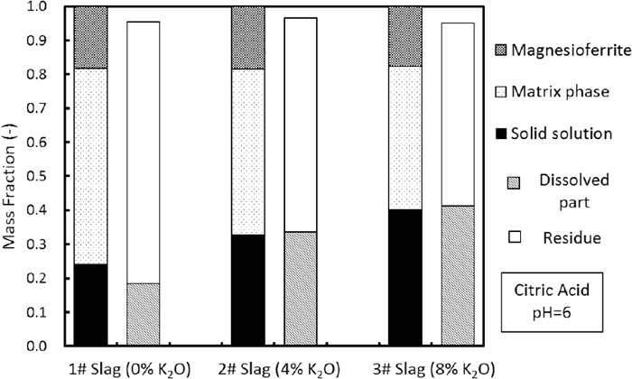
Mass fractions of residue and dissolved part, compared with the phase fractions of each slag.
The dissolution reaction of solid solution is expressed in Eq. (3).10) The change in the concentration of each element in the aqueous solution at pH 6 is shown in Fig. 4. The concentrations of Ca, Si, and P increased rapidly in 20 min; however, following 60 min, the dissolution rate of slag decreased. When the K2O addition was 4 mass%, the concentrations of Ca, Si, and P significantly increased, and a further increase in the K2O content resulted in further increases in their concentrations. Compared with other elements, the concentration of Fe was only several mg/L in each case.
| (3) |

Change in the concentration of each element in the aqueous solution at pH 6.
On the basis of the results shown in Fig. 4, the dissolution ratios of each element at 120 min were calculated using the following equation:
| (4) |

Dissolution ratios of each element from different slags at pH 6.
To determine the optimum conditions for selective leaching, the dissolution behaviors of each slag under various pH conditions were also investigated. The dissolution ratios of P and Fe, which can represent the dissolution behavior of the solid solution and other phases, respectively, are shown in Fig. 6. This figure shows that the dissolution ratio of P was far greater than that of Fe in each case. As the pH decreased, the dissolution ratios of P and Fe both increased; however, the associated trend differed for each slag. At pH 7, with a K2O addition of 4 mass%, the dissolution ratio of P increased from 25.8% to 40.1%. However, a further increase in the K2O content did not significantly promote the dissolution of P. As described in previous studies,13) Ca2+ and phosphate ions react easily and form Ca10(PO4)6(OH)2 (hydroxyapatite, HAP) at higher pH condition (expressed in Eq. (5)), which determines the P concentration. Figure 7 shows the solubility line of HAP and experimental results. At pH 7, the observed points of the modified slags were located above the solubility line of HAP, indicating that the P concentration reached saturation and a further dissolution of P was hindered by HAP precipitation.
| (5) |

Change in the dissolution ratios of P and Fe with pH.

Solubility line of HAP and experimental results at various pH conditions.
When the pH decreased to 6, the concentration of H+ ions increased, which facilitated dissolution of the solid solution. In this case, as shown in Fig. 7, the solubility line of HAP moved to the high concentrations of Ca and P, indicating that it was difficult for HAP precipitate to form. Therefore, the dissolution ratio of P from each slag increased significantly. In the case of the unmodified slag, the dissolution ratio of P exhibited a significant improvement when the pH decreased to 5; however, the dissolution ratio of Fe also increased dramatically, reaching 20.4%. This illustrates that some of the matrix phase also dissolved, which is detrimental for selective leaching. In the case of the modified slags, the dissolution ratio of P increased slightly at pH 5, and the dissolution of Fe occurred at low level; this indicates that the dissolution of matrix phase was suppressed. Hayashi et al.15) reported that Fe3+ ions in silicate glasses have two possibilities of being tetrahedrally and octahedrally coordinated; the fraction of Fe3+ in tetrahedral symmetry is larger for the SiO2–Na2O–Fe2O3 system than that for the SiO2–CaO–Fe2O3 system. Therefore, it is reasonable to speculate that the structure of matrix phase became more stable as a result of Na2O addition. Because alkaline oxides (Na2O and K2O) have the similar chemical properties, it is considered that K2O modification has the same effect on suppressing dissolution of the matrix phase. In summary, the addition of K2O is beneficial for selective leaching of P from slag.
The microstructure and composition of the residue obtained after leaching at pH 6 are shown in Fig. 8 and Table 3, respectively. Two main phases were identified in each residue. The white-colored area, rich in Fe2O3 and MgO, is the magnesioferrite phase. The grey-colored phase, consisting of a CaO–SiO2–Fe2O3 system, is considered the matrix phase. Compared with the results in Table 2, the compositions of these phases in the residue were almost identical to those in the slag prior to leaching. In each residue, it is difficult to detect the solid solution, indicating that the solid solution that had contacted with the aqueous solution had dissolved. For the residue of the modified slags, some holes could be observed near the magnesioferrite phase. These areas are considered to be the small solid solution particles that were observed prior to leaching.

Microstructure of residue after leaching at pH 6.
| CaO | SiO2 | Fe2O3 | P2O5 | MgO | K2O | ||
|---|---|---|---|---|---|---|---|
| Residue (1# Slag, pH=6) | A | 40.1 | 35.6 | 20.1 | 2.2 | 1.9 | 0.0 |
| B | 1.3 | 0.3 | 87.6 | 0.0 | 10.8 | 0.0 | |
| Residue (2# Slag, pH=6) | A | 31.8 | 35.5 | 23.5 | 2.0 | 1.8 | 5.3 |
| B | 1.7 | 0.7 | 85.3 | 0.1 | 12.1 | 0.1 | |
| Residue (3# Slag, pH=6) | A | 23.2 | 32.0 | 31.6 | 0.9 | 1.5 | 10.8 |
| B | 0.9 | 2.8 | 83.0 | 0.1 | 13.0 | 0.2 |
Figure 9 shows the XRD patterns for the slags and their residues after leaching at pH 6. In each slag, the precipitated solid solution and magnesioferrite phase were observed. The crystal form of the solid solution was changed because of K2O modification. After leaching, the intensity of the peaks associated with solid solution weakened, and that of the magnesioferrite phase increased. In the case of the residue of the unmodified slag, peaks associated with the solid solution still existed. However, for the modified slags, the peaks associated with the solid solution almost disappeared, indicating that the dissolution and separation of the solid solution were enhanced by K2O modification.

XRD patterns for the slags and their residues after leaching at pH 6.
The average composition of each residue was analyzed using ICP, as shown in Table 4. Compared with the initial slag prior to leaching, the CaO, SiO2, and P2O5 contents in each residue reduced; however, the Fe2O3 and MgO contents increased. After leaching at pH 6, with the increase in K2O content, the P2O5 content of the residue decreased because of an increase in the dissolution ratio of P. The undissolved Fe remained in the residue, and its content correspondingly increased. When the pH decreased to 5, the P2O5 and Fe2O3 contents of the residue further decreased and increased, respectively; this is beneficial for the recycling of slag in steelmaking process. From the above findings, it can be determined that the P-condensed solid solution was easily dissolved compared with other phases in aqueous solutions, and could be separated from slag via leaching.
| Residue | CaO | SiO2 | Fe2O3 | P2O5 | MgO | K2O |
|---|---|---|---|---|---|---|
| 1# Slag (pH=6) | 34.22 | 22.37 | 36.29 | 3.36 | 3.75 | 0.00 |
| 2# Slag (pH=6) | 24.01 | 18.15 | 46.37 | 2.05 | 4.67 | 4.75 |
| 3# Slag (pH=6) | 16.12 | 17.99 | 51.06 | 1.47 | 5.16 | 8.21 |
| 1# Slag (pH=5) | 20.63 | 18.24 | 54.54 | 1.05 | 5.55 | 0.00 |
| 2# Slag (pH=5) | 21.98 | 18.35 | 48.84 | 1.29 | 4.87 | 4.68 |
| 3# Slag (pH=5) | 13.85 | 16.20 | 55.37 | 0.66 | 5.58 | 8.36 |
Assuming that only the solid solution is dissolved, the dissolution ratios of Ca, Si, and P can be calculated using the mass fraction and the composition. The calculated values are shown in Fig. 10; these are also compared with the experimental results obtained at pH 6. The observed dissolution ratio of P was lower than the calculated value in each case, indicating that not all of the solid solution dissolved. With the increase in K2O content, the observed value gradually approaches the calculated values. This shows that the dissolution of solid solution was promoted. It is well known that K3PO4 and Na3PO4 are soluble in water, while Ca3(PO4)2 is insoluble; in addition, the 2CaO·Na2O·P2O5 shows a higher solubility than 3CaO·P2O5 in the 2% citric acid solution.16) Consequently, the introduction of K2O is considered to enhance the solubility of solid solution, resulting in a higher dissolution ratio. The dissolution ratios of Ca and Si were closed to the calculated values, and slightly greater than the calculated values when K2O modification was introduced. This shows that a portion of the dissolved Ca and Si was supplied from the matrix phase. Because the difference was not great, it is considered that the dissolution of matrix phase was not significant. The lower dissolution ratio of Fe could also confirm from this point.

Calculated dissolution ratios of each element from solid solution comparing with the experimental results.
Following leaching, the masses of the residue and the dissolved portion, calculated using the dissolution ratio, were compared with the phase fractions of the initial slag in Fig. 11. In the case of the unmodified slag, the dissolved mass was lower than the mass fraction of solid solution, indicating that a portion of the solid solution remained in the residue. With the increase in K2O addition, the dissolved mass increased, and its value was almost identical to the mass fraction of solid solution. Combined with above analysis, it could be concluded that the majority of the solid solution had dissolved, and little dissolution of other phases occurred. Enhanced selective leaching of the P-condensed solid solution was achieved.
3.3. Phosphorus RecoveryThe leachate, after the leaching of slag with 4 mass% of K2O at pH 6, was used for P recovery. The composition of each element in the leachate is listed in Table 5. Owing to selective leaching, the Ca, Si, and P concentrations are high, and the Fe and Mg concentrations are low. Following the addition of the alkaline solution, and the precipitation, the concentration of each element in the upper solution were compared with those in the leachate in Table 5. This shows that the P concentration was reduced significantly. The P precipitation ratio was estimated using Eq. (6), where, YP is the P precipitation ratio, C1 is the P concentration in the leachate, and C2 is the P concentration in the upper solution after precipitation. When Ca(OH)2 was added, there was little change in the Ca concentration, and the P precipitation ratio reached 99.6%. When NaOH was added, the Ca concentration was reduced by half, and the P precipitation ratio was 96.0%. There was a little decrease in the Si and K concentrations in both cases.
| (6) |
| Ca | Si | P | Fe | Mg | Na | K | |
|---|---|---|---|---|---|---|---|
| Leachate | 328.37 | 73.49 | 65.16 | 5.02 | 4.05 | 0.78 | 25.12 |
| Solution (adding Ca(OH)2) | 307.50 | 49.20 | 0.24 | 0.10 | 1.38 | 0 | 19.60 |
| Solution (adding NaOH) | 155.66 | 61.6 | 2.62 | 0.16 | 0.56 | 422.72 | 21.36 |
It is well known that in solutions containing Ca and phosphate ions, a number of calcium phosphate phases such as dicalcium phosphate dihydrate (DCPD, CaHPO4∙2H2O), octacalcium phosphate (OCP, Ca8H2(PO4)6∙5H2O), tricalcium phosphate (TCP, Ca3(PO4)2), and HAP (Ca10(PO4)3(OH)2), may form depending on the pH and solution composition.17) The precipitation reactions of these calcium phosphates are described in Eqs. (7), (8), (9), (10).18,19) On the basis of their equilibrium constants, the solubility curves of these calcium phosphates in aqueous solutions were calculated at pH 11. Figure 12 shows the compositions of the leachate and that of the solution after precipitation. After the addition of NaOH, the solution composition was located at the solubility curve of DCPD; in the case of Ca(OH)2 addition, it was located between the solubility curve of DCPD and OCP. This shows that the precipitated calcium phosphate may consist of DCPD or OCP. Considering the thermodynamics, HAP is determined to be the most stable calcium phosphate, and the P concentration in the solution can be reduced to a much lower value. However, the precipitation of unstable compounds, as precursors, is commonly observed owing to the differences in the kinetic condition of nucleation.17) In many natural environments, DCPD, along with OCP and TCP, plays a crucial role as a precursor or intermediate to HAP.20) Therefore, the P concentration in the upper solution is considered to be determined by the solubility values of DCPD and OCP.
| (7) |
| (8) |
| (9) |
| (10) |

Solubility curves for some calcium phosphates and the experimental results at pH 11.
Figure 13(A) shows an image of the precipitate obtained through the addition of Ca(OH)2. Table 6 shows the composition of the precipitate. These two precipitates mainly consist of CaO and P2O5; the K2O content is very low. The precipitate also has SiO2 and Fe2O3 contents of 3–5 mass% and 1.0% mass%, respectively. When NaOH was added, the obtained precipitate had a higher P2O5 content and lower SiO2 content. However, according to the mass balance calculation, approximately 20 mass% of the precipitate was determined to be unknown. This constituent was considered to be crystal water and organic substance (citrate).

Image of the precipitate and phosphate product when Ca(OH)2 was added.
| Sample | CaO | SiO2 | P2O5 | Fe2O3 | Na2O | MgO | K2O | Others | |
|---|---|---|---|---|---|---|---|---|---|
| Precipitate | Ca(OH)2) | 41.94 | 5.42 | 23.30 | 1.10 | 0.03 | 0.63 | 0.06 | 27.52 |
| NaOH | 41.87 | 3.29 | 24.97 | 1.17 | 1.96 | 0.97 | 0.11 | 25.66 | |
| Phosphate product | Ca(OH)2) | 53.53 | 5.86 | 28.52 | 1.40 | 0.01 | 0.80 | 0.10 | 9.78 |
| NaOH) | 52.59 | 3.47 | 30.38 | 1.49 | 2.59 | 1.22 | 0.16 | 8.10 | |
Following calcination, the white precipitate transformed into a grey phosphate product, as shown in Fig. 13(B). The compositions of these phosphate products are also listed in Table 6. Compared with those of the precipitate, the contents of each constituent all increased because of the removal of the crystal water and the decomposition of the organic substance. When NaOH was added, the P2O5 content in the final phosphate product reached 30.4 mass%, which is similar with that in some commercial phosphate fertilizers.21) Figure 14 shows the XRD patterns for the phosphate product. The main peaks of these two products are almost identical. The peaks were consistent with those of silicon−substituted calcium hydroxyapatite (Ca5(PO4)2.85(SiO4)0.15(OH)) and HAP (Ca10(PO4)6(OH)2). This shows that, following calcination, the phosphate that was precipitated from the leachate finally existed in the form of HAP. As shown in Fig. 12, the most stable calcium phosphate is HAP. There is also evidence to show that ultimately, any calcium phosphate that is precipitated will probably transform into the thermodynamically more stable HAP.22) In summary, the addition of Ca(OH)2 or NaOH solution into the leachate has similar effects on phosphate precipitation, and an identical HAP product is obtained. The obtained precipitate or phosphate product has the potential to be used as a fertilizer, because they have the same components (CaO and P2O5) as phosphate fertilizer and a high enough P2O5 content.21)

XRD patterns for the obtained phosphate products.
In this study, a process for the comprehensive utilization of slag with high P2O5 content and waste-free steelmaking was proposed, which is outlined in Fig. 15. During a conventional ironmaking process, hot metal with high P content will be generated because of the reduction of high P iron ores. First, it is dephosphorized in a converter. During this process, alkaline oxide (Na2O or K2O) is added as a flux to increase the phosphate capacity of slag.23) Following dephosphorization, the hot metal is decarburized with a smaller amount of slag, and molten steel is produced. The slag with high P2O5 content is oxidized, and then treated via selective leaching. The P in this slag is dissolved and concentrated in the leachate. The leaching residue and decarburization slag, with a lower P2O5 content and higher Fe2O3 content can be returned to the dephosphorization process. The soluble phosphate in the leachate is precipitated in the form of calcium phosphate, which can be used as a fertilizer. No extra slag is discharged during this steelmaking process.

A process for the comprehensive utilization of slag with high P2O5 content.
To recover P from steelmaking slag with high P2O5 content, the effects of K2O modification of slag on selective leaching of P in the aqueous solution were investigated, and then a process for extracting phosphate product from the leachate, via precipitation, was explored. The following results were obtained:
(1) By K2O modification, a portion of the K2O was distributed into the P-rich solid solution, and the mass fraction of the solid solution in slag increased; however, the P2O5 content in the solid solution decreased.
(2) K2O modification promoted dissolution of the solid solution in the aqueous solution, resulting in higher dissolution ratios of Ca, Si, and P. In the case of the modified slag, the majority of the solid solution was dissolved at pH 6, and other phases remained in the residue, indicating that selective leaching of P from slag was more efficient.
(3) As the pH decreased, the dissolution ratios of P and Fe both increased. At pH 5, more than 80% of the P was dissolved from each slag. Following K2O modification, the dissolution of the matrix phase was significantly suppressed, resulting in a lower Fe dissolution ratio. A residue with a higher Fe2O3 content and lower P2O5 content was obtained after leaching.
(4) When the pH of the leachate increased because of the addition of alkaline solution, the dissolved P in the aqueous solution was almost precipitated. Through separation and calcination, a phosphate product with a P2O5 content of approximately 30 mass% was obtained; it has the potential to be used as a phosphate fertilizer. Moreover, a process for the comprehensive utilization of high P iron ores, and waste-free steelmaking, was proposed.