Abstract
The main objective of the present work was to investigate the forced wetting of a partly oxidized steel by a liquid Zn–Al (0.2 wt.%) alloy. The wetting experiments are performed by means of the dispensed drop technique. The wetting is shown to be reactive with the formation of Fe2Al5Znx. The evolution of the contact angle and spreading diameter is determined as a function of spreading time.
The final contact angle lies between the receding and the advancing contact angle and is a decreasing function of the initial kinetic energy of the droplet. The liquid zinc drop remains pinned in a metastable position, due to the contact angle hysteresis.
During the first ms, the spreading diameter increases up to its maximal value Dmax. In good agreement with previous studies in the field of wetting at low temperatures, the maximal spreading diameter scales as D0 We1/4, We being the Weber number which compares inertial and capillary forces.
The kinetic energy of the liquid metal droplet needed to reach the minimum receding contact angle was predicted from the model based on the Weber number to describe Dmax. This kinetic energy is in good agreement with the experimental results.
As a final conclusion, an increase in the initial kinetic energy of the droplet leads to a decrease in the final contact angle. It is therefore expected that forced wetting could improve the galvanizability of steels by liquid Zn–Al alloys.
1. Introduction
The wetting of a solid metal by a liquid metal takes place in a large number of industrial processes such as welding, brazing, tin plating and hot-dip galvanizing.1) The study presented here focuses on continuous hot-dip galvanizing. In this process, the steel strip is immersed in a bath of molten Zn–Al alloy for a very short time (about 3 s). In this way, the steel sheets are covered with a zinc coating that protects them against corrosion.2)
Before immersion in the molten bath, the steel strip is annealed between 780 and 840°C, in a mixture of N2 and H2 (5 to 15 vol.%) containing a low H2O partial pressure (20 to 50 Pa). This annealing allows to recrystallize the steel structure after cold rolling. The conditions used favour the reduction of the native iron oxides present on the steel surface but also the segregation and oxidation of the most oxidizable steel elements (Si, Al and Mn for example). At the end of the annealing treatment, the steel surface is finally composed of metallic iron (wetted by liquid zinc) and oxide particles or films (not wetted by liquid zinc).
In hot-dip galvanizing, the wetting of the steel substrate by liquid zinc is the necessary condition to ensure the adhesion and homogeneity of zinc coating. The wetting between metallic iron and liquid Zn–Al is reactive with the dissolution of iron and the nucleation and growth of Fe2Al5Znx (0<x<1).2,3) Several studies have investigated the influence of steel oxidation on wettability by liquid Zn–Al alloys.4,5,6,7,8,9,10,11,12) In these experimental studies, the wettability by liquid zinc alloys of heterogeneous surfaces composed of metallic iron and oxides was investigated at approximately 460°C by means of the wetting balance technique4,5) or the dispensed drop method.6,7,8,9,10,11,12) It was shown that wettability is deteriorated (i.e., higher contact angle, slower wetting rate) if the surface area fraction covered by oxides is increased.
It is known that wettability can be improved by forcing the spreading of the liquid on the solid by external action (forced wetting).13) To our knowledge, there are only two experimental studies on forced wetting at high temperature.14,15) The wetting measurements were carried out using the dispensed drop method in the case of non-reactive wetting between iron and liquid lead14) and stainless steel and liquid tin.15) With the experimental conditions used, the liquid metal drop spreads to a maximum diameter before receding. This maximal spreading diameter increases as the drop’s kinetic energy increases. The final contact angle does not depend on the initial kinetic energy of the drop.
The main objectives of the work presented here are to provide a better understanding of forced wetting for reactive systems at high temperature and to show that forced wetting could improve the galvanizability of steels. We chose to focus on the spreading of liquid Zn–Al droplets on a partly oxidized steel (representative conditions of industrial hot-dip galvanizing). We used the dispensed drop method to vary the kinetic energy of the droplet before its spreading.
2. Materials and Methods
2.1. Materials
2.1.1. Solid Substrates
The wettability experiments were performed on a cold-rolled Interstitial Free Titanium (IF Ti) ferritic steel (ArcelorMittal). Its chemical composition is given in Table 1. Samples with a size of 20 × 20 mm2 and a thickness of 0.7 mm were mechanically polished up to 1 μm. The average surface roughness Ra obtained was less than 2 nm and the maximum roughness Rt was of the order of magnitude of 60 nm (Ra and Rt were measured by a 3D optical surface profiler, ZYGO New View 6 K).
Table 1. Average composition of the
IF Ti steel studied (wt.%).
| C | Si | Mn | P | Al | Cr | Ti | B | S | N | V | As | Cu | Ni | Sn |
|---|
| 0.002 | 0.009 | 0.117 | 0.013 | 0.027 | 0.017 | 0.074 | 0.0001 | 0.008 | 0.005 | 0.002 | 0.002 | 0.018 | 0.023 | 0.004 |
A molten Zn bath containing small amounts of Al (0.21 wt.%) and Fe (0.014 wt.%) was prepared at 460°C. Under these conditions, the molten alloy consists of a liquid phase in equilibrium with a ternary intermetallic compound, denoted Fe2Al5Znx, in the form of suspended particles.2,3,16,17) The liquid metal used for the droplets was taken from this molten bath at 460°C by passing it through a 50 μm porosity alumina filter (PDV Services) to remove the suspended particles larger than 50 μm in diameter. The composition of the liquid metal obtained was measured by atomic absorption spectroscopy (SpectrAA, Varian). The Zn-rich alloy contained 0.18 ± 0.05 wt.%Al and 0.010 ± 0.001 wt.%Fe (average of four measurements). Finally, according to Tang’s phase diagram,17) the droplets consist of a liquid phase only at 450°C, the temperature chosen for the wetting experiments.
Each droplet was obtained from a shot of the solidified Zn-rich alloy, with a size two to four times larger than the desired final size. This piece was mechanically polished on all sides, until a 3 mm diameter spherical lump was obtained. The mass of the Zn-rich lumps investigated was m = 80.0 ± 0.3 mg for most trials and a few trials were performed with a slightly higher mass (from 92 to 123 mg).
2.2. Experimental Protocol
In this study, the wettability experiments were carried out using the dispensed drop method. A detailed description of the experimental devices and protocols used can be found in a previous publication.18)
The dispensed drop experiments were carried out in the quartz chamber of a resistance furnace (Pyrox). A sweep gas consisting of N2 and 5 vol.% H2 (Air Liquide with less than 3 ppm H2O and 2 ppm O2) was maintained for the duration of the experiment at a flow rate of 1.25 × 10⁻⁵ m3 s−1 at standard conditions of pressure and temperature (0°C, 100 kPa). The molten metal droplet generator is composed of an alumina crucible with a 10 mm long alumina capillary at its bottom, with an internal diameter of 2.0 ± 0.1 mm and an external diameter of 4.15 ± 0.01 mm. The liquid metal droplet is released onto the solid substrate by applying an excess pressure of N2–H2 gas which can vary from 15 mbar to 50 mbar. The fall height between the capillary end and the substrate surface is 3.9 ± 0.5 mm. The furnace is equipped with two viewing ports enabling back illumination with a light source and visualisation of the sessile droplet during its fall and spreading. Images of sessile drop are obtained using a high-speed CMOS camera (pco. 1200 hs, Photon Lines, Saint-Germain-en-Laye, France) with a recording speed of 1000 images per second and a 780 × 501 pixel resolution. The high-speed camera is focused on the crucible capillary. Temperature is measured in the furnace chamber by two type-K thermocouples, located a few millimeters below the solid substrate.
The experimental protocol can be divided into several steps in which the temperature T and frost point FP (2) vary as shown in Fig. 1.
In the first step, all the experimental conditions of the trial are set up. The horizontality of the substrate is adjusted using a spirit level, placed on top of the substrate. The tilt of the substrate is estimated to be less than 2°. A small lump of the metal to be melted is introduced in a spherical valve located outside the furnace and directly connected to the alumina crucible. A primary vacuum is then established in the furnace chamber at a pressure of about 3 × 10⁻² mbar and the N2–H2 gas flow is introduced and maintained until the end of the trial.
After two hours of gas sweeping, the solid substrate is heated to 850 ± 2°C in one hour. When the temperature is around 200°C, the frost point increases to −50°C. This increase is attributed to the desorption of water initially present on the furnace walls. The solid substrate is then cooled down to a temperature of 452 ± 4°C and maintained at this temperature for 25 min. At the end of annealing, the frost point is constant and equal to about −54 ± 3°C (i.e., partial pressure of water of 1.6–3.5 Pa). This frost point corresponds to a partial pressure of oxygen in the range of 3.10−32–7.10−33 Pa at 450°C20) (assuming that the thermodynamic equilibrium is reached).
The metal to be melted is then introduced into the crucible by opening the spherical valve (point 1, Fig. 1) and begins to melt. In our tests, a short melting time of 5 min was chosen in order to limit the oxidation of the liquid metal. The relative pressure in the crucible is increased in order to push the molten metal droplet through the capillary at the bottom of the crucible (point 2, Fig. 1). The fall and spreading of the liquid metal droplet on the substrate is filmed to measure the variation of the wetting parameters as a function of time.
In order to estimate the influence of kinetic energy on the wetting of the steel by the liquid zinc alloy, the drop height, the mass of the liquid metal droplet, the sample preparation conditions, the furnace atmosphere and the temperature were kept constant. By varying the relative excess pressure in the crucible from 15 to 50 mbar, the droplet impact velocity and then its kinetic energy before spreading is increased. Three to four trials were performed for each excess pressure to test the reproducibility of the results obtained.
(2) The saturation vapour pressure with respect to ice is a function of temperature only. This temperature is called the frost point (for temperatures less than 0°C).
19)
2.3. Measurements
The images showing the droplet fall between its exit from the capillary tube and its first contact with the solid substrate (Fig. 2) are used to measure the impact velocity of the droplet V0 on the solid substrate.
|
V
0
=
V
m
+
1
2
g
t
drop
| (1) |
where
Vm is the ratio between the distance travelled by the drop and the fall time
tdrop and
g is the gravity acceleration. The distance
d is measured between the position of the droplet when it exits the capillary tube and the position of the droplet just before its contact with the solid substrate (dotted lines in
Fig. 2,
t = 0 ms and
t = 4 ms). The fall time
tdrop is the time taken by the drop to travel the distance
d (
e.g., 4 ms,
Fig. 2). The uncertainty in
V0 is estimated to be +/− 0.02 m s
−1 from the uncertainty in
d (mainly linked to the uncertainty in the pixels’ number and size).

The images showing the spreading of the liquid metal droplet on the solid substrate (Fig. 3) are used to obtain the evolution of the left and right contact angles, θL and θR, and the spreading diameter D as a function of time t. The rim of the droplet where the three phases (liquid, solid and vapour) are in contact is called the triple line. It is precisely positioned between the droplet and its reflection on the polished substrate (e.g., 100 ms, Fig. 3). The contact angle is the angle formed between the horizontal substrate and the tangent to the droplet surface, measured at the left and the right of the triple line. The spreading diameter is the diameter of the contact surface between the droplet and the solid substrate (Fig. 3). These two parameters are measured by the DropSnake plugin21) in the ImageJ software.22) The dimensionless spreading diameter is the D to D0 ratio. D0, the diameter of the drop before spreading, is calculated by using the metal mass m introduced into the crucible and assuming that the droplet is spherical:
where
ρZn is the liquid Zn density (= 6525 kg m
−3 at 450°C,
23) the influence of the low Al and Fe content in the liquid Zn alloy is neglected).
2.4. Characterizations
The spreading of a liquid metal droplet on a solid substrate is highly dependent on the substrate surface. In order to characterize the substrate surface which will be in contact with the liquid metal, steel is annealed under the same conditions as in a wetting experiment (Fig. 1). But no droplet is released on these samples to avoid any pollution by the liquid metal. The samples are cooled down to room temperature in the furnace chamber swept by N2–H2 (5 vol.%).
The surfaces of the substrates obtained are then observed using a field emission gun scanning electron microscope (FEG-SEM, LEO 1530) and an atomic force microscope (AFM Digital Instruments Nanoscope IIIa). The average roughness Ra and maximum roughness Rt are measured with a 3D optical surface profiler (ZYGO New View 6 K). Fifteen measurements were performed per sample by analyzing a surface area of 100 μm × 100 μm. During annealing, the steel surface becomes covered with particles that are analyzed by energy-dispersive X-ray spectroscopy (EDS, Princeton Gamma-Tech). All characterizations are performed for two annealed samples separately. It should be noted that the surface is analyzed after cooling to room temperature. This cooling does not modify the selective oxides present at 450°C. According to data published in the literature,2,20,24) selective oxidation of the steel alloying elements occurs only at temperatures higher than 600°C.
The interface between the solid substrate and the zinc droplet was also characterized. The substrate, topped by the solidified drop, is immersed in a fuming nitric acid solution (HNO3). This experimental protocol makes it possible to dissolve the droplet only without dissolving steel and interface alloy.25) The exposed interface is then characterized by different techniques (FEG-SEM, EDS, 3D optical surface profiler).
3. Substrate Surfaces after Annealing
The steel surface is covered with small globular particles of a few tens of nm located both on the ferrite grains and at the grain boundaries (Figs. 4(a) and 4(b)). Large particles up to 100 nm in size are present at each intersection of two ferrite grains. Steel also has a strong faceting that varies from one grain to another (Fig. 4(a)). The surface area fraction covered by oxide particles is estimated by image analysis. It is about 28 +/− 6%. An EDS analysis was performed on about 20 randomly selected particles at different locations on the sample surface. The particles contain mainly Mn, Al, Si, Fe, O and sometimes Ti (Fig. 4(c)). The Fe signal can come from steel and possibly particles. Measurements by 3D optical surface profiler and atomic force microscope yielded an average surface roughness Ra of 9±2 nm and a maximum surface roughness Rt of about 100 nm.

Previous work has shown that the operating conditions chosen for annealing are reducing for iron oxides2,20,26) and oxidizing for the main strengthening alloying elements in steel.2,18,26) These alloying elements segregate to the surface of the steel where they oxidize to form particles or films. The droplet is therefore put in contact with metallic iron partially covered with oxide particles containing Mn, Si and Al.
The wetting of solid substrates depends on two particularly important parameters: roughness and chemical heterogeneities.1,27,28) Despite the nucleation and growth of surface oxides, the average roughness remains low, which means that roughness will have little influence on wetting of these substrates by liquid metals.1) The influence of the surface composition can thus be studied independently of other possible defects.
4. Reactive Wetting by Liquid Zinc Alloy
Figure 5 shows the change in dimensionless spreading diameter D/D0 and left and right contact angles as a function of spreading time. The example chosen is representative of all trials, regardless the droplet impact velocity. The left and right contact angles are generally of the same order of magnitude (difference of less than 4° in most cases).
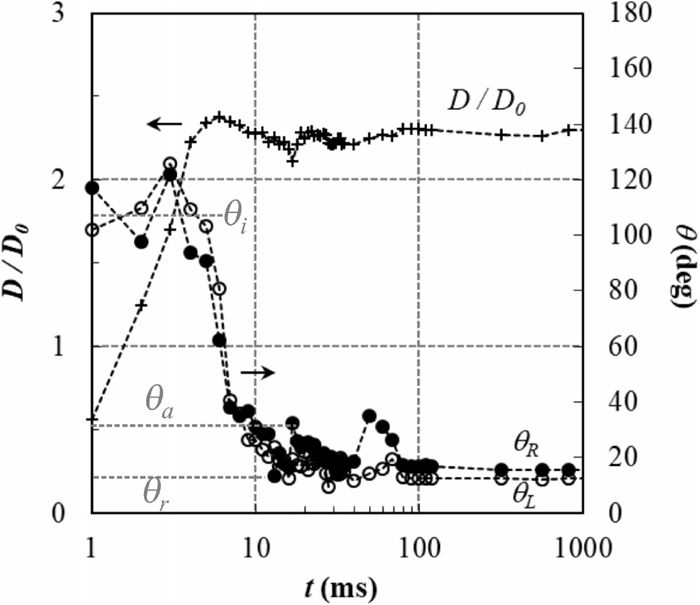
During the first ms of spreading, the contact angle decreases sharply from 180° to a constant value θi and the spreading diameter increases up to its maximum value Dmax. The first measured contact angle is generally less than 180° because the time between two consecutive images (1 ms) is too long to capture the exact moment of the first contact. The contact angle then decreases sharply until it reaches its minimum value after about 10 ms of spreading. During this time, the spreading diameter also decreases, indicating a slight receding of the droplet triple line. After that, both spreading diameter and contact angles increase again. Finally, after approx. 100 ms of oscillations, the contact angle and spreading diameter reach their final values, θf and Df.
The wetting studied here is reactive. Two reactions occur at the interface between steel and liquid Zn/Al alloy: 1) dissolution of iron, and 2) nucleation and growth of an intermetallic compound denoted Fe2Al5Znx (0<x<1).2,3) The preferential dissolution of the solidified droplet makes it possible to observe the interface compound formed under the droplet (top of Fig. 6(a)). At the end of spreading, the surface is covered with small crystals, whose shape is characteristic of Fe2Al5Znx,29) up to the triple line (Fig. 6). An EDS analysis confirms that these small crystals are rich in Al.
Surface roughness measurements of the interface compound were also carried out by means of 3D surface profiler. The average surface roughness Ra obtained is of the order of 180 nm (analyzed surface area of 1.60 × 1.72 mm2).
During the first stage of spreading, until the contact surface of the droplet on the solid substrate reaches its maximum diameter, the wetting of the liquid metal droplet is forced by the initial kinetic energy of the drop. This forced wetting is then followed by a slight dewetting. It can be assumed that the initial contact angle (which is high) corresponds to the contact angle of the solid metal/liquid metal system before the iron dissolution and the formation of the interface alloy begin. In this case, the liquid front at the triple line advances on a flat unreacted surface because the kinetics of spreading is fast compared to that of substrate dissolution. This behavior has already been reported in the literature for the initial instants of spreading in high-temperature dissolutive systems (Cu and Au on Ni)30) and in different steel/liquid Zn systems.7) In addition, the dynamic contact angle is known to increase with increasing triple line velocity for non-reactive wetting,31) which may explain why the initial contact angle is large.
The transition from non-reactive to reactive wetting occurs when the spreading velocity decreases (~ 5 ms). At this point, the mean velocity of the triple line is equal to 0.3 ± 0.1 m s−1. Here, the kinetics of spreading becomes slower than that of the iron dissolution. The droplet receding is essentially prevented by dissolution at the triple line. Finally, the triple line stops (due to iron dissolution) because it stops (when its initial kinetic energy has been completely stored in deformation of the free surface and dissipated by viscosity at the maximum spreading diameter, Section 5.1).
The very short contact times observed for the transition from non-reactive to reactive wetting (~ 10 ms) is in good agreement with theoretical estimations of the galvanizing reaction characteristic times:29) At the moment when the steel surface is put in contact with the liquid metal, the dissolution of iron is the only reaction that occurs at the interface. The concentration of iron increases and exceeds the saturation limit with respect to Fe2Al5Znx. The establishment of the iron supersaturation leading to the Fe2Al5Znx nucleation requires 90 ms, as shown by calculations made for galvanizing conditions similar to those used in our experiments.29) This means that the dynamic contact angle is mainly controlled by iron dissolution up to 100 ms.
The final contact angle corresponds to the contact angle on the intermetallic compound Fe2Al5Znx (Fig. 6). It is of the same order of magnitude as the one obtained on iron. Two reasons can be put forward to explain this: the contact angles of a liquid metal on a solid metal (here Fe) and on an intermetallic compound (here Fe2Al5Znx) are relatively close;1) a receding contact angle is measured throughout the end of spreading due to the contact angle hysteresis caused by an increase in the solid substrate roughness (as a result of Fe dissolution at first and then Fe2Al5Znx formation).
5. Influence of the Initial Kinetic Energy of the Droplet
In our wetting experiments, the impact velocity V0 of the liquid zinc droplet on the annealed substrates varied between 0.7 and 1.6 m s−1. The droplet’s initial kinetic energy Ek given by
is therefore in the range of [2.4.10
−5–1.2.10
−4] J. The relative uncertainty in
Ek is less than 6% (knowing that the uncertainty in
V0 is 0.02 m s
−1).
The main wetting parameters, namely the maximal Dmax and final Df spreading diameters and the initial θi and final θf contact angles, were estimated as a function of the droplet’s initial kinetic energy.
5.1. Spreading Diameter
The maximal and final spreading diameters obtained here are given as a function of the initial kinetic energy of the droplet in Fig. 7. For each trial, Df is the average of the spreading diameter from 100 to 2000 ms. Dmax and Df are increasing functions of kinetic energy, indicating that the liquid zinc drop remains pinned in a metastable position. The final diameter is of the same order of magnitude as the maximal diameter (only slightly lower), which means that the triple line can hardly recede after the first spreading step.
When a droplet is put in contact with a solid, its initial kinetic energy (Eq. (3)) can be dissipated by viscosity or stored in deformation during the impact. Thus, two parameters must be considered to estimate the maximal spreading diameter: the Weber number We which compares inertial and capillary forces and the Reynolds number Re which compares inertial and viscous forces.32,33,34)
|
We=
ρ
Zn
D
0
V
0
2
γ
Zn
| (4) |
|
Re=
ρ
Zn
D
0
V
0
η
Zn
| (5) |
where
γZn is the surface energy (= 810 mJ.m
−2 at 450°C
1,35)) and
ηZn the viscosity of liquid zinc (= 3.41 mPa s at 450°C
23)), the influence of low Al and Fe content in the liquid Zn alloy being ignored. In our wetting experiments,
V0 varied between 0.7 and 1.6 m s
−1. The Weber number is therefore in the range of [13–69] and Re of [4270–9470].
Clanet et al.32) defined an impact number P:
When P < 1 (which is our case), they found that the maximal spreading diameter scales as D0 We1/4.32) This law was interpreted as resulting from the acceleration experienced by the drop during its impact (estimated to be V02/D0). In Fig. 8, the maximum spreading diameters measured for the Zn–Al/steel system were superimposed with the data obtained for water and mercury drops hitting a super-hydrophobic substrate (θ > 160°) and water drops hitting a partially wettable substrate (θa ≈ 90° and θr ≈ 20°).32) All the data were found to collapse on a single curve, when plotting Dmax/D0 as a function of the Weber number. In logarithmic scales, the data are well fitted by a straight line of slope 0.26±0.01:
|
D
max
D
0
=(
0.90±0.04
)
.W
e
(
0.26±0.01
)
| (7) |
The droplet spreading can be limited by capillarity or by viscosity. In the capillary regime, i.e. when the initial kinetic energy of the drop is completely converted into surface energy, the maximal spreading diameter scales as D0 We1/2. The difference we found for the We number exponent (1/4 rather than 1/2) means that a small part of the initial kinetic energy is dissipated by viscosity.34)
5.2. Contact Angle
The initial and final contact angles measured here are given as a function of the initial kinetic energy of the droplet in Fig. 9. For each trial, θi is the average of the left and right contact angles over the range of time they remain constant at the beginning of the spreading. θf is the average of the left and right contact angles from 100 to 2000 ms.
Before commenting on the results, it is important to remember that the contact angle at equilibrium on an ideal surface (i.e., smooth and chemically homogeneous) is unique and given by the Young contact angle at every point of the triple line. For non-ideal solids (i.e., rough and/or chemically heterogeneous), the contact angle is not unique but lies between a minimum receding θr,min and a maximum advancing θa,max contact angle. This is called the contact angle hysteresis.1,27,28)
The initial contact angle is constant and equal to 129 ± 13° in the range of kinetic energy studied. The final contact angle is a decreasing function of kinetic energy, which means that the liquid zinc drop remains pinned in a metastable position, indicating a contact angle hysteresis.
In order to confirm this, the advancing and receding contact angles obtained on the steel surface when the interfacial reactions occur were estimated for all trials. As mentioned in Section 4, the first step of spreading characterized by a high constant contact angle θi corresponds to non-reactive wetting between liquid Zn–Al and steel. The second step of spreading is characterized by a smaller contact angle due to the interfacial reactions leading to the nucleation and growth of an intermetallic compound (Fig. 5). The advancing and receding contact angles were determined at the beginning of this second step, both to the right and left of the droplet: the receding contact angle is the minimum contact angle obtained when the contact angle first decreases. The droplet then advances, leading to an increase in the contact angle. The advancing contact angle was taken at the maximum value obtained before the next droplet receding (Fig. 5). The receding contact angle is constant and equal to 11±5° in the range of kinetic energy studied. This is the minimum receding contact angle. The advancing contact angle measured at the maximum of the first oscillation is a decreasing function of kinetic energy. At the largest kinetic energies, the advancing contact angle cannot reach its maximum value because the drop volume is not sufficient.
The final contact angle lies between the receding and the advancing contact angle (Fig. 9). The final contact angle is of the same order of magnitude as the receding contact angle. The interfacial reactions occurring during spreading almost completely prevent the droplet from receding. The contact angle hysteresis in this case is induced by the interfacial reactivity.
5.3. Forced Wetting
The kinetic energy of the liquid metal droplet needed to reach the minimum receding contact angle can be predicted from the knowledge of the receding contact angle (here θr = 11±5°). The maximal spreading diameter can be used as an order of magnitude of the final spreading diameter calculated with Eq. (7):
|
D
f
≈
D
max
=
D
0
.(
0.90±0.04
)
.W
e
(
0.26±0.01
)
| (8) |
Assuming that the sessile droplet is a spherical cap, the final spreading diameter is linked to the receding contact angle with Eq. (9):
|
m
ρ
Zn
=
π
24
.
2-3cos
θ
r
+
cos
3
θ
r
sin
3
θ
r
D
f
3
| (9) |
The Weber number can be calculated by combining Eqs. (8) and (9). The impact velocity and then the initial kinetic energy of the droplet is deduced from the Weber number (Eqs. (3) and (4)). Taking into account the uncertainty in the receding contact angle, the numerical application for kinetic energy is in the range [1.1.10−4–3.3.10−4] J (impact velocity in the range [1.7–2.1] m s−1). As shown in Fig. 9, this is in good agreement with the experimental points (even if slightly overestimated).
6. Conclusions and Perspectives
In the work presented here, the forced wetting of a partly oxidized steel with a liquid zinc alloy containing 0.18 wt.%Al and 0.01 wt.%Fe was investigated by the dispensed drop method. The fall and spreading of the liquid metal droplet on the steel substrate as a function of the droplet impact velocity were filmed. The film images were used to determine the left and right contact angles and the spreading diameter as a function of spreading time.
During the first ms of spreading, the contact angle remains constant at about 130° and the spreading diameter increases up to its maximal value Dmax. The contact angle then decreases sharply to about 11°, indicating that the wetting is reactive. In the meantime, the spreading diameter slightly decreases. After approx. 100 ms of oscillations, the contact angle and spreading diameter reach their final values.
The maximal and final spreading diameters are increasing in function of the droplet kinetic energy. In good agreement with previous studies in the field of wetting at low temperatures,32) the maximal spreading diameter scales as D0 We1/4, We being the Weber number which compares inertial and capillary forces.
The first step of spreading characterized by a high constant contact angle of 130° corresponds to non-reactive wetting between liquid Zn–Al and steel. The liquid front at the triple line advances on a flat unreacted surface because the kinetics of spreading is fast compared to that of substrate dissolution. The second step of spreading is characterized by a smaller contact angle due to iron dissolution. The kinetics of spreading became lower than that of the iron dissolution. The advancing and receding contact angles were determined at the beginning of this second step. The contact angle hysteresis can be assigned to the triple line pinning at the metastable position due to the beginning of the dissolutive interaction. The final contact angle corresponds to the contact angle on the intermetallic compound Fe2Al5Znx. It lies between the receding and the advancing contact angle and is a decreasing function of the initial kinetic energy of the droplet, which means that the wettability of the steel substrate under study is improved by forced wetting.
The receding contact angle remains constant at about 11°. The kinetic energy of the liquid metal droplet needed to reach this minimum receding contact angle was predicted from the model based on the Weber number to describe Dmax. This kinetic energy is in good agreement with the experimental results.
The final conclusion is how the results of the dispensed drop experiments can provide a better understanding of the galvanizing process, despite the differences between the two configurations. For example, the velocity of the triple line decreases during the dispensed drop experiment while it is constant for the steel strip. The initial impact velocity of the liquid metal drop (0.7–1.6 m s−1) used here is of the same order of magnitude as that of the steel strip (larger than 2 m s−1).2) At such a velocity, our measurements proved that the dissolution reaction does not occur at the triple line. This means that the wetting between steel and liquid zinc alloy is not reactive at the entrance of the bath and is characterized by a high contact angle. Reactive wetting with iron dissolution begins at a distance of approximately 2 mm below the bath surface (strip velocity multiplied by 10 ms corresponding to the transition from non-reactive to reactive wetting).
Forced wetting can also be expected to improve the wettability of steels. However, it remains to be seen how this forced wetting can be achieved in the galvanizing process. Indeed, at the entrance of the bath, the velocity of the steel strip opposes to wetting by liquid zinc whereas the initial kinetic energy of the drop favours wetting (acts in the same direction) in the dispensed drop experiments.
Acknowledgements
The authors are extremely grateful to the staff of CentraleSupélec for their valuable assistance (N. Ruscassier, S. Chen, J. Trubuil). They extend their thanks to Jean-Michel Mataigne for fruitful discussions.
References
- 1) N. Eustathopoulos, M. G. Nicholas and B. Drevet: Wettability at High Temperatures, Pergamon Materials Series, ed. by R. W. Cahn, Elsevier Science, Oxford, UK, (1999).
- 2) A. R. Marder: Prog. Mater. Sci., 45 (2000), 191.
- 3) M. Guttmann: Mater. Sci. Forum, 155–156 (1994), 527.
- 4) Y. Hirose, H. Togawa and J. Sumiya: Tetsu-to-Hagané, 68 (1982), 658.
- 5) Y. Hirose, H. Togawa and J. Sumiya: Tetsu-to-Hagané, 68 (1982), 665.
- 6) L. Bordignon and X. Vanden Eynde: Rev. Métall., 104 (2007), 300.
- 7) Y. Takada, S. Shimada, J. Lee, M. Kurosaki and T. Tanaka: ISIJ Int., 49 (2009), 100.
- 8) S. Frenznick, S. Swaminathan, M. Stratmann and M. Rohwerder: J. Mater. Sci., 45 (2010), 2106.
- 9) J. Lee, J. Park, Y. Kim and S.-H. Jeon: J. Mater. Sci., 45 (2010), 2112.
- 10) T. Kawano and F. U. Renner: ISIJ Int., 51 (2011), 1703.
- 11) T. Kawano and F. U. Renner: Surf. Interface Anal., 44 (2012), 1009.
- 12) M.-L. Giorgi, J. Diawara, S. Chen, A. Koltsov and J.-M. Mataigne: J. Mater. Sci., 47 (2014), 8483.
- 13) P. G. de Gennes, F. Brochard-Wyard and D. Quéré: Capillarity and Wetting Phenomena, Drops, Bubbles, Pearls, Waves, Springer-Verlag, New York, (2004).
- 14) N. J. Ebrill: Ph.D. Thesis, University of Newcastle, Callaghan, Australia, (2000).
- 15) S. D. Aziz and S. Chandra: Int. J. Heat Mass Transf., 43 (2000), 2841.
- 16) Z. W. Chen, R. M. Sharp and J. T. Gregory: Mater. Forum, 14 (1990), 130.
- 17) N. Y. Tang: J. Phase Equilib., 21 (2000), 70.
- 18) M. Zaïdi, M. L. Giorgi, J. B. Guillot and F. Goodwin: Mater. Sci. Eng. A, 495 (2008), 90.
- 19) D. Sonntag: Z. Meteorol., 70 (1990), 340.
- 20) I. Barin and O. Knacke: Thermochemical Properties of Inorganic Substances, Springer-Verlag, Berlin, Verlag Stahleisen, Düsseldorf, (1977), XIII-XIV.
- 21) A. F. Stalder, G. Kulik, D. Sage, L. Barbieri and P. Hoffmann: Colloids Surf. A, 286 (2006), 92.
- 22) W. S. Rasband: ImageJ, U. S. National Institutes of Health, Bethesda, Maryland, USA, (1997-2017), http://rsb.info.nih.gov/ij/, (accessed 2018-01-01).
- 23) L. D. Lucas: Données Physico-chimiques des Principaux Métaux et Métalloïdes, Traité des Matériaux Métalliques, Techniques de l’ingénieur, Paris, (1996), M65:1, (in French).
- 24) A. Ollivier-Leduc, M. L. Giorgi, D. Balloy and J. B. Guillot: Corros. Sci., 52 (2010), 2498.
- 25) E. M. Belhouse and J. R. McDermid: Mater. Sci. Eng. A, 491 (2008), 39.
- 26) I. Olefjord, W. Leijon and U. Jevelstam: Appl. Surf. Sci., 6 (1980), 241.
- 27) W. D. Kaplan, D. Chatain, P. Wynblatt and W. C. Carter: J. Mater. Sci., 48 (2013), 5681.
- 28) D. Quéré: Rep. Prog. Phys., 68 (2005), 2495.
- 29) M.-L. Giorgi, J.-B. Guillot and R. Nicolle: J. Mater. Sci., 40 (2005), 2263.
- 30) E. Saiz, M. Benhassine, J. De Coninck and A. P. Tomsia: Scr. Mater., 62 (2010), 934.
- 31) R. L. Hoffmann: J. Colloid Interface Sci., 50 (1975), 228.
- 32) C. Clanet, C. Béguin, D. Richard and D. Quéré: J. Fluid Mech., 517 (2004), 199.
- 33) M. Pasandideh-Fard, Y. M. Qiao, S. Chandra and J. Mostaghimi: Phys. Fluids, 8 (1996), 650.
- 34) N. Laan, K. G. de Bruin, D. Bartolo, C. Josserand and D. Bonn: Phys. Rev. Appl., 2 (2014), 044018.
- 35) B. J. Keene: Int. Mater. Rev., 38 (1993), 157.


