Abstract
Shape defect such as bow and crossbow, is one of the major defects in hot rolled sheets. These defects arise due to non-uniform plastic strain (thermal and mechanical) due to improper rolling process. In-turn this non-uniform strain induces residual stress in the rolled material. Hence measurement of residual stress in early stage helps as a Go/No Go tool, while supplying material to customers to whom shape defects are very much problematic during its downstream process. In this paper a non-destructive testing (NDT) technique has been developed to predict the magnitude of bow/crossbow based on residual stress measurement using ultrasonic technique. The technique employs the relationship between residual stress distribution and its corresponding effect towards bow/crossbow formation. The paper also elaborates about residual stress measurement using ultrasonic measurement based on the acousto-elastic theory. It was demonstrated that there exists a distinct relationship between crossbow and residual stress for high strength hot rolled steel sheets experimentally.
1. Introduction
Bow and crossbow in flat rolled steel products is one of the major concerns for steel suppliers.1,2) It is an undesirable phenomenon of distortion of flat sheets during processing at customer end. Severity of the problem due to bow/crossbow varies with respect to the application. For instance, it is a severe problem to customers who processes the sheets using laser cutting tools. Since during laser cutting residual stress in the sheets gets released, it leads to distortion of sheets, which in turn damages the expensive laser torch. At such circumstances, the customer rejects the material. This distortion of sheets is a result of residual stress in the material which gets relieved during cutting. Hence it is imperative to develop an NDT technique to predict bow/crossbow in hot/cold rolled sheets, which will assist greatly in decision making in case of a go/no-go situation during coil clearance.
As all manufacturing processes, rolling process also induces residual stress in the hot rolled sheets.3) Hot rolled sheets are produced from slabs, which are processed in hot rolling mills to produce sheets of desired thicknesses. During rolling thickness of the material is reduced as it undergoes plastic deformation as grains are elongated in the rolling direction. As shown in Fig. 1, steel slab is processed in different stages from reheating to coiling during which slab is transformed into sheet.

Non-uniform strain in the material during hot rolling process induces residual stress in the final product.4) Non-uniform rolling and uneven cooling are the main sources for non-uniform strain induced residual stress in hot rolled sheets.5,6) Figure 2 explains bending of rolls causing non-uniform rolling of the material. In such cases, the region which is rolled more will experience compressive residual stress and to counter this compressive stress, the region which is rolled less will experience tensile residual stress. Thus the adverse residual stress is induced during improper rolling processes. Controlling of residual stress to the minimum in the product requires measurement of residual stress at first phase. Hence developing an NDT technique to measure residual stress will help as a feedback tool to control rolling process. However, in this work an ultrasonic based residual stress measurement technique was used to predict shape defects in the product using the relationship between residual stress distribution and shape defects.

Residual stress is the stress that is experienced by the material even when there is no external load acting on it. Stress is measured indirectly as it influences many other physical parameters. Hence various NDT techniques had been developed to measure residual stress since then the problem of residual stress have been realized. X-ray diffraction, neutron diffraction, magnetic barkhausen, Hole drilling method and ultrasonic technique are the widely used techniques for residual stress measurement. In X-ray diffraction technique, inter atomic distance is measured using general X-ray diffraction method, which is then translated to strain. Then residual stress is calculated from the measured strain using stress- strain relationship.7) Though the technique is very sensitive to stress, it is limited to minimal depth of penetration (in the order of microns).8) Unlike other techniques, hole drilling method is a semi destructive technique.8) Magnetic Barkhausen technique is another reliable technique for non-destructive residual technique as it has been demonstrated and for residual stress measurement in weld plates and machined plates, respectively.9,10) The widely used ultrasonic technique also enables residual stress measurement in critical components. Ultrasonic based residual stress measurement technique was used in post heat weld treatment to assess the residual stress in the plates after post heat treatment.11) Ultrasonic based Lcr wave technique was demonstrated as a weld characterization tool.12) Hence, ultrasonic technique and magnetic barkhasuen technique are the reliable and most feasible technique for residual stress measurement in rolled sheets as both the techniques employs portable instrument for testing. Both the techniques were compared in terms of sensitivity and repeatability for residual stress measurement.13) It was reported that the repeatability in ultrasonic technique is higher than magnetic barkhausen technique. Hence in this paper, ultrasonic based residual stress measurement technique (in particular Lcr Wave technique) has been used for predicting bow/crossbow in hot rolled sheets.
2. Theory of Ultrasonic Based Residual Stress Measurement Technique
Conventional ultrasonic technique is used widely for defect detection and thickness measurement of components. In this technique, linear elastic behaviour of ultrasound alone accounted for sound velocity, which is given in Eq. (1) below,
|
V
1
=
E(1-μ)
ρ(1+μ)(1-2μ)
| (1) |
Where,
V1- Longitudinal Wave Velocity (m/s),
E- Young’s Modulus (N/m2),
ρ- Density of Material (Kg/m3),
μ- Poisson’s Ratio.
But non-linear behaviour of ultrasound explains its sensitivity to stress field and it is being utilized for residual stress measurement under acousto-elastic theory.14)
Acousto-elastic theory defines the relationship between the change in sound wave velocity and stress in the same medium. Acousto-elastic constant of a material establishes a relationship between sound velocity and stress as expressed in Eq. (2).15)
Where, V - Velocity of ultrasound in stressed material (m/s),
V0 - Velocity of ultrasound in stress free material (m/s),
σ- Stress (MPa) and B- Acousto-elastic Constant.
There are different modes of ultrasound with respect to the nature of particle vibration and wave propagation direction. Majorly longitudinal, shear wave and Rayleigh wave are the different modes of ultrasound waves. These modes of ultrasound have been studied for its sensitivity to stress field by.16) It was found that critically refracted longitudinal (Lcr) waves are more sensitive to stress field. So Lcr wave was preferred for residual stress measurement in hot rolled sheets.
3. Lcr Probe Design for Residual Stress Measurement
Lcr wave is the longitudinal wave travelling along the surface of the material and they are generated at first critical angle of the material. Refraction phenomenon of ultrasound from perspex to steel is expressed in Eq. (3).
|
sin
θ
p
c
p
=
sin
θ
s
c
s
| (3) |
Where θp is the incident angle, θs is the refracted angle, cp and cs are the longitudinal wave velocity in Perspex and steel respectively. Incident angle is calculated to be 28° for generating Lcr as shown in Fig. 3.
Ultrasonic stress measurement has been simplified further by mounting the ultrasound transmitter and the receiver in a same housing, which enables transit time based stress measurement.15) In transit time based stress measurement, the time of flight of ultrasound from the transmitter to receiver is measured to determine the stress in the material. Hence the equation is transformed as below in Eq. (4),
Where, T – Time of flight of ultrasound in stressed material (s),
T0- Time of flight of ultrasound in stress free sample (s) and B- Acousto elastic constant (s/MPa).
Lcr wave generally travels on the surface and subsurface for limited distance and then it degenerates into bulk waves.17) Hence the distance between transmitter and receiver cannot be maintained to be very high. Hence optimally, transmitter and receiver are kept apart by 50 mm using acrylic block as shown in Fig. 4.
4. Establishing Acousto-Elastic Constant
Bow/crossbow problem is very much experienced in high strength steel (Tensile Strength of 510–630 MPa), hence high strength steel was selected for testing and Table 1 shows the chemical composition in the selected steel grade. A sample of 50 mm width, 10 mm thickness and 350 mm long was stress annealed at 600°C for 3 hours to prepare a stress free sample. Then the sample was mounted with Lcr probe as shown in Fig. 4. Lcr probe attached sample was mounted in a universal tensile testing machine as shown in Fig. 5.
Table 1. Chemical Composition in the steel grade selected for testing.
| Alloying Element | C | Mn | S | P | Si | Al |
|---|
| Weight (%) | 0.06–0.09 | 1.25–1.35 | 0–0.01 | 0–0.025 | 0–0.1 | 0.025–0.05 |
Gradually tensile load was increased and at regular stress interval (10 MPa) the ultrasonic signal was analysed for transit time measurement. Then the transit time was plotted against corresponding stress level as shown in Fig. 6. From the slope of the linear relationship between stress and transit time, acousto elastic constant is determined as 0.3 ns/MPa. The developed acousto-elastic constant is specific to the grade of material and Lcr probe.18)
5. Relationship between Residual Stress and Crossbow Formation
Prediction of bow/crossbow is aimed based on the relationship between residual stress and its corresponding effect on bow/crossbow formation during further processing. Crossbow formation in HR sheets during further processing at customer end happens as a consequence of release of residual stresses. After crossbow formation the material redistributes the remaining residual stress within the material. Hence the sample was measured for residual stress distribution in terms of differential residual stress as shown in Fig. 7. Differential residual stress is measured as the difference between maximum and minimum residual stress in the sample as it was measured in different locations along the width.

Samples of the same grade were collected from different parts of the coil, i.e. head, middle and tail portion of the coil. As shown in Fig. 8 full width samples of 1 m long were tested for residual stress using ultrasonic probe at three locations along the width (Centre and Edges). Differential stress which represents the residual stress distribution in a sample is calculated as the difference between maximum and minimum residual stress measured along the width. Figure 9 portrays the actual measurement in the sample.

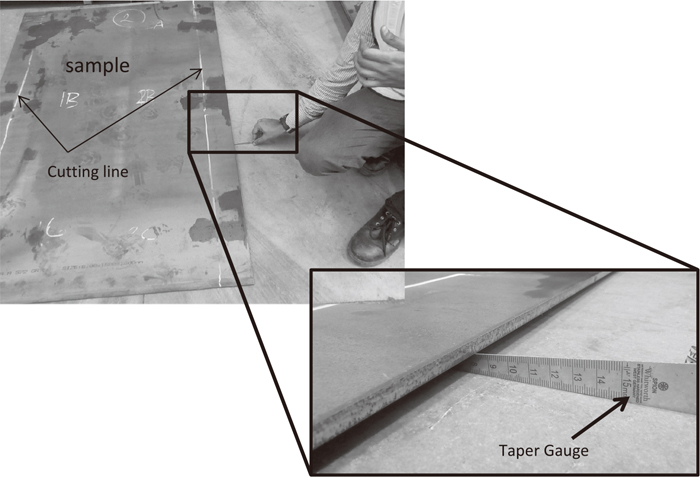
The samples were measured for initial bow using taper gauges as shown in Fig. 10. Then sample was cut along the line shown in Fig. 10 by a shear cutting machine (any effect due to cutting process will be same for all samples). Then the sample was again measured for crossbow. Final crossbow was observed to be greater as the residual stress in the sample got relieved during cutting. Difference between initial and final crossbow, is measured as the actual crossbow in the sample due to residual stress. The test was carried out for 10 no. of samples.
6. Results and Discussion
Results of the above experiment are plotted as shown in Fig. 11. It shows a good relationship between crossbow and residual stress. As stated, when the sample is cut some of the residual stress in the sample gets relieved as it causes crossbow formation and the remaining stress gets redistributed as it causes cross. So after cutting, the sample gets reduced residual stress or new distribution of stress.19) For experimental verification of this phenomenon, two cut samples were taken for measurement of differential residual stress and compared with the stress values before and after. Differential residual stress in the cut samples is observed to be lessened after cutting as given in Table 2. This proves that the established relationship shown in Fig. 11 can be used as an NDT tool to predict crossbow in HR sheets, which will help in Go/No Go decision making while supplying materials to critical customers. Also the same curve can be used to assess the rolled products in terms of residual stress in it, which will be used as a feedback tool to assess and optimize the process parameters. The relationship shown in Fig. 11 tends to vary with respect to the width of the strip cut and thickness of the sheet; hence the strip width should be decided as per the application.

Table 2. Redistribution of residual stress after cutting the sample.
| S.No. | Differential residual stress measured using the developed Lcr probe (MPa) | Crossbow measured using Taper gauge (mm) |
|---|
| Before Cutting | After Cutting | Before Cutting (B) | After Cutting (A) | Net crossbow (B-A) |
|---|
| 1 | 266.66 | 140 | 5 | 27 | 22 |
| 2 | 146.66 | 66.66 | 1.5 | 17 | 15.5 |
Though Fig. 11 shows a good relationship between residual stress and crossbow, there are some deviations also being observed. These deviations can be reduced by increasing no. of measurement along the width of the sample (currently three no. of measurements are taken). Hence the above relationship can be refined further and can be used as a crossbow prediction tool for HR sheets.
7. Conclusion
An NDT technique based on Lcr waves has been developed for predicting bow/crossbow formation in hot rolled coils. In the technique, differential residual stress is measured using Lcr probe, and then the measured stress was correlated with crossbow formation in the sample. As expected a distinct relationship between differential residual stress and crossbow was observed as shown in Fig. 11. Using this relationship and Lcr probe, prediction of bow/crossbow in any unknown can be done. Hence Lcr wave ultrasonic technique can be used to help in Go/No Go decision making while supplying materials to customers to whom bow/crossbow is critical. The overall crossbow prediction using this technique can be refined further by increasing the number of samples and more measurements along the width of the sample.
Acknowledgements
The authors are very much thankful to the management of Tata Steel, particularly to R&D and Flat Product Technology Group, for their valuable support and encouragement throughout this work.
References
- 1) R. Cols, L. Adolfo, L. Lezma and M. Neri: Ironmaking Steelmaking, 31 (2004), 93.
- 2) T. Masui, Y. Kaseda and K. Ando: ISIJ Int., 31 (1991), 262.
- 3) G. Totten, M. Howes and T. Inoue: Handbook of Residual Stress and Deformation of Steel, ASM International, Materials Park, OH, (2002), 11.
- 4) P. J. Withers: Rep. Prog. Phys., 70 (2007), 2211.
- 5) Z. Zhou, P. F. Thomson, Y. C. Lam and D. D. W. Yuen: J. Mater. Process. Technol., 133 (2003), 184.
- 6) W. Razny, F. D. Fischer, G. Finstermann, W. Schwenzfeier and K. Zeman: J. Mater. Process. Technol., 60 (1996), 81.
- 7) S. Tanaka and Y. Takahashi: ISIJ Int., 30 (1990), 1086.
- 8) C. O. Ruud, P. S. Di Mascio and J. J. Yavlek: Exp. Mech., 25 (1985), 338.
- 9) H. I. Yelbay, I. Camb and C. H. Gura: NDT&E Int., 43 (2010), 29.
- 10) L. Mierczak, D. C. Jiles and G. Fantoni: IEEE Trans. Magn., 47 (2011), 459.
- 11) D. E. Bray and P. Junghans: NDT&E Int., 28 (1995), 235.
- 12) M. Vasudevan, R. Shanmugasundaram, B. Arivazhagan, P. Vasantharaja and P. Palanichamy: Mater. Eval., 72 (2014), 1509.
- 13) P. Pereira, F. Armando and A. A. Santos: J. Strain Anal., 51 (2016), 563.
- 14) D. S. Hughes and J. L. Kelly: Phys. Rev., 92 (1953), 1145.
- 15) P. Palanichamy and M. Vasudevan: J. Pure Appl. Ultrason., 32 (2010), 101.
- 16) D. E. Bray: 15th World Conf. on Non-Destructive Testing, AIPnD, Brescia, (2000), 15.
- 17) K. J. Langenberg, P. Fellinger and R. Marklein: Res. Nondestruct. Eval., 2 (1990), 59.
- 18) H. Qozam, S. Chaki, G. Bourse, C. Robin, H. Walaszek and P. Bouteille: Exp. Mech., 50 (2010), 179.
- 19) P. Dong, P. Cahill, Z. Yang, X. L. Chen and N. J. Mattei: J. Ship Prod. Des., 20 (2004), 245.