Casting and Solidification
Advances in Ladle Shroud as A Functional Device in Tundish Metallurgy: A Review
2019 Volume 59 Issue 7 Pages 1167-1177

Details
2019 Volume 59 Issue 7 Pages 1167-1177
Ladle shroud is a small but significant device in tundish metallurgy to facilitate both production process and steel quality. Past decades have witnessed its evolution from a simply shrouding tube to a multi-functional device in continuous casting processes. Advances in the functions of ladle shroud in tundish metallurgy have been reviewed in this work, including shrouding the teeming stream, fluid flow control, slag carry-over detection, and the potentials of heating and additive feeding. The features of various commercialized and novel ladle shrouds are discussed. The effect of practical operations, such as argon injection and misalignment, on the performance of ladle shrouds is also analyzed in this review.
The worldwide steel yield reached 1689 million tons in 2017,1) the continuously-cast output of which accounted for 96.3% owing to the soundness of high efficiency and cost-effectiveness of the continuous casting (CC) process. Tundish is the last vessel before the solidification in the mold, and quality of molten steel should be supplied in terms of composition, temperature and cleanness at a desired casting speed.2,3,4,5,6)
Ladle shroud (also called long nozzle, shrouding pipe or pouring tube2)) is a refractory tube used to transfer molten steel from ladle to tundish. It is a small device in the whole CC process but plays an important role in tundish metallurgy. The invention of the ladle shroud derived from the requirement to shield the teeming stream from atmospheric contamination.7,8,9,10) In the initial developing stage of the CC process, re-oxidation and air-pickup were found to be important reasons for the formation of macro inclusions, which resulted in a series of quality issues.9) The application of ladle shroud achieved great success in shrouding the melt stream. An early trial conducted in Steelmaking Burns Harbor Slab Plant (Indiana, USA) documented7) that the average oxygen content decreased around 50% by using a ladle shroud made of fused silica. The average life of the silica ladle shroud was only 2.5 heats. Modern ladle shrouds can serve for tens of heats with the help of upgraded alumina-graphite composites, structural design and coating technology. The shrouding effect has been optimized to minimize the air ingress by using argon injection and proper sealing/holding technologies.11)
The performance of tundish metallurgy is closely related to the flow characteristics of molten steel.3) In recent years, ladle shroud has been proposed to be potential to control the entry flow of the tundish so as to optimize the flow pattern inside the whole tundish.12,13,14,15) The turbulence kinetic energy is high inside the ladle shroud and the velocity can reach up to several m/s. As a result, the jet flow of ladle shroud largely determines the flow pattern in the pouring zone and consequently influences the whole flow field of the tundish. Several novel ladle shroud designs have been developed for this purpose, such as trumpet-shaped ladle shroud (TLS),16,17,18) swirling ladle shroud (SLS)12,13,19,20) and dissipative ladle shroud (DLS),14,15,21) which outperformed the conventional ladle shroud (CLS) in terms of flow control. In particular, the TLS has been practiced owing to its ease of manufacturing and various metallurgical benefits.
However, challenges remain and new ones appear. There have been mainly three driving factors for the advances of ladle shroud: maximizing the shrouding effect from air ingress, exploring multiple functions and solving newly arisen issues. For example, the vibrational signal from the ladle shroud has been used to detect the ladle slag carry-over.22) As recent technological advances in steelmaking practices, there is a continuous demand for the development of ladle shrouds for higher production efficiency, better steel quality and longer service life. The main thrust of the current work is to overview the advances in the development of ladle shroud and its functions in tundish metallurgy. Emphasis is placed on the development and optimization of ladle shrouds by looking at their structural and operational performances.
Figure 1 schematically shows the main metallurgical behaviors in a modern steelmaking tundish during the CC process. Detailed flow control devices at the bottom of a ladle are illustrated in Fig. 2, including well block, slide gate, joint nozzles, gasket, argon port and ladle shroud. These parts are used to connect the flow stream from the ladle bottom to the tundish pool. A well block seats at the bottom of a ladle with a bore to discharge the molten steel and adapts an upper nozzle. The control of flow rate is realized by a stopper inside the ladle or an external slide gate. The slide gate arrangements have currently been used dominantly due to its ease of maintenance and repairing. As shown in Fig. 2, a movable nozzle (lower nozzle or collector nozzle) is aligned together with a stationary nozzle (upper nozzle) on the bottom of the ladle.23) The opening or closing of the slide gate is driven by a hydraulic device. The lower nozzle sits on the bowl-shaped upper end of a ladle shroud. Argon is usually injected from a gas port to shield the stream and encourage the clean steel production. The ladle shroud is held and moved using a hydraulic manipulator.
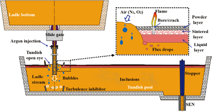
Main metallurgical behaviors in a steelmaking tundish during continuous casting. (Online version in color.)
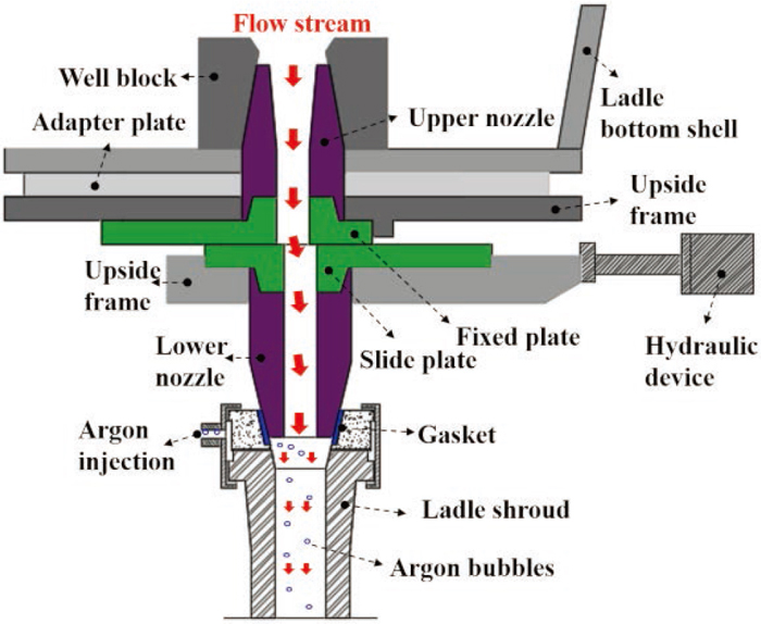
A schematic drawing of the flow control system at the bottom of a ladle. (Online version in color.)
When the melt-argon plume enters the tundish pool, the melt goes down while the argon bubbles tend to rise. A turbulence inhibitor is usually used to suppress the incoming jet and relief the surface fluctuation. The emission of argon bubbles may sweep off the tundish slag and thus forms a tundish open eye (TOE). It was reported that the TOE could bring about dire consequences, such as radiative heat losses, reoxidation of the liquid steel, nitrogen pickup.24) The tundish slag typically comprises three layers: a liquid layer, a sintered layer and a powder layer from bottom to top. The sintered layer is inherently featured with many cracks or pores, and eruption of flames can be observed due to the emission of combustible gases (e.g. CO). The jet flow of the ladle shroud features strong turbulence and largely determines the flow pattern of the pouring zone, which directly influences the formation of TOE, tundish surface fluctuation, refractory erosion and trajectories of argon bubbles. Thus, ladle shroud is of significance to the performance of tundish metallurgy.
The most prior and important function of the ladle shroud is shrouding steel stream from being exposed to open air and tundish slag which can lead to reoxidation, gas pick-up and slag entrapment. The following sections will firstly describe the documented contaminations from air/slag and then outline related techniques to tackle them.
3.1. Atmospheric Contamination of the Teeming StreamThe extensive applications of continuous casting in steelmaking industry began in 1970s. Reoxidation and gas pick-up of teeming stream from the ladle to the tundish were noticed at the initial developing stage. Little et al.9) were among the earliest authors who systematically reported the reoxidation of molten steel teemed through air. They observed the appearances of ladle streams using common and high-speed cinephotography, and several modified photos of the ladle stream are shown in Fig. 3. Figure 3(a) displays a visual observation of the rough ladle stream and splashing. Figure 3(b) illustrates the discontinuous nature of the ladle stream under a high-speed camera at a filming speed of 2000 frames per second. When the stream was teemed from the ladle, a continuous supply of air was carried down into the tundish pool. The ladle streams appeared to be rough and discontinuous in an irregular shape, which intensified the splashing, fume and turbulence in the tundish pool. These behaviors are also largely related to the air pick-up, reoxidation and even slag entrapment inside the tundish. To have a better understanding of these issues, water-model studies were carried out to investigate the tundish and mold flow conditions with or without a ladle shroud.9) The shrouded liquid surface was changed from “rough” to “calm”, liquid vortices from “many” to “moderate”, particle distribution from “very dispersed” to “confined”, which were claimed to be able to reduce the likelihood of slag entrapment both in the tundish and the mold. In addition, levitated droplets of steel was deoxidized and then exposed to oxidizing atmosphere to study the type of reoxidation products formed during non-shrouded teeming.9) It was found that the oxidized products matched the observed nonmetallic inclusion observed from the subsurface defects in continuously cast slabs. These observations adequately confirmed the existence and adverse effects of the contamination on non-shrouded teeming stream.
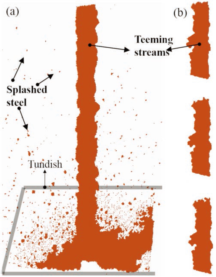
Modified appearances of the non-shrouded ladle stream from Little et al.’s work.9) (a) Visual observation of the rough ladle stream, and splashing; (b) discontinuous ladle stream appearance, 5 minutes after the start of teeming using a high-speed camera at a filming speed of 2000 frames per second. (Online version in color.)
In the following years, the evidence of gas entrainments and reoxidation were frequently confirmed and the hazards were reported on both experimental and industry scales.7,25,26) A representative investigation was carried out by Ohno et al.10) to quantify large non-metallic inclusions in continuously cast Al–Si killed steel. They found that the amount of large inclusions increased by a factor of 2.5 between the ladle and the tundish caused by the reoxidation of the ladle stream. Moreover, the reoxidation represented 40% contribution among a variety of factors that brought about inclusions to the molten steel.
Attentions were also paid to develop models to quantitatively evaluate the rate of atmospheric reoxidation and gas entrainment into the teaming steel.8,26) The governing factors were recognized to be the shape of the nozzle, height of the teeming, the depth and the flow of molten steel in the ladle, stream turbulence, and physico-chemical properties of molten steel (e.g. viscosity and surface tension).
3.2. Initial Techniques to Shield the Teeming StreamApart from the work to confirm and quantify the contamination from the open air, it is more valuable to develop techniques to overcome these problems. There were initially two ways to shield the stream during this transfer. One is gas shrouding, namely using inert gas (mostly argon) to envelop the teeming flow and isolate it from the air. The other one is mechanical shrouding, i.e., utilizing a refractory ladle shroud to connect the flow between the ladle and the tundish.
The gas shrouding is effective in containing the streaming and reducing the reoxidation.2) However, the absorption of argon into steel could occur, and cost is high because the consumption of argon used in the shrouding was considerable. Furthermore, if ladle slag is carried over in the shrouding gas, the impinging melt stream from the ladle will emulsify the slag into the melt and forms macro inclusions.2) As a consequence, the gas shrouding failed to find wide uses.
Compared with the gas shrouding, the ladle shroud envelopes the teeming stream using a refractory tube to form a straight flow channel. An early attempt to examine the effect of a set of ladle shrouds was carried out in Steelmaking Burns Harbor Slab Plant in 1978.7) A 48-inch long open-bottom tube, made of fused silica, was firstly tested, and then was lengthened to 66 inches to submerge into the tundish pool. The ladle shroud was found to be highly successful in containing the stream and reducing reoxidation. The average oxygen content decreased from 40–45 ppm to 20–25 ppm; surface quality of the cold rolled sheet from the cleaner shrouded steel was far superior to non-shrouded steel and the direct charge slab quality rose from 85% to 97%.7)
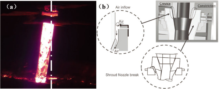
3.3. Techniques to Optimize the Shrouding Effect 3.3.1. Fundamental of Air Ingress into Ladle ShroudThe invention and use of a ladle shroud broke a new path to protect the molten stream from atmospheric contamination during teeming, but they had not completely eliminated the issue. The teeming stream seems to be mechanically isolated from the ambient air by using a ladle shroud. However, air can still trickily get in any opening under any faint forces. A possible opening is the junction crevices between the collector nozzle and the ladle shroud because of the challenges to achieve seamless sealing. A schematic drawing of the air ingress is shown in Fig. 4, where the incoming mass of the ladle stream is Qm1, and Qm2 is the absorbed air mass at a pressure P2. The mixture of air and molten steel (Qm3) flows through the ladle shroud at P3. An equation was deduced to evaluate the gas absorption rate based on the momentum conservation, and the air absorption rate from the crevices can be expressed as:11)
| (1) |
| (2) |
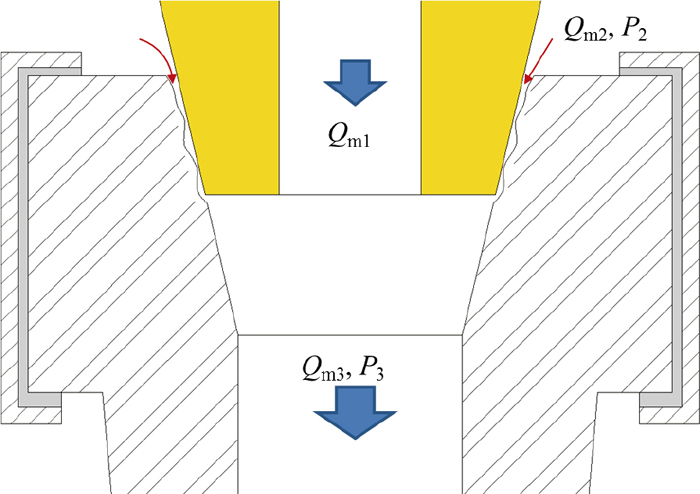
A schematic drawing of the air ingress from the crevice of the ladle shroud. (Online version in color.)
This equation implies that a larger flow rate can bring about a higher maximum pressure difference. As the casting speed has been at an increasing tendency, a better sealing technique is required to bear the pressure difference. Considering the deduced equation and the shrouding mechanism, three strategies can be proposed to minimize the air ingress:11) (1) injecting inert gas into the ladle shroud to reduce the pressure difference; (2) argon curtain sealing to replace the absorbed air by argon; and (3) improving the junction to enhance the sealing.
3.3.2. Ladle Shroud with Argon Injection and GasketIn CC practices, the gas shrouding and mechanical shrouding have been usually combined, that is injecting argon into a ladle shroud to improve the shrouding performance. Argon can be injected from the shroud neck as shown in Fig. 5(a), which has been widely used. An argon curtain is fixed around the head of the shroud in Fig. 5(b). A soft gasket is introduced to better the junction (Fig. 5(c)). In most cases, two or three of them have been adopted together to achieve optimized effects, as shown in Fig. 6. A small gasket is commonly used between the ladle shroud and the collector nozzle. The gasket is usually in annulus or frustum shape, made of either plaster or refractory materials added with ceramic fibers.
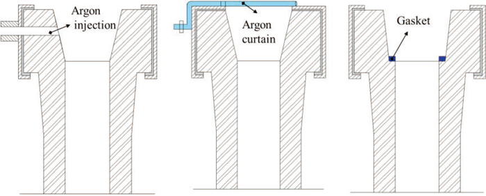
Three types of technique to protect the ladle stream from air ingress. (a) Argon injection; (b) argon curtain sealing; and (c) gasket sealing. (Online version in color.)
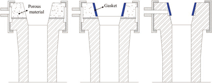
Typical combination of multiple techniques to optimise the shrouding effect. (Online version in color.)
It should also be mentioned that the shrouding performance is also closely dependent on the operational conditions. The misalignment of a ladle shroud has been frequently observed (as typically shown in Fig. 7) due to the difficulties to position the heavy equipments and the limitation of holding technology.27) When the lower nozzle and the ladle shroud are not aligned, the airtight condition becomes poor which brings about air infiltration as shown in Fig. 7(b).28) Meanwhile, the gasket tends to be damaged under concentrated forces when the nozzle is not well positioned.11) Thus, it is necessary to enhance the control accuracy of the ladle and the ladle shroud manipulator to ensure a good connection. More remedial methods for the misalignment will be discussed in section 4.3.
The failure of a ladle shroud subjects the molten steel to total exposure, and may cause safety issues. Thermal stress, mechnical forces, decarbonrization, erosion from the steel and the slag are the main contributing reasons for the breakdown of the shroud.29) The initial ladle shroud was made of silica, and it could only last for nearly two heats.7) The modern ladle shrouds are well developed with respect to materials and structural designs. They are commonly made of alumina-graphite composites and coated with anti-erosion lining materials, such as ZrO2 and carbon-free inside liner composites.30,31,32,33,34,35) The working life has now been extended to tens of heats36) thanks to typical techniques, such as inner and outer layer lining,31,33) additive strengthening,37,38,39) thickness adjustment40) and cleaning technology.41) Some typical techniques to improve the performance of ladle shrouds are described in Table 1 in terms of materials design, lining and maintanence.
| Techniques | Improved properties and contributing mechanisms | Remarks |
|---|---|---|
| ZrO2 around the slag line35) | ZrO2 reacts with tundish slag and form a layer to prevent the penetration of slag, improving the corrosion resistance. | Commercialized, good performance to resist the erosion of slag. |
| Inner free-carbon lining33) | 1) The carbon-free liner acts as a heat insulator reducing thermal shock 2) Reducing thermal stress at the point of contact | A commercialized technique working on the inner wall. |
| Foaming coat of outer surface36) | Coating at the outer surface with materials with good performance in splash resistance and insulating heat | A commercialized technique; long serving life (>40 heats). |
| Ladle shroud with high tension and toughness82) | 1) High tensile strength by reinforcing the carbon bonding; 2) Uniform strength by distributing grains and binders evenly; 3) Low elasticity by optimising grain size and distribution. | Requiring good manufacturing and processing to produce ladle shroud. |
| Metallic additive (Al, Si)39) | Reducing CO to C, suppressing oxidation loss of carbon | Under exploration, promising. |
| Nano additives (carbon nanotube, MgAl2O4, Al2O3)38) | Improving strength and thermal shock performance by reinforcing the binder matrix with the homogeneous distribution of the nanoscaled spinel additives. | Under exploration; requiring well distribution of nano materials; high cost. |
| Increasing the wall thickness in the submerged part40) | The submerged section is subjected to slag erosion and easy to be destroyed. | A traditional strategy. |
| Shower cleaner41) | Replacing point cleaning with face cleaning during ladle changeover time, which is safer and no splash to increase service life. | Simple and cost-effective. |
The performance of a tundish has a close relationship with the flow characteristics of molten steel. A well-known and traditional way to control the fluid flow is designing flow control devices (FCDs) inside a tundish, such as turbulence inhibitor, weir and dam.3,42) Alternatively, it is a new concept to employ the ladle shroud to perform flow control on the entry jet of the tundish with the purpose of controlling the fluid flow in the whole tundish. As the trend of steelmaking industry is to simplify operations and decrease costs while maintain or even increase steel quality, ladle shrouds have the potential to replace the FCDs mentioned above. From the standpoint of fluid dynamics, the flow pattern is mainly determined by the geometrical design of the ladle shroud and the casting operations (e.g. submergence depth). They are also the foci of interest in this section.
4.1. Industrialized Ladle ShroudsThere are currently two kinds of industrialized ladle shrouds in modern CC practices, as shown in Fig. 8. One is the initial CLS, featured with a straight inner bore. The other one is called trumpet-shaped ladle shroud (TLS, also mute or bell-shaped ladle shroud), which has a trumpet outlet with an enlarged bore. Two types of TLSs prevail in the market, with either a gradually enlarged trumpet (type-1) or a divergent chamber and a straight end with a larger diameter (type-2). The documented benefits of TLS are manifold and summarized in Table 2. The TLS was suggested in industry and showed its merits in terms of production efficiency and molten steel quality. Compared with the CLS, the TLS was demonstrated to be able to decrease the rate of nozzle clogging,16,17,43) and eliminate flow backs during a ladle change or first tundish filling operation,43,44) thereby reducing the frequency of operation disruptions and enhancing the production efficiency. Simultaneously, the TLS is capable of improving flow characteristics in a tundish,45) minimizing turbulence in the pouring zone17) and eliminating slag entrapment,16,46) so as to improve the steel cleanness.18) When the outlet diameter of the ladle shroud is increased, the jet velocity is dramatically decreased to weaken the turbulence both in the ladle shroud and the pouring zone of a tundish.47,48) This is also favorable to eliminate lining erosion and enlarge the plug volume.
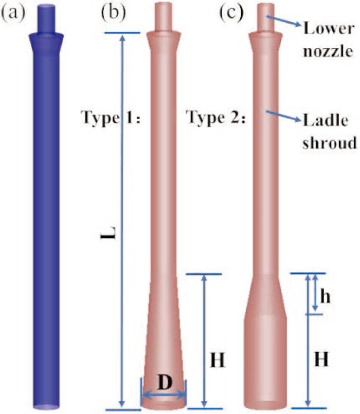
Illustrations of the (a) CLS, (b) type-1 TLS and (c) type-2 TLS. (Online version in color.)
| Authors/year | Main benefits of the TLS |
|---|---|
| B. Becker et al./199116) | Decreased clogging rate and improved producing efficiency. Less folding in cold rolling process at No. 2 BOF/CC of Inland Steel, combined with a steel sheet cover at the end of the TLS. |
| B. G. Thomas et al./200117) | Maintaining minimal turbulence during tundish filling. |
| L. Zhang et al./200318) | Lower T.O contents were observed inside the tundish for 300 heats. |
| G. Solorio-Díaz et al./200413) | The tip of the shroud has bell shape to reinforce the braking effect on the fluid which flows into the tundish. |
| M. Nadif et al./200746) | Permitting safe submerged opening with bell-shaped. Preventing the generation and entrapment in products of emulsified steel-slag mix. |
| K. Chattopadhyay/201144) | Eliminating flow backs during a submerged ladle change operation. Accommodating for hot gas pockets. |
| G. Wen et al./201145) | Decreasing shortcut flow volume; elongating residence time and improving mixing in physical experiments. |
| J. Wu et al./201343) | Weakening the back flow inside the ladle shroud during the tundish filling. |
| J. Zhang et al./201847,48) | Relieved impact and steel splashing during ladle opening. A calm tundish bath was achieved using the TLS. |
As a case study, the authors [50] carried out trials to comparatively investigate the effect of a CLS and a TLS on the multiphase flow of a tundish. These two ladle shrouds were fixed on the same ladle and delivered steel melt into two 25 t independent tundishes. Detailed casting parameters were listed in Ref.48) During transient operations (e.g. ladle change), steel splashing may occur due to the non-immersion ladle opening or the intense impact between teeming stream and the low-level tundish pool. The splashing indicates the exposure of tundish melt, intense steel-slag emulsification and possible slag entrapment. Typical photos of splashed sparks are shown in Figs. 9(a) and 9(b). The number of splashed sparks on top of the tundish bath were recorded during ladle opening and descending as shown in Fig. 9(c). It was noted that the observed sparks by using the CLS always outnumbered those by using the TLS in the 10 s of descending, which implies the effect of the TLS on alleviating impaction and protecting the melt. During steady casting, a calm tundish bath and well covered flux were achieved by using the TLS, as shown in Fig. 9(d). While, an eccentric tundish open eye and waving flux with flames were observed around the CLS as shown in Fig. 9(e), which indicates fluctuating tundish bath in the pouring region.48) Therefore, the TLS outperformed the CLS in protecting the steel melt during both the transient and steady casting. It should be mentioned that these significant differences are also associated with the volume of the tundish bath. In modern CC process, the tundish with 25 tons capacity can be categorized into a small one. The tundish capacity has been increased to around 100 tons.2) The effect of different ladle shrouds on large and deep tundish pools might be different, which needs to be considered in the future studies.
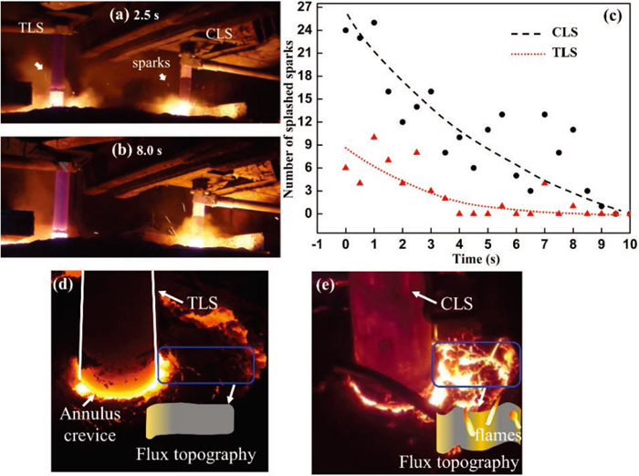
Snapshots of splashing and smoking above the tundish at (a) 2.5 s and (b) 8.0 s after ladle descending. (c) The recorded number of splashes in the shooting range and fitted curves. The actual and schematic topographies of tundish flux using the two ladle shrouds during steady casting: (d) TLS and (e) CLS. (Online version in color.)
Considering the effects of the ladle shroud to control fluid flow and requirements of special-structured tundishes (such as asymmetrical tundishes), endeavors have been paid on the development of novel ladle shrouds, which are schematically shown in Fig. 10. Their main features were briefly summarized in our previous work.15)
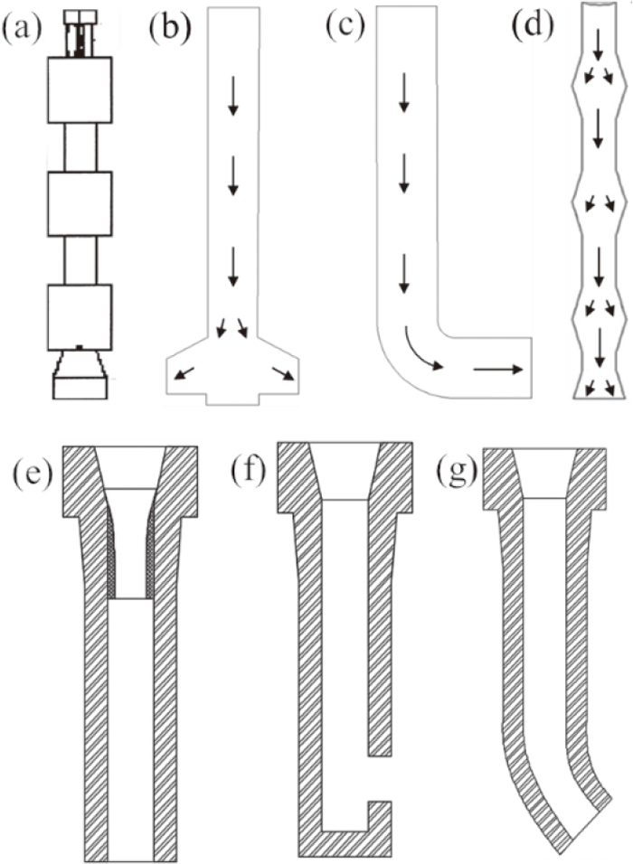
Various new ladle shrouds under exploration. (a) swirling ladle shroud (SLS), (b) two-side ports ladle shrouds, (c) a bending nozzle, (d) dissipative ladle shroud (DLS), (e) ladle shroud with a regulating tube, (f) and (g) biased ladle shrouds.
Morales et al.12,13,19,20) proposed the concept to use ladle shrouds to control the fluid flow inside a tundish and developed a SLS at a laboratory scale. The SLS has a blade, three chambers and a bell tip to promote a swirling flow and dissipate kinetic energy inside the SLS. Their experiments showed that recirculatory flows were generated and the liquid surface tended to be quiet. The flow parameters were able to improve inclusion floatation. These effects are very similar to other FCDs used inside a tundish, and thereby being potential to be replaced by the SLS. However, the industrial version of the SLS should firstly tackle the issues of manufacturing full-scale mechanisms for practical applications and the erosion of the refractory tube and blade under high turbulence.
A bending nozzle49) was invented to encourage the swirling velocity in the rotation chamber of a centrifugal tundish, which was expected to benefit the inclusion collision and floatation. The effects of the bending nozzle were quite positive in the special-structured tundish. However, it should be noted that stresses can be concentrated on the bending zone to cause erosion; biased forces are exerted on the joint between the collector nozzle and the bending nozzle, which could lead to the formation of crevices and gas ingression. Similar issues also apply to the biased ladle shrouds,50) as the shape of the shroud was asymmetrical.
A regulating tube51) was suggested to be equipped around the neck of the ladle shroud to regulate the steel flow and work as a heat buffer layer to relieve the thermal stress and cracking. The materials of the regulator should be specialized to ensure a good connection to the inner layer of the ladle shroud and highly resistant to flow erosion.
Chatterjee52) brought forward a two-side-port ladle shroud, which seems like a submerged entry nozzle used in the mold. It was experimentally effective to supply molten steel at a slow rate to avoid turbulence, emulsification and the formation of TOE in the tundish. Nevertheless, there should be enough space and fluid to buffer the entry stream in the tundish. Otherwise, the lining of tundish walls can be seriously eroded. Thus, this ladle shroud can probably find uses in symmetric multi-strand tundishes, such as two-strand and four-strand tundishes, which usually have sufficient space around the ladle shroud.
A newly-developed ladle shroud was called dissipative ladle shroud (DLS), featured with three diamond-shaped chambers and a bell outlet. Morales-Higa et al.14) proposed a DLS and demonstrated that the DLS radically decreases the entry velocity and dissipated kinetic energy of the flow. Transient jet deformation flows were developed, and their frequency of oscillation was increased at increased flow rates. A comparative investigation was carried out to study the flow structure and inclusion removal in a SLS, a DLS and different tundish arrangements.21) The three chambers encouraged the fluid mixing and deformation rate, promoting the turbulence dissipation and the decrease of velocity. The authors15) employed large eddy simulation (LES) to investigate the flow structure in a DLS and a tundish model, compared to that in a TLS. It was demonstrated that the turbulence kinetic energy was largely dissipated in the chambers and the outlet velocity was decreased. However, the actual application of the DLS is still dubious. The manufacture of the internal shape even with isostatic pressing would be complex, although a form of three-piece tool could be constructed. The thermal gradients between the thick and thin areas in the shroud stock could cause problems.
Most of the abovementioned new ladle shrouds were just confined in laboratory studies using mathematical/hydrodynamic modelling. Although, favorable flow characteristics were obtained, trials and industrial applications are highly encouraged to examine the practical performance.
4.3. Ladle Shroud Operation 4.3.1. Argon InjectionArgon injection not only offers effective shrouding benefits to the ladle stream as mentioned above, but also influences the multiphase flow. To have a good insight into the injected argon, attentions were paid on the basic behaviors of argon bubbles, including bubble size, bubble trajectories, and their influences on other fluids (e.g. tundish slag).
(1) Formation of Fine Bubbles
Fine bubbles are desirable for inclusion removal and large bubbles may result in churn-turbulent flow, reducing the collision efficiency inside the shroud due to bubble coalescence.53) The flow structure inside a ladle shroud is characterized with high shear rates and turbulence kinetic energy, which makes it an ideal place to form fine bubbles.54) The bubble size has been found to be associated with the gas inlet diameter, liquid properties, relative flow rates of argon and steel etc.55,56,57,58) Related studies are summarized in Table 3. For example, Guthrie et al.54) demonstrated that fine bubbles (<1.0 mm) can be formed when the water speed is high and the air rate is low. Similarly, Chattopadhyay et al.57,59,60,61) found that the average bubble size at lower flow rates of 2 to 4 pct (the ratio to steel entry flows) was 3.7 mm; whereas, the average bubble size was 5.0 mm at higher flow rates. These mean that the higher flow rate of argon promotes the growth of larger gas bubbles. Tang and Bao et al.55,56) evaluated the maximum bubble size in argon-water and argon-molten steel systems. It was predicted that when the flow rates were 0.006–0.016 m3/s, the maximum sizes of the bubbles in the water and steel flow reached 0.70–1.44 mm and 1.53–3.16 mm respectively. Besides theoretical analysis, mathematical and physical modellings are resorted frequently to characterize the bubbles. The study of Wang et al.58) showed that fine bubbles smaller than 0.5 mm could be created and had a good mixing with the liquid due to the breaking up by the high turbulence flow in the ladle shroud. The opening of slide gate was considered and the range of bubble size was measured to be 0.3–8 mm when the flow rate was 0.16–1.6 L/min.
| Researchers/year | Studied system | Bubble size | Flow rate of the liquid | Injected gas |
|---|---|---|---|---|
| Guthrie and Isac54)/2018 | Air-water | <1.0 mm | High speed | Low rate |
| Guthrie and Isac54)/2018 | Air-water | >3.0 mm | Low speed | High rate |
| Chattopadhyay et al.59,60)/2018 | Argon-steel | 5.0 mm | 3.5 tons/min | ≤ 10 pct |
| Chattopadhyay et al.57,61)/2010 | Air-water-polyethylene beads | 3.7 mm to 5.0 mm | 0.17 m3/min | 2 to 10 pct |
| Zhang et al.83)/2006 | Argon-water-polythene particles | 0.3–0.5 mm/0.5–1.0 mm/4–8 mm | 2.6–3.6 m3/h | 0.16–1.6 L/min |
| Tang et al.56)/2004 | Argon-steel | 1.53–3.16 mm | 0.006–0.016 m3/s | High rate |
| Bao et al.55)/2003 | Argon-water (steel) | 0.70–1.44 mm | 0.006–0.016 m3/s | Low rate |
| Wang et al.58)/1996 | Air-water | < 0.5 mm | 0.012 m3/s | 10–50 pct |
(2) Argon Flow Rate and the Formation of Tundish Open Eye
Tundish slag behavior is another concern when the argon is introduced into the shroud.24,62) The rise of relatively large bubbles (3.0–5.0 mm54,57)) forms reversed flows around the ladle shroud when the bubbly flow enters the tundish pool, as shown in Fig. 11.57,61) As a result, the water or liquid steel in the tundish sweep off the top oil or slag, forming an exposed eye. Chatterjee and Chattopadhyay63) simulated the behavior of the slag eye in the tundish using mathematical (VOF and k−ε models) and physical modellings (air-water-oil system). The results showed that the area of the TOE increased from 0.0100 m2 to 0.0545 m2 in the mathematical model, when the fraction of the gas was increased from 2% to 6%. A correlation was derived to express the relationship between the area of TOE (ATOE) and the argon flow rate (Q) as:59)
| (3) |
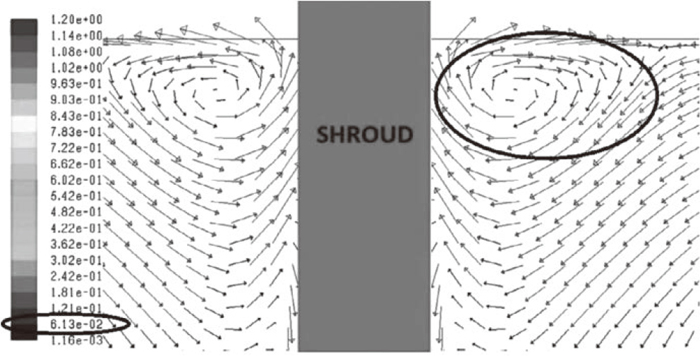
Predicted velocity fields from the numerical model under transient conditions at gas-flow/water-flow rate ratios of 6 pct.61)
However, for relatively fine bubbles (0.845 mm), it was reported that they tend to follow the melt flow, which thus reduce the tendency of forming the reverse flow.54)
In a newly published work by Mazumdar et al.,64) it was claimed that the ratio of argon could reach up to around 25% in fact by summarizing the casting parameters in several steelmaking plants. 10% to 50% gas volume was considered in the work of Wang et al.58) This means that volume of fluid (VOF) is more appropriate to predict the two-phase flow, which should be considered to model the two-phase flow in the ladle shroud.
4.3.2. MisalignmentEven when the ladle shroud is slightly misaligned, a biased jet flow is formed and hits the tundish pool. Consequently, the turbulence is unevenly distributed, and steel-argon plume becomes biased with the formation an eccentric TOE.65) What is worse is that the jet exposure can give rise to intense slag-steel emulsification and slag entrapment, especially during ladle change.65,66)
Possible remedial measures can be realized by using upgraded control devices and optimizing the operations. A three-plate sliding gate system was proposed,67) which permits the stationary plate and tube holder in axial alignment and hence avoids the lateral movement.65,68) A new hydraulic manipulator was developed in POSCO to solve the problem of misalignment.28) Compared with the conventional manipulator, each joint of the new manipulator included a torque sensor to detect the external forces imposed on the ladle shroud, and to measure the degree of misalignment. Furthermore, force integral controller was employed to adjust in real-time with the assistance of the joint torque sensing technique. A self-locking holding device has recently been proposed in RAMON Science & Technology Co., Ltd.,69) where no manipulator is required and the automatic positioning of the ladle shroud is enabled. A new TUNFLOW impact pot was developed by RHI Magnesita,27) which can minimize the unevenly distributed turbulence caused by misalignment. The key operational strategies are reducing the ladle-change duration and avoiding the occurrence of un-submerged ladle shroud.65)
4.3.3. Submergence DepthTo relief the turbulence in the pouring region, turbulence inhibitor, TLS and large-capacity have demonstrated encouraging results. Another method is to increase the submergence depth of the ladle shroud to dissipate the jet turbulence.70) However, the increased submergence depth also required a deeper tundish pool so as to reduce the refractory erosion of the tundish bottom. Chattopadhyay et al.70) concluded that the operation of high-depth submergence works like a turbulence inhibitor, which lowers the turbulence and the possibility of slag entrainment. Cwudziński et al.71) demonstrated that the increase the immersion depth from 0.1 m to 0.4 m contributed to around 10% increase for the transition zone during grade change in a CC process.
4.3.4. Opening and Closing of Slide GateThe flow rate through the ladle shroud is controlled by adjusting the opening and closing of the abovementioned slide gate. The crossing area between two eccentric circular faces forms the inlet area for the lower nozzle from the sliding side as shown in Fig. 12(a). Vortices are generated around the main stream as illustrated in Figs. 12(b) and 12(c) when the slide gate is half-open. Detailed flow structure between the lower nozzle and the ladle shroud was reported in Ref.54,72) Besides, the one-side opening generates biased flow and impacts at one side of the inner lining of the ladle shroud. It is noted from Figs. 12(d) to 12(f) that the biased inflow has not been completely dispersed and the outlet jet tends to flow out at a biased degree of θ, as indicated in Fig. 12(d). As a result, the velocity profile at the outlet is not concentric when the slide gate is partly open. It is shown in Figs. 12 (g) and 12(h) that the shift between the flow center and the geometric center (d1 and d2) was noticed in a CLS and a TLS. This biased flow could be related to the formation of eccentric TOE due to the emission of argon bubbles.48) Different opening, such as 1/4 and 3/4, will be considered at different casting speeds to discuss the effect of casting parameters on the flow pattern.
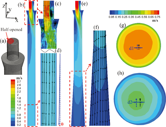
(a) The meshing of the ladle shroud with a half-opened inlet. (b) The time-averaged velocity contour of the whole CLS for 30 s. (c) An instantaneous flow profile at the inlet part of the CLS. (d) The mean velocity contour and trajectories at the outlet part of the CLS. (e) The time-averaged velocity contour of the whole TLS for 30 s. (f) The mean velocity contour and trajectories at the outlet part of the CLS. (g) Mean velocity contours at the outlet of (g) CLS and (h) TLS. (b-f) share the same legend at the left-bottom corner. (g) and (h) share the same legend at the right-top corner. (Online version in color.)
Removal and detection of slag carry-over at the end a casting heat is a vital task in the CC process. Visual examination was the primitive method to detect the slag, which is not reliable to offer a quick feedback. Also, the use of the ladle shroud disables the visibility to view the ladle stream. A variety of slag detection techniques have been developed to detect the slag carry-over from the ladle, such as electromagnetic methods, weight monitoring technique, optical methods and supersonic detection.2,22) Among them, electromagnetic detection is the most widely used technique thanks to its superior accuracy and response sensitivity. Nevertheless, some crucial issues are also challenging its application, including high manufacture and maintenance cost, complex installation and short service life.73) A promising alternative is monitoring the different vibration signals caused by the different densities between steel and slag. When there is slag entrainment, the vibration amplitude decreases. The mechanisms of the vibration detection are schematically shown in Fig. 13. This indirect detecting method has several advantages:22) 1) it can realize prior detection for the slag carry-over for the funnel vortex; 2) the indirect detection on the manipulator allows long service life; 3) simple mechanical structure and low cost. Toshino et al.74) brought up this strategy in Kawasaki Steel in 1980s, which was then implemented in BHP and NKK. It has been founding increasing applications in continuous casters.
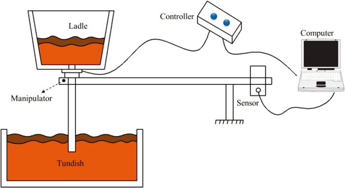
The main principle of the vibrational detection technique. (Online version in color.)
Yenus et al.75) have recently reviewed the application of the vibration technique in monitoring the metallurgical process, such as slag exposure and carry-over. These vibration signals can be captured from the shroud manipulator and provide feed-forward information to the controlling system of the slide gate, once the slag flows into the stream. The signal acquisition, data analysis and system architecture to realize the control algorithm was detailed in Ref.76) The issue of this technique is that the vibration signal is relatively weak and sometimes random, requiring high-level signal recognition algorithm and debugging process. This can be improved by research on the forming fundamental of the vibration signal and optimization of signal response & processing algorithm.77) A nonlinear vibration sensing model was built in the work of Tan et al.,78) which claimed that the detection accuracy can reach as high as 100%. The application of Nupro slag detection system on a slab caster at Imexsa demonstrated that the tundish slag thickness was decreased by around 80%.74) It can also work with optical detecting methods synergistically to increase the sensing reliability.
Compared with non-shrouded teeming, another benefit of using a shroud is the reduction of melt temperature loss from the ladle to the tundish, and the temperature difference was estimated to be 5 to 8°C.2) To maintain a pre-determined pouring temperature (preferentially low superheat) and prevent the temperature drop of molten steel, especially at the start/end of a casting heat and during ladle change, tundish heating techniques have been introduced, such as channel induction heating and plasma heating.79) The induction heater has been usually installed around the tundish pool, which makes the tundish set-up complex and difficult for maintenance. Xu et al.80) has recently proposed a concept of heating the ladle stream using an induction heater, namely heating the melt between the ladle and the tundish, as illustrated in Fig. 14. Compared with the channel heating, this method requires no structural change of the tundish and is easy to install and maintain, which makes it potential to be applied in any existing casting mill where tundish heating is needed. However, as this new heating device is exposed above the tundish pool, a combined system of fixing, cooling and protection should be developed to practice the induction heating at steelworks.
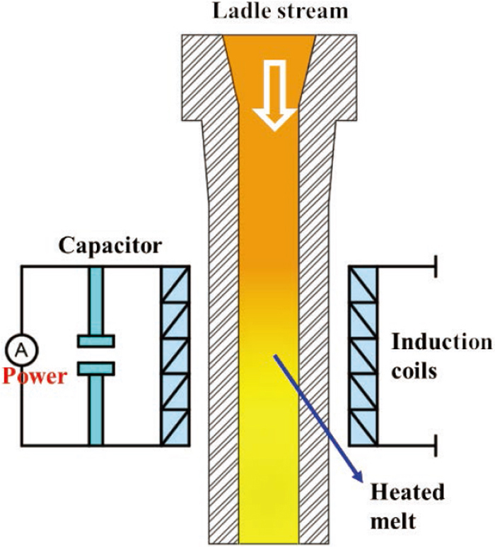
An illustration of the induction heating on the ladle stream. (Online version in color.)
The scope of tundish metallurgy also includes introducing additives into the liquid pool, such as alloy, rare earth element and fine oxide particulate, so as to adjust the composition and optimize the steel microstructure. Ladle shroud is a possible option to be mounted with a port for the injection of fine powders, considering the fact that the turbulence inside the ladle shroud is intense to disperse the injected powder and tundish is a good mixing pool. Kang et al.81) examined the efficiency of injecting Fe-25% B powders using argon as a carrier from the ladle shroud and the yield rate reached up to 90%.
There are still limited industrial trials on the technique of injecting additives from the ladle shroud. As the ladle shroud is installed and uninstalled during every ladle change, it seems more convenient to inject the additive from the fixed stopper which has been practiced already. However, the mixing of injected powder inside a tundish is usually much better than that inside a casting mold, especially for the casting of thin slabs and billets.
This article has concluded that remarkable progress has been made in the development and optimization of ladle shroud. Ladle shroud has been becoming a functional device in tundish metallurgy.
• The initial shrouding performance of the teeming stream has been significantly upgraded, which can meet the clean steel production in most cases. Attentions are mainly needed to be paid on optimizing the operational accuracy and efficiency of the shrouding assemblies, especially during transient periods.
• It is promising to design a new shrouding structure to enhance the flow pattern inside the ladle shroud and control the fluid flow inside the tundish pool. Various designs of ladle shrouds have been proposed, including two types of industrialized ones. Considering the multiple advantages of the TLS over the CLS in tundish metallurgy, the TLS is highly recommended in practices. However, the actual performance is also related to the specific tundish design (e.g. tundish volume) and flow control devices. The new ladle shroud designs showed positive effect on the fluid pattern on a laboratory scale; the feasibility of actual manufacturing and serving performance, nevertheless, has not been examined.
• Apart from the internal structural design of the ladle shrouds, the operational condition is critical to their performances. The misalignment of the ladle shroud is detrimental to both the shrouding performance and the flow pattern in the tundish. To ensure the alignment, sensing, holding technologies and new design of the ladle shroud system have shown promising performance. Flow control devices are suggested in the pouring zone to relieve the unexpected biased flow caused by the misalignment.
• It is essential to achieve a solid understanding of the fundamentals towards the multiphase flow inside both the ladle shroud and the tundish, which will in turn facilitate the data-driven precise modelling and control of the steel-argon-slag flow. The mechanisms of forming fine bubbles are still under exploration. High-order modelling methods, such as LES and Direct Numerical Simulation, are rarely employed.
• The detection of vibrational signals on the ladle shroud has been practiced to minimize the slag carry-over from the ladle.
• It could be an interesting topic to use the induction heating technique to heat up the teeming stream from the ladle shroud. It is a possible alternative to feed additives from the ladle shroud considering the favorable flow pattern. However, the development of these new techniques is still in their infancy yet.
The authors appreciate the valuable study of the referred literature. The authors are indebted to the funding of NSFC (No. 51822401) and China Postdoctoral Science Foundation. The authors are grateful of the suggestable discussion with Mr. Wenhan Ying from Zhejiang Tieshi Refractories.