Fundamentals of High Temperature Processes
Development of Low-fluoride Slag for Electroslag Remelting: Role of Li2O on the Crystallization and Evaporation of the Slag
2020 Volume 60 Issue 5 Pages 840-847

Details
2020 Volume 60 Issue 5 Pages 840-847
To reduce environmental pollution caused by fluoride from conventional electroslag remelting (ESR)-type slag and meet the requirements of vacuum ESR, it is strongly needed to develop low-fluoride and fluoride-free slag. The crystallization behaviors and evaporation of CaF2–CaO–Al2O3–MgO–Li2O slag as a candidate for low-fluoride ESR-type slag were studied. The sequence of crystal precipitation in CaF2–CaO–Al2O3–MgO–Li2O slag during cooling process was 11CaO·7Al2O3·CaF2 to CaO, followed by CaF2. The dominant crystalline phase in the slag was 11CaO·7Al2O3·CaF2. The liquidus temperature and crystallization temperature of slag decreased significantly with increasing Li2O content from 1.59 mass% to 4.46 mass%. Increasing Li2O contents suppressed the crystallization behaviors of ESR-type CaF2–CaO–Al2O3–MgO–Li2O slag. The weight loss of the slag melts increased with increasing Li2O content in the slag from 1.59 mass% to 4.46 mass%. The gaseous species evaporated from the slag melts were mainly LiF and contained a few amounts of CaF2. A proper amount of Li2O could be considered as an effective component for the design of low-fluoride ESR-type slag. Serious fluoride evaporation of LiF from CaF2–CaO–Al2O3–MgO–Li2O slag melts takes place when Li2O content exceeds a critical value.
Electroslag remelting (ESR)-type slag is CaF2–CaO–Al2O3-based system with minor additions of MgO, TiO2 and/or SiO2 to tailor the slag for specific remelting requirements.1) Conventional commercial ESR slag contains a large amount of CaF2 (typically 50–70 mass%), aiming to reduce the melting temperature and viscosity of the slag. Although CaF2 plays an important role in ESR slag, the evaporation of fluoride from conventional ESR slag melts during practical ESR process has always been an extremely serious issue.2,3,4) Low-fluoride slag and fluoride-free ESR slag not only can reduce environmental pollution, but also is needed for vacuum electroslag remelting which is considered a promising technology.
Even though it is well known that a series of problems arise when using high-fluoride ESR slag, the special steel plants around the world have been applying these slags for ESR production. Up to now, only a few studies have been reported regarding the development of fluoride-free or low-fluoride slag for ESR. Narita et al.5) verified that the surface quality of as-cast ingot was strongly improved through improving heterogeneous slag skin formation by adding 20% CaF2 addition in the (47.2–50.3 mass%)CaO-(45.0–48.9 mass%)Al2O3-(MgO) slag. Liang et al.6) reported that fluoride pollution and power consumption could reduce about 30% by using 49.5 mass%CaO-43.7 mass%Al2O3-6.8 mass%SiO2 in comparison with 60 mass%CaF2-20 mass%CaO-20 mass%A12O3 slag. Mao et al.7) demonstrated the applicability of proposed (42–50 mass%)CaO-(48–52 mass%)Al2O3-(MgO) slags in ensuring as-cast ingot quality, but the difficulties in liquid slag starting and the stability of ESR refining remained to be solved. The problems caused by the application of these fluoride-free slags in ESR production have been clarified by Li,8) including the difficulties in liquid slag starting, control of as-cast surface quality, non-metallic inclusions removal, desulfurization and electrical parameter, etc. These issues are closely dependent on the thermo-physical properties of the slag, i.e., melting temperature, viscosity, crystallization, and electrical conductivity.
To date, fluoride-free slag has not been applied in practical ESR production yet. Considerable efforts are strongly required to develop fluoride-free or low-fluoride slag for ESR. The crystallization properties of slag exert significant effects on the horizontal heat transfer and lubrication performance during drawing-ingot-type ESR. The inappropriate horizontal heat transfer through slag film and/or poor lubrication performance of slag generally results in unreliable operating practice and surface defects on as-cast ESR ingot.9,10) Therefore, in-depth knowledge on the melting and crystallization of low-fluoride ESR slag is necessary for the development of applicable low-fluoride slag. To develop fluorine-free mold flux, Wang et al.11) showed that Li2O addition could reduce the melting and crystallization temperature, as well as inhibit the formation of high melting temperature crystal in CaO-SiO2-4 mass%Al2O3-6 mass%B2O3 slag. Lu et al.12) proposed that the initial crystallization temperatures of CaO-Al2O3-based mold flux containing 11.26 mass%SiO2-Na2O-10.35 mass%F decreased with the increase in Li2O content from 2.48 mass% to 7.08 mass%. Zhou et al.13) reported that the crystallization of CaO-Al2O3-based mold fluxes is inhibited first and then enhanced when the Li2O content increases from 1 to 6 mass%. These previous studies provide a general guide to developing low-fluoride slag for ESR, suggesting that Li2O could be a potential substitute for CaF2 to meet the critical requirements for ESR-type slag.
In the authors’ previous study,14) the role of Li2O on the viscosity and structure on the low-fluoride slag has been studied. As a successive work in developing low-fluoride slag for ESR, the role of Li2O on the crystallization behaviors and evaporation of CaF2–CaO–Al2O3–MgO–Li2O slag were studied by differential scanning calorimetry (DSC) in the present work. The crystalline phases and their microstructure were identified by combing scanning electron microscope (SEM) equipped with energy dispersive X-ray spectroscopy (EDS) and X-ray diffraction (XRD).
Reagent-grade powders of CaCO3 (≥99.0%), CaF2 (≥99%), Al2O3 (≥99.99%), MgO (≥98.5%), and Li2CO3 (≥98.0%) were used to produce slag samples. CaO was obtained from reagent-grade CaCO3 powders which were calcined at 1323 K (1050°C) for 12 hours. Li2CO3 powders were taken as raw materials of substitutes for Li2O. The thoroughly mixed powders were melted at 1773 K (1500°C) in a platinum crucible to ensure complete melt and homogenization, and subsequently the liquid sample was quenched in iced water. The quenched slag was then ground. X-ray fluorescence (XRF) spectroscopy (Rigaku ZSX Primus II, Japan) was employed to determine the chemical compositions of pre-melted slag. Li concentration of the slag was measured using inductively coupled plasma-optical emission spectroscopy (ICP-OES). The chemical composition of the pre-melted slag is listed in Table 1.
| Sample No. | CaF2 | CaO | Al2O3 | MgO | Li2O |
|---|---|---|---|---|---|
| L1 | 20.99 | 40.45 | 33.98 | 2.99 | 1.59 |
| L2 | 20.43 | 40.21 | 32.77 | 3.08 | 3.51 |
| L3 | 19.62 | 40.19 | 32.69 | 3.02 | 4.46 |
The crystallization characteristics of the slag were studied using DSC (Netzsch STA 449F3; Netzsch Instrument Inc., Germany) in Ar gas atmosphere. For each DSC measurement, approximately 45 mg of sample powders was heated at a constant heating rate of 25 K/min from room temperature up to 1733 K (1460°C) in a platinum crucible with a diameter of 5 mm and a height of 5.5 mm, and held at this temperature for 3 minutes to eliminate bubbles and homogenize its chemical composition. Subsequently, the liquid sample was cooled at a constant cooling rate (10 K/min, 15 K/min, 20 K/min, and 25 K/min, respectively) to the temperature below 473 K (200°C). The DSC signal was recorded automatically during both heating and cooling cycles.
2.3. SEM-EDS and XRD AnalysisThe crystalline phases and crystal compositions of solidified slag after DSC measurements were determined by SEM (FEI Quanta-250; FEI Corporation, Hillsboro, OR) equipped with EDS (XFlash 5030; Bruker, Germany). Before SEM-EDS determination, the solidified slag samples were mounted with epoxy resin and polished, and then thin platinum film was coated onto the cross section of the polished sample.
To identify the crystalline phase corresponding to exothermic peak on DSC curves, a series of continuous cooling followed by quenching experiments were carried out to prepare slag sample for XRD analysis. The thoroughly mixed slag was melted in a platinum crucible at 1733 K (1460°C) for 3 minutes, followed by a continuous cooling of liquid slag at a cooling rate of 10 K/min to 1073 K (800°C). Once reaching 1073 K (800°C), the slag sample was quenched and the crystalline phases in the quenched samples were analyzed by XRD with Cu-Ka radiation.
Figure 1 shows the DSC curves of slag melts at four different cooling rates, i.e., 10 K/min, 15 K/min, 20 K/min, and 25 K/min, respectively. It was observed that there were three separate exothermic peaks on the DSC curves at each cooling rate, suggesting discrete crystallization of three phases. It was observed that the intensity of the second crystallization exothermic peak in Fig. 1(a) and the second and third crystallization exothermic peak in Fig. 1(c) were much smaller than those of other exothermic peaks on the same DSC curves, which suggested that the corresponding crystallization was extremely weak.

DSC curves of non-isothermal crystallization of slag melts at various cooling rates. (Online version in color.)
Figure 2 shows the XRD patterns of the slag quenched at the temperature below the crystallization end temperature on the DSC curve at the cooling rate of 10 K/min. The results confirm that three crystalline phases in each slag are identified by XRD, i.e., 11CaO·7Al2O3·CaF2, CaO, and CaF2, which are consistent with the DSC results. FactSage 6.4 (CON2 database) calculation result shown in Fig. 3 reveals that the sequence of crystal precipitation in CaF2–CaO–Al2O3–MgO–Li2O slag during cooling process is 11CaO·7Al2O3·CaF2 to CaO, followed by CaF2. It should be noted from Fig. 3 that MgO theoretically precipitates after 11CaO·7Al2O3·CaF2 from the slag melts. Considering that the MgO content in the original slag is low and no MgO crystals was identified by XRD analysis, the MgO precipitation in the studied slag is ignored.

XRD patterns of the slag melts quenched at 800°C (1073 K).
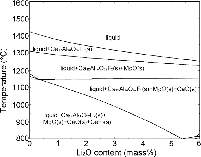
Phase diagram of 20%CaF2-40%CaO-33%Al2O3-3%MgO-xLi2O (x: variable) calculated by FactSage 6.4 (CON2 database).
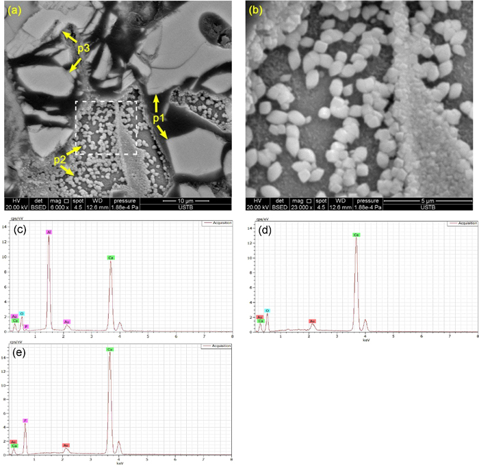
The crystals and their compositions in the solidified slag after DSC measurements were determined by SEM-EDS. Combining SEM-EDS with XRD results, the crystalline phases could be identified. Figures 4 and 6 show the SEM images and EDS spectrums of solidified slags. It can be confirmed from SEM-EDS results that three crystalline phases were found in the studied slag samples, which was consistent with the DSC and XRD results. According to EDS spectrums and XRD patterns, the three crystalline phases observed in the SEM micrographs of the solidified slags are determined to be 11CaO·7Al2O3·CaF2, CaO and CaF2, respectively. The crystalline phases are designated in the order of precipitation as p1, p2, and p3, respectively. The dominant crystalline phase in the solidified slag was 11CaO·7Al2O3·CaF2. The morphology of 11CaO·7Al2O3·CaF2 changed from faceted (shown in Fig. 4(a)) to blocky (shown in Figs. 5(a) and 6(a)) with increasing Li2O content from 1.59 mass% to 4.46 mass%. Moreover, the size of 11CaO·7Al2O3·CaF2 became smaller. Many granular CaO and spherical CaF2 were observed in each solidified slag. There is no change in the morphology and size of CaO and CaF2 in the slag with different Li2O contents.

BSE images of slag L1 after DSC measurement at the cooling rate of 15 K/min. Note: Fig. (b) is enlarged image of the enclosed area in Fig. (a). EDS spectrums shown in Figs. (c), (d) and (e) correspond to the phases p1, p2, and p3 shown in Fig. (a), respectively. (Online version in color.)
BSE images of slag L2 after DSC measurement at the cooling rate of 15 K/min. Note: Fig. (b) is enlarged image of the enclosed area in Fig. (a). EDS spectrums shown in Figs. (c), (d) and (e) correspond to the phases p1, p2, and p3 shown in Fig. (a), respectively. (Online version in color.)

BSE images of slag L3 after DSC measurement at the cooling rate of 15 K/min. Note: Fig. (b) is enlarged image of the enclosed area in Fig. (a). EDS spectrums shown in Figs. (c), (d) and (e) correspond to the phases p1, p2, and p3 shown in Fig. (a), respectively. (Online version in color.)
The crystallization temperature of slag melt corresponds to the temperature at which crystallization just begins in non-isothermal crystallization process. To reveal the crystallization behavior of the slag with different Li2O contents, the CCT diagrams of slag melts were constructed based on the determined crystallization temperature combined with the time-temperature profiles recorded in DSC measurement, as shown in Fig. 7. The crystallization temperatures of the crystalline phases in each slag sample were observed to decrease with the increase in continuous cooling rates in DSC measurements. The present result is in accordance with the finding reported by the present authors. The detailed discussion in regard of this trend has been presented in previous study.14)

CCT diagrams of slag samples with different Li2O contents. (Online version in color.)
Figure 8 shows the CCT diagrams of the first crystalline phase precipitated from the slag melts. As pointed out in previous studies, the crystallization temperature of the first crystalline phase correspondingly is the crystallization temperature of the slag melt.9,10) The crystallization temperature of the slag melt was observed to decrease significantly with increasing Li2O content in the slag. The similar findings were also reported by others.11,12) Pervious study14) confirmed that Li2O could act as network breaker in mold flux to break the network structures of slag melts. Under this condition, the element diffusion from liquid to interface was accelerated, which was conducive to crystallization. However, the overall crystallization tendency of the studied slag decreased with the addition of Li2O. That was because that the tendency of Li2O reacting with Al2O3 in the slag melts to form LiAlO2 lowered the activity of Al2O3.12) The FactSage 6.4 (CON2 database) calculation results show that the activity of Al2O3 in the slag melts at 1773 K (1500°C) is 0.028, 0.018 and 0.012, respectively. It suggested that the activity of Al2O3 decreased obviously with the increase in Li2O content in the slag, resulting in the decreasing of available content of Al2O3 as a main component of the first crystalline phase 11CaO·7Al2O3·CaF2. Therefore, the crystallization tendency of the slag decreased with the addition of Li2O in the slag.

CCT diagram for the first crystalline phases precipitated in the slag. (Online version in color.)
The melting characteristics were evaluated by determining the liquidus temperature Tliq of the slag with varying Li2O content. The liquidus temperature Tliq is the temperature obtained by extrapolating the crystallization temperatures of slag at cooling rates of 10, 15, 20 and 25 K/min determined by DSC to the value corresponding to the cooling rate of 0 K/min. The liquidus temperature Tliq of CaF2–CaO–Al2O3–MgO–Li2O slag is 1704 K (1431°C), 1687 K (1414°C) and 1663 K (1390°C), respectively. It was observed to decrease significantly with increasing Li2O content in the slag from 1.59 mass% to 4.46 mass%.
The undercooling of slag melt crystallization was calculated by subtracting the crystallization temperature of the slag at various cooling rates from its liquidus temperature, as shown in Fig. 9. It was clear that the undercooling of slag melt crystallization increased with increasing Li2O addition in the slag, which was an indication of decreased crystallization ability of low-fluoride ESR slag with Li2O addition.

Undercooling of slag melts crystallization at various cooling rates. (Online version in color.)
Figure 10 presents the thermogravimetry (TG) curves of the slag at various cooling rates. It can be seen that the main weight loss is approximately located at the stage from 1373 K (1100°C) during heating process to 1523 K (1250°C) during cooling process. There was liquid phase in the slag in this process. The values of maximum weight loss of the slag with Li2O content from 1.59 mass% to 4.46 mass% were 3.6 mass%, 4.5 mass% and 8.5 mass%, respectively. The weight loss of the slag evidently increased with the increase in Li2O content in the slag.

TG curves of the slag at various cooling rates. (Online version in color.)
The weight loss of the slag melts at elevated temperature results from the evaporation of the fluoride. The gaseous species that evaporated from the slag melts at various temperatures were calculated using FactSage 6.4 (CON2 database), as shown in Fig. 11. The gaseous species evaporated from the slag melts were mainly LiF and contained a few amounts of CaF2. The weight of LiF evaporated from the slag melts increased obviously with increasing Li2O content in the slag. Fluoride evaporation from slag melts is dependent on the temperature and chemical composition in terms of component activities and viscosity.16,17) The FactSage 6.4 (CON2 database) calculation results show that the activity of Li2O in the slag melts at 1773 K (1500°C) is 0.00017, 0.00082 and 0.00213, respectively. The activity of Li2O in the slag melts obviously increases with the addition of Li2O from 1.59 mass% to 4.46 mass%, which is in favor of the LiF evaporation. Moreover, the previous study14) confirmed that the viscosity of the present slag decreased obviously with increasing Li2O content in the slag. The lower viscosity of slag reduced the resistance of the diffusion of slag components, which was conducive to fluoride evaporation.

Weight of evaporation species at different temperature from the slag melts with various Li2O contents. (Online version in color.)
Combined the previous studies and the results in the present study, it can be concluded that the Li2O addition can decrease the crystallization temperature and viscosity of the low-fluoride ESR-type CaF2–CaO–Al2O3–MgO–Li2O slag, which is conducive to desulfurization, inclusions removal and providing a sound condition for the good surface quality of the as-cast ingot. Nevertheless, the evaporation of fluoride from slag melts becomes more serious with adding excessive Li2O in the slag. The role of Li2O on the thermo-physical property of mold flux have been elaborated by many researches.11,12,13,18,19,20) They confirmed that small amount of Li2O addition can decrease the crystallization temperature11,12) and viscosity of mold flux.19,20) The role of Li2O on the thermo-physical property of low-fluoride ESR-type slag is similar to that of mold flux. Moreover, Li2O and CaF2 has the same influence on the crystallization behaviors and viscosity of ESR-type slag. Therefore, a proper amount of Li2O could be considered as an effective component for the design of low-fluoride ESR-type slag. However, serious fluoride volatilization of LiF from CaF2–CaO–Al2O3–MgO–Li2O slag takes place when Li2O content exceeds a critical value.
The role of Li2O on the crystallization behaviors and evaporation of CaF2–CaO–Al2O3–MgO–Li2O slag were studied by DSC combined with SEM-EDS and XRD in the present work. The conclusions are summarized as follows:
(1) The sequence of crystal precipitation in CaF2–CaO–Al2O3–MgO–Li2O slag during cooling process was 11CaO·7Al2O3·CaF2 to CaO, followed by CaF2. The dominant crystalline phase in the slag was 11CaO·7Al2O3·CaF2. With addition of Li2O in the slag, the morphology of 11CaO·7Al2O3·CaF2 changed from faceted to blocky. The morphology of CaO and CaF2 were granular and blocky, respectively, irrespective of Li2O contents in the slag.
(2) The liquidus temperature and crystallization temperature of slag decreased significantly with increasing Li2O content from 1.59 mass% to 4.46 mass%. Increasing Li2O contents suppressing the crystallization behavior of the slag was due to that Li2O lowering the activity of Al2O3 in the slag melts reduced the available content of Al2O3 as a main component of the first crystalline phase 11CaO·7Al2O3·CaF2 and retarded 11CaO·7Al2O3·CaF2 formation.
(3) The weight loss of slag melt increased with increasing Li2O content from 1.59 mass% to 4.46 mass%. The gaseous species evaporated from the slag melts were mainly LiF and contained a few amounts of CaF2.
(4) A proper amount of Li2O could be considered as an effective component for the design of low-fluoride ESR-type slag. Serious fluoride volatilization of LiF from CaF2–CaO–Al2O3–MgO–Li2O slag takes place when Li2O content exceeds a critical value.
The financial support by the National Natural Science Foundation of China (Grant No. 51874030, 51874026 and 51774225), the Fundamental Research Funds for the Central Universities (Grant No. FRF-TP-18-004A3), and Guangdong YangFan Innovative & Entepreneurial Research Team Program (Grant No. 2016YT03C071).