Abstract
Our strategy is to enhance the fracture property of ultra-high-strength low-alloy steels with a yield strength of 1.4 GPa or over by arresting the propagation of brittle cracks in hierarchical, anisotropic, and ultrafine-grained structures. This provides a fail-safe design in addition to suppressing crack initiation. The present article reviews the strength, ductility, toughness, and delayed fracture resistance of ultra-high-strength low-alloy steels with ultrafine elongated grain structures processed by the deformation of tempered martensitic structures at elevated temperatures (referred to as warm tempforming). The evolution of heterogeneous microstructures during warm tempforming using multi-pass caliber rolling is discussed, as are the microstructural factors controlling the strength and fracture properties of warm tempformed steels. Furthermore, we apply warm tempformed steels with ultrafine elongated grain structures to the fabrication of ultra-high-strength bolts.
1. Introduction
Tempered lath martensite is one of the important microstructures in high-strength steels. Nano-sized carbides are dispersed in its hierarchical and heterogeneous structure, in which prior-austenite grains are divided into several packets that are further subdivided into blocks containing groups of laths with similar crystallographic orientations. In lath martensite, a block can be recognized as an effective grain,1) and the block size is as small as a few μm or less in medium-carbon low-alloy steels.2,3) By considering such a fine heterogeneous structure, we have developed a thermomechanical treatment in which a tempered martensitic structure is deformed at an elevated temperature (referred to as warm tempforming)4,5,6,7,8,9,10,11,12,13,14,15,16,17,18,19,20,21,22,23,24) to create an ultrafine-grained structure. The influence of warm tempforming on the evolution of ultrafine-grained structures and mechanical property is systematically investigated in medium-carbon low-alloy steels.
Figure 1 plots the Charpy V-notch impact absorbed energy, vE, as a function of yield strength, σys, at room temperature for various steels.23,24) High-alloy steels,25,26,27,28,29) which are typified by maraging steels, have been developed through 1) reducing the amounts of inclusions and impurity elements such as P and S, 2) minimizing the amount of C, 3) adding alloying elements such as Ni, and 4) refining the prior-austenite grain size. These steels exhibit a much better balance of σys and vE than low-alloy steels.30,31,32,33,34,35) However, even in high-alloy steels, the vE decreases to 40 J or less at an ultra-high σys of ≥ 1.8 GPa.29) As for low-alloy steels, the addition of C is usually necessary to attain ultra-high strength. This fact indicates that a breakthrough in the balance between σys and vE is very difficult to achieve through the conventional microstructure control of ultra-high-strength low-alloy steels. On the other hand, we have successfully enhanced the vE of medium-carbon low-alloy steels through the warm tempforming process using multi-pass caliber rolling.5) In a 0.4%C-2%Si-1%Cr-1%Mo steel (mass%), the vE of a warm tempformed (TF) steel (◆) increased to 200 J or more at a σys of 1.8 GPa. Furthermore, we found that the TF steel exhibited an inverse temperature dependence of toughness. The vE was enhanced from room temperature to subzero temperatures, at which the quenched and tempered (QT) steel (◇) failed in a brittle fracture mode, as described later. Similar inverse temperature dependence of toughness has already been observed in an ausformed 0.2%C-3%Ni-3%Mo steel (▲)34); however, it occurred at around 200°C, and vE decreased to approximately 30 J at room temperature.

The remarkable enhancement of the Charpy impact property by warm tempforming is due to the evolution of an anisotropic microstructure consisting of ultrafine elongated grains (UFEGs) with a strong <110>//rolling direction (RD) fiber texture. This anisotropic structure induces crack-arrester-type delamination, in which cracks branch in the longitudinal direction (//RD) of a notched bar specimen during impact loading.4,5,6,7,8,9,10,11,12) In crack-arrester-type delamination, the notch and/or crack tip become blunt, and a highly-triaxial tension state in the vicinity of the notch and/or crack tip is relaxed into a uniaxial one. The formation of microcracks along the RD may also lead to a stress fielding effect, thereby reducing the fracture driving force. Eventually, crack propagation in the striking direction (SD) of the notched bar specimen is suppressed by the crack-arrester-type delamination and vE is enhanced. Therefore, when cracks initiate and propagate in directions normal to the loading direction, this may lead to the suppression of fractures in materials. From this viewpoint, TF steel is considered to have a fail-safe function due to its UFEG structure.13) A fail-safe function is based on the concept that the system is arranged to mitigate damage and is controlled to the safety side when members and structures are damaged. In conventional ultra-high-strength steel, once brittle cracks initiate, they can quickly propagate in the loading direction owing to the isotropic grain structure. Hence, the main focus in the toughening of ultra-high-strength steels has been to suppress the initiation of brittle cracks. In contrast, the present study attempts to use the occurrence of brittle cracks to improve the fracture property of ultra-high-strength steel by controlling brittle crack propagation in an UFEG structure with an anisotropic property.4,5,6,7,8,9,10,11,12,13,14,15,16,17,18,19,20,21,22,23,24)
This paper presents a review of studies on the warm tempforming of medium-carbon low-alloy steels. Data are presented mainly for the 0.4%C-2%Si-1%Cr-1%Mo steel that was developed as a prototype ultra-high-strength steel. Research on the deformation of tempered martensitic structures is briefly reviewed in Section 2. Sections 3–5 review the relationships between ultrafine heterogeneous structures and tensile and Charpy impact properties in ultra-high-strength steels processed by warm tempforming using multi-pass caliber rolling.5,6,7,8,9,10,11,12) The criterion of microcrack initiation, and crack propagation behavior in a TF steel with an UFEG structure, are discussed in Section 6 based on evaluations of crack initiation and propagation under quasi-static loading.13,14,15,16,17,18) The delayed fracture property of TF steels19,20,21) and their application to ultra-high-strength bolts36) are introduced in Sections 7 and 8, respectively.
2. Deformation of Tempered Martensitic Structure
According to where the plastic deformation of steel is carried out following austenitizing treatment, Tamura classified thermomechanical treatments into three types: 1) deformation before phase transformation (e.g., ausforming), 2) deformation during phase transformation, and 3) deformation after phase transformation (e.g., patenting and cold drawing of piano wire).37) According to this classification, the deformation of tempered martensitic structures is a deformation after phase transformation, and there are names such as strain tempering, tempforming and so on.
Nishioka first observed a marked increase in tensile strength through the cold drawing of tempered martensitic structures in low-carbon low-alloy steels.38) Sekiguchi et al. proposed a thermomechanical treatment called warm-temper-forging in which a quenched steel is heated and directly forged into parts during the tempering process.39) When warm-temper-forging was applied to a JIS-S45C steel (0.45% C plain carbon steel) in a temperature range of 400–600°C, the resulting steel exhibited much higher ductility than conventional quenched and tempered steels in the tensile strength range of 1.0–1.3 GPa. Additionally, in comparison to conventional cold forging, the warm-temper-forging process was demonstrated to have two advantages: the working force during forging was reduced and the critical upsetting ratio was improved. Ohmori and Yamazaki40) attempted warm forming of modified-ausformed steel in the tempering process and investigated the combined effect of modified ausforming and warm tempforming on the mechanical property of JIS-SNC631 and SCM435 steels. They reported that when the modified-ausformed steel was plate-rolled at a temperature of 600°C with a rolling reduction of 50%, its strength increased but its ductility decreased in a σys range of 0.8–1.1 GPa.
Tokizane et al. investigated the cold and warm deformation of tempered martensitic structures in medium-carbon low-alloy steels in order to obtain prior-microstructures for austenite grain refinement through reversion treatment.41) They reported that the austenite grain size was refined to around 1 μm when the tempered martensitic structure was subjected to cold plate rolling with a rolling reduction of 80% followed by rapid austenitizing.
In recent years, the fine heterogeneous structure of martensite has attracted attention as a prior microstructure to create ultrafine, equiaxed, ferrite grain structures. Ultra-grain refinements to 1 μm or less have been reported using thermomechanical treatments such as cold plate rolling of a martensitic structure followed by annealing,42) warm multi-axial pressing of a tempered martensitic structure,43) and warm multi-pass caliber rolling of a tempered martensitic structure followed by annealing.44)
The purposes of our project are to 1) manufacture ultra-high-strength TF steel with an ultrafine elongated grain structure, and 2) fabricate members and parts (such as bolts) through the warm plastic deformation of tempered martensitic structures in medium-carbon low-alloy steel. We call this thermomechanical treatment “warm tempforming”.5) High-strength parts such as bolts are generally manufactured in a process where steels are softened through spheroidized annealing, cold-formed, then quenched and tempered. However, there is a trade-off between the strengthening and softening of steels, and cold formability is usually poor in ultra-high-strength low-alloy steels, which restricts their practical applications. In this regard, warm tempforming has the advantage of not requiring soft annealing during the manufacturing process.36)
3. Microstructure
3.1. Microstructural Evolution during Warm Tempforming
Figure 2 shows the microstructure of a 0.4%C-2%Si-1%Cr-1%Mo steel that was warm tempformed by multi-pass caliber rolling with different equivalent strains, εeq, at a temperature of 500°C.8) The changes in the microstructural factors as a function of εeq during warm tempforming are summarized in Fig. 3. The average prior-austenite grain size was 47 μm for the quenched and tempered (QT) steel before warm tempforming, and εeq was calculated from the relationship between rolling reduction (r) and εeq: εeq = 2/√3ln{1/(1 − r/100)}.45) Depending on the changes in the dislocation substructure and matrix grain structure, the microstructural evolution during warm tempforming to a εeq value of 1.75 (r = 78%) can be divided into three stages as a function of εeq. In the initial stage of warm tempforming (εeq ≤ 0.4), there are no significant changes in the morphologies of the blocks, packets, and prior-austenite grains (Fig. 2(a)), while sub-boundaries are formed through a process of dislocation annihilation and rearrangement, and the density of geometrically necessary (GN) dislocations46) increases.8) As indicated in Fig. 3, the KAM (kernel average misorientation) value,47) which is proportional to the GN dislocation density, shows an increase in an εeq range of 0–0.4, above which it levels off. In the middle stage of warm tempforming (0.4 < εeq ≤ 0.9), heterogeneous deformation becomes more pronounced at the μm-scale, and blocks, packets, and prior-austenite grains are extended in the RD (Fig. 2(b)). In the final stage, warm tempforming to an εeq value of 1.75 results in the evolution of an ultrafine elongated grain (UFEG) structure with a strong <110>//RD fiber texture (Fig. 2(c)). The high-angle boundary (HAB: boundary with a misorientation angle of 15° or over) area per unit volume was observed to markedly increase during the final stage of warm tempforming; ribbon-like grains might be formed through the extension of blocks in the RD, while the ratio of ultrafine rod-like and equiaxed grains increased. This suggests that a grain subdivision mechanism48) might contribute to grain refinement during the final stage of warm tempforming. Similar microstructural evolution has been observed in the cold drawing of pure iron wire.49) On the other hand, the ratio of the integrated intensity of the (110) XRD peak, Im, on the RD plane (⊥RD) to the integrated intensity of the (110) XRD peak, Is, for the standard samples, Im/Is, indicates the degree of development for the <110>//RD fiber texture. The value of Im/Is linearly increases with εeq and, at εeq = 1.75, it is approximately seven times higher than that of the QT steel before warm tempforming (Fig. 3). The development of a strong <110>//RD fiber texture is commonly observed in the cold drawing of pure iron,49) ferrite-martensite dual-phase steel (Scifer),50) and ultra-high-carbon steel.51) Bourell reported that the degree of development of a {100}<110> deformation texture was independent of rolling temperature but increased with increases in rolling reduction when low-carbon ferritic steels were warm plate-rolled at temperatures of 540–650°C.52)

Furthermore, carbide particles tend to grow slightly and become spheroidized during warm tempforming (Fig. 3), and the long axes of intergranular carbide particles are mostly aligned parallel to the RD (Fig. 2(f)). During warm tempforming, these nano-sized carbide particles might promote the accumulation of GN dislocations and retard grain growth through their pinning effect and, thus, they play an important role in the evolution of ultrafine-grain structures.
3.2. Hierarchical Heterogeneity in TF Steel with an UFEG Structure, and its Control
As explained above, the hierarchical heterogeneity of warm tempformed steel evolves through the extension of blocks, packets, and prior-austenite grains in the RD in tempered martensitic structures with dispersed nano-sized carbide particles. The heterogeneous deformation of blocks and packets is greatly influenced by variations in their crystallographic orientation and geometric arrangement. The morphology and crystallographic orientation of block structures, which especially influence the evolution of ultrafine elongated grain (UFEG) structures, are different at each packet. Hence, as indicated by the arrows in Fig. 4(a), the warm tempformed (TF) steel with a εeq of 1.75 exhibits a hierarchical and heterogeneous structure consisting of band-like structures that are further subdivided by UFEG structures; the UFEG structures thus vary in morphology and crystallographic orientation according to the band-like structures.11) Since the band-like structures are considered to be inherited by packet structures, they are referred to as packet bands.11) The width of the packet bands is an important microstructural factor that controls brittle crack propagation in TF steel with an UFEG structure, as described later. Furthermore, the pole figures in Figs. 4(b), 4(c) demonstrate that there are many {100} cleavage planes for bcc iron distributed on the planes parallel to, and at ±45° to, the RD due to the strong <110> //RD fiber texture.

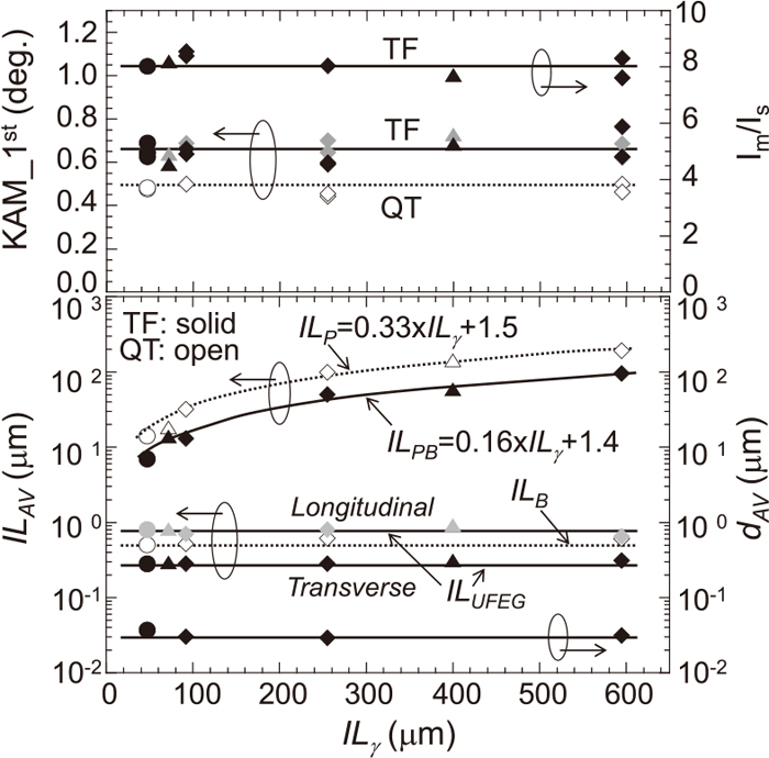
Figure 5 summarizes the microstructural factors of the hierarchical and heterogeneous structure of the TF steels with εeq = 1.75 as a function of the average intercept length of prior-austenite grains, ILγ, in the tempered martensitic structure before warm tempforming.11) The average intercept length of packets, ILP, varies depending on ILγ and is approximately one-third as long as ILγ. By contrast, the average intercept length of blocks, ILB, is measured to be 0.5–0.6 μm irrespective of ILγ. Block boundaries are defined as boundaries with a misorientation angle of 10° or more. Accordingly, the size of packet bands varies with ILγ, while the average intercept lengths in the UFEG structure, ILUFEG, are, respectively, 0.3 μm in the transverse direction (⊥RD) and 0.7 μm in the longitudinal direction (//RD), without dependence on ILγ. The average width of packet bands, ILPB, is approximately half the length of ILP, which supports the fact that the packets might be elongated in the RD at εeq = 1.75. Furthermore, the KAM value (∝GN dislocation density), average long-axis length of carbide particles, dAV, and Im/Is on the RD plane are almost constant, regardless of ILγ.
The TF steel was also characterized by having a bimodal carbide particle size distribution in its UFEG structure. For example, the dAV of the transgranular and intergranular carbide particles were measured to be 24 nm and 46 nm, respectively (Fig. 2(f)). Such a bimodal distribution of carbides might be inherited from that of the tempered martensitic structure. In the 0.4%C-2%Si-1%Cr-1%Mo steel that was quenched and tempered at a temperature of 500°C, most of dispersed carbides were confirmed to be cementite particles in which Cr, Mn and Mo were dissolved. Additionally, hydrogen absorption testing suggested the precipitation of Mo carbides during tempering.21)
The hierarchical heterogeneity of tempered lath martensite, as well as the warm tempforming conditions such as the deformation method, temperature, εeq, and so on, have great influences on the microstructural evolution during warm tempforming. Therefore, the microstructure control of tempered lath martensite is a key aspect in controlling the hierarchical heterogeneity of TF steel.
To refine the packet bands in TF steel, prior-austenite grain refinement53,54,55) and ausforming, in which the austenitic structure is deformed before martensitic transformation,34,40,56) were considered as pretreatments, because these techniques can effectively refine the packet size in the martensitic structure. For example, when a 0.4%C-2%Cr-1%Mo-2%Ni steel with ILγ = 25 μm was modified-ausformed with εeq = 1.5 and then tempformed by multi-pass caliber rolling at a temperature of 500°C, the average packet band width, ILPB, was refined to approximately 4 μm, even at a relatively small εeq of 0.7.12) This ILPB of 4 μm was almost the same as that in the TF steel that was multi-pass caliber rolled with εeq = 1.5; however, it should be noted that the degree of development of the <110>//RD fiber texture was larger when εeq = 1.5 than when εeq = 0.7, since it only depended on the value of εeq during warm tempforming.
Compared to a packet structure, the marked refinement of a block structure is not expected in medium-carbon low-alloy steel, since its block structure is originally fine. For example, in (0.2-0.6)%C-2%Si-1%Cr-1%Mo steels, the average intercept length of the blocks, ILB, decreased from 1 μm to 0.5–0.4 μm with increases in C content from 0.2% to 0.4–0.6%, and the average transverse intercept length, ILUFEG, in the UFEG structure decreased from 0.4 to 0.3 μm after warm tempforming using multi-pass caliber rolling at a temperature of 500°C with εeq = 1.75.9,10)
Additionally, a significant advantage of the presented warm tempforming technique is that precipitated carbide particles can be spheroidized at the nm-scale. In order to increase the grain boundary pinning effect and precipitation-strengthening ability with a small volume fraction of carbide particles,9,10) the carbide particles should be kept small during the warm tempforming process through the combined addition of small amounts of alloying elements57) and so on.
4. Tensile Property
4.1. Change in Tensile Deformation Behavior with Warm Tempforming
Figure 6 displays the nominal stress-strain curves of the warm tempformed 0.4%C-2%Si-1%Cr-1%Mo steels, whose microstructural features are shown in Figs. 2 and 3.8) Note that the tensile direction is parallel to the RD. The average values of yield strength, σys//RD, and tensile strength, σB//RD, for the quenched and tempered (QT) steel are 1.44 and 1.73 GPa, respectively. The tempered martensitic steel is strengthened and the average values of σys//RD and σB//RD increase to 1.84 and 1.83 GPa, respectively, after warm tempforming with εeq = 1.75. Warm tempforming has an especially strong influence on σys//RD. The TF steel (εeq = 1.75) exhibits discontinuous yielding behavior (characterized by a distinct yield point phenomenon) due to its UFEG structure, in contrast to the QT steel which exhibits a continuous yielding behavior. Similar yield point phenomena have been observed in cold-drawn iron wire49) and ultrafine-grained materials;44,58,59,60,61,62) however, it is often accompanied by a loss of uniform elongation (plastic instability occurs immediately after yielding). By contrast, the TF steel with an UFEG structure (εeq = 1.75) exhibits adequate uniform elongation equal to or greater than that of the QT steel. This is a common feature in warm tempformed medium-carbon low-alloy steel.4,5,6,7,8,9,10,11,12) Furthermore, the tensile ductility (indicated by reduction in area, RA) of the steel is usually improved by warm tempforming.

Figure 7 shows the tensile property of the TF steels with UFEG structures (εeq = 1.75), as a function of the average intercept length of prior-austenite grains, ILγ, in the tempered martensitic structure before warm tempforming, and testing temperature.11) Since the yield-to-tensile strength ratio of the TF steels is 1, the σB//RD data are omitted. The prior-austenite grain size has little influence on the σys//RD values of the TF steels. The σys//RD of the TF steels increases linearly as the testing temperature decreases from room temperature to −150°C, below which it tends to increase sharply. Such temperature dependence of σys//RD is the same regardless of the tensile direction, despite the anisotropic tensile property of the TF steels. Similarly, this was observed in the QT steels with an isotropic tensile property.9,10) The increment in σys between room temperature and −196°C was approximately 0.4–0.5 GPa regardless of the matrix grain structure in these bcc steels. The true fracture stress, σf, is the force at fracture divided by the minimum cross-sectional area at fracture, and the average value of σf//RD increases from room temperature to −150°C. However, the temperature dependence of σf//RD differs according to the prior-austenite grain size. At the same testing temperature, σf//RD becomes greater as the prior-austenite grain size decreases. At −196°C, the average value of σf//RD increases to 3.4 GPa for the TF steel with ILγ = 47 μm, while it decreases to 2.5 GPa for the TF steel with ILγ = 595 μm. Furthermore, the uniform elongation, Eu//RD, is hardly influenced by the prior-austenite grain size and testing temperature, while the reduction in area, RA//RD, decreases with decreasing testing temperature, particularly below −150°C. The deterioration degree of RA//RD becomes greater with increases in the prior-austenite grain size. At −196°C, the average RA//RD value of the TF steel with ILγ = 595 μm decreases to 10%. However, it should be noted that the TF steel with ILγ = 47 μm maintains a high RA//RD average value of 39% even though its σys//RD increases to 2.3 GPa at −196°C. Therefore, the σf//RD and RA//RD of the TF steel with an UFEG structure are influenced by the prior-austenite grain size, especially at low temperatures, where σys//RD tends to increase sharply. The values of σf//RD and RA//RD become higher as the prior-austenite grain size decreases.

The block size, dislocation density, and mean free path (mfp) of carbide particles are considered to be microstructural factors controlling the strength of tempered martensitic steel. Ohmura et al. evaluated the local deformation behavior of tempered martensite in a Fe-0.4%C binary alloy using nanoindentation techniques, and pointed out that blocks are the effective grains affecting the strength of tempered martensite.63) As for the present 0.4%C-2%Si-1%Cr-1%Mo steel, the σys//RD and σB//RD of the QT steels showed almost constant values, without dependence on the sizes of the packets and austenite grains (Fig. 5), when the block size, dislocation density and carbide particle distribution were almost the same.11) Since nano-size carbide particles of several to several tens of nm were densely distributed, even after high-temperature tempering at 500°C, the contribution to precipitation strengthening by these carbides might be especially large in the QT steel.
On the other hand, the strengthening mechanism of warm tempformed steel can be discussed by comparison with the microstructural factors in Fig. 3 and the σys//RD data in Fig. 6. In the initial stage of warm tempforming (εeq ≤ 0.4), σys//RD increases in response to the increase in GN dislocation density and, in the later stages, the increase in σys//RD corresponds to a decrease in grain size along the transverse direction (transverse grain size).8) Concerning the development of a strong <110>//RD texture, its influence on σys//RD is judged to be small. This is because σys//RD dropped from 1.8 to 1 GPa while maintaining the strong texture when the TF steel with an UFEG structure (εeq = 1.75) was post-annealed at a temperature of 700°C. Additionally, the variation in tensile anisotropy during warm tempforming was evaluated using small tensile specimens that were machined from a rolled bar at three different inclinations to the RD (0, 45, 90°). The warm tempformed steels exhibited an isotropic tensile property in the initial stage (εeq ≤ 0.4), and σys increased to 1.6 GPa in all tensile directions, as with σys//RD in Fig. 6. In the later stage, the σys⊥RD (tensile direction normal to the RD) leveled off at 1.6 GPa, in contrast to the σys//RD data in Fig. 6.8) In the transverse tensile direction (⊥RD), the TF steel with an UFEG structure (εeq = 1.75) exhibited continuous yielding behavior similar to that of the sample tempformed with εeq = 0.38 in Fig. 6. From these findings, it can be interpreted that the transverse yield strength, σys⊥RD, of the warm tempformed steel might be strongly influenced by the substructures inside the grains, including GN dislocations and nano-sized carbide particles. On the contrary, the longitudinal yield strength, σys//RD, might be influenced by the transverse grain size in addition to the GN dislocation density and the nano-sized carbide particle distribution. The contribution of grain refinement strengthening to σys//RD might thus increase via the refinement of the transverse grain size during warm tempforming. In regard to this, a Hall-Petch relation was observed between the transverse grain size and σys//RD in a 0.6%C-2%Si-1%Cr steel, in which ultrafine-grained structures evolved through warm tempforming using multi-pass caliber rolling at temperatures of 500–700°C with εeq = 1.8.6) This means that grain refinement strengthening is the dominant strengthening mechanism in terms of σys//RD for the warm tempformed 0.6%C-2%Si-1%Cr steel with an UFEG structure. When (0.2-0.6)%C-2%Si-1%Cr-1%Mo steels were warm tempformed by multi-pass caliber rolling at a temperature of 500°C with εeq = 1.75,9,10) there were no significant differences in the transverse grain size and GN dislocation density in the UFEG structures. In this case, σys//RD can be varied depending on the nano-sized carbide particle distribution. The σys//RD increased from 1.68 to 1.95 GPa at room temperature as the C content increased from 0.2 to 0.6%. This might be due to an increase in the precipitation strengthening ability of the nano-sized carbides. Also, the degree of yield-drop during discontinuous yielding was observed to decrease with increases in C content, and the yield-point phenomena became unclear for the 0.6%C steel. Similarly, the transverse σys⊥RD of these TF steels increased from 1.41 to 1.65 GPa, mainly due to the increase in the precipitation strengthening ability of the nano-sized carbides as the C content increased from 0.2 to 0.6%. Therefore, the σys of TF steel with an UFEG structure can be controlled via a combination of transverse grain size, dislocation density, and nano-sized carbide particle distribution. The refinement of transverse grain size and carbide particle size in the UFEG structure is especially effective in strengthening medium-carbon low-alloy steels through warm tempforming.
Although detailed study of uniform deformation in warm tempformed steel is lacking, nano-sized carbides may greatly influence it.8) Precipitation strengthening by nano-size carbides might contribute to adequate uniform elongation in TF steel with an UFEG structure, as shown in Fig. 6. Uniform elongation of ultrafine-grained steels has been reported to be improved by the dispersion of fine second phase particles such as carbides44,60,61) and oxides,62) since these particles might promote the accumulation of GN dislocation, leading to a higher work hardening rate. Concerning necking deformation, the reduction in area, RA, of the warm tempformed steel is largely influenced by the <110>//RD fiber texture and carbide particle distribution when the prior-austenite grain size is the same. With the evolution of the UFEG structure, RA//RD in the RD tends to become higher, while in the direction normal to the RD, RA⊥RD is significantly reduced. This trend is also observed in the true fracture stress, σf. For example, in the 0.4%C-2%Si-1%Cr-1%Mo steel, the average value of RA⊥RD for the TF steel with an UFEG structure was as low as 7%, even at room temperature, and its fracture mode was characterized by a mixture of quasi-cleavage and ductile dimple rupture.8) This can be explained in terms of the <110>//RD fiber texture, which provides lots of {100} cleavage planes along the RD. Furthermore, the RA of the TF steel with an UFEG structure was confirmed to increase as the volume fraction of carbide particles decreased, when the degree of the development in the <110>//RD fiber texture was the same.9,10)
5. Charpy Impact Property
5.1. Change in Charpy Impact Behavior with Warm Tempforming
Figure 8 illustrates the typical fracture appearances of Charpy V-notch impact specimens of warm tempformed 0.4%C-2%Si-1%Cr-1%Mo steel following testing.8) Figure 9 summarizes the influences of εeq8) and prior-austenite grain size before warm tempforming11) on vE as a function of testing temperature for the warm tempformed steels, whose microstructures are shown in Figs. 2, 3, 4, 5. In Fig. 9, we note that 1) the data for the TF steels with an UFEG structure at εeq = 1.75 showed almost complete ductile fracture (no delamination) at an elevated temperature, as denoted by ○; 2) the data for the TF steel that exhibited a crack-arrester-type delamination, in which the macroscopic crack branching angle relative to the RD, β,8) was below 15°, is denoted by ◇; and 3) the data for the TF steel, in which β was 15° or over, is denoted by △.9,10,11,12) Furthermore, the data for the impact specimen that did not separate into two pieces is indicated by +.


The influence of εeq8) on the Charpy impact property is demonstrated in Fig. 9 for the warm tempformed steels with an average intercept length of prior-austenite grains ILγ = 47 μm. In the initial stage of warm tempforming (εeq ≤ 0.4), the influence of the warm tempforming on the Charpy impact property is small. However, in the εeq range of 0.85–1.75, where microstructural anisotropy becomes significant, the Charpy impact property is remarkably enhanced. Firstly, the vE value in the ductile fracture region (upper shelf energy, vEUS) is remarkably enhanced by warm tempforming. As can be seen in Fig. 8, the QT steel (εeq = 0), as well as the TF steel (εeq = 1.75), failed in a ductile manner during impact testing at 227°C. However, the average value of vEUS for the TF steel (145 J) was much higher than that for the QT steel (33 J). Secondly, an inverse temperature dependence of toughness occurs in the TF steel (εeq = 1.75); its vE is enhanced with decreases in testing temperature in the range of 60°C to −60°C, where the QT steel exhibits a ductile-to-brittle transition. This inverse temperature dependence of toughness corresponds to the occurrence of crack-arrester-type delamination, in which cracks branch normal to the striking direction (SD) of the impact specimen (Fig. 8). When the notch and/or crack tip becomes blunt through a delamination, crack re-initiation is necessary to fracture the material. This occurs under conditions of nearly uniaxial tension, which is an unfavorable for cleavage. Hence, a high vE is obtainable.64,65) In the TF steel, the UFEG structure can provide ductile and tough planes normal to the RD, enhancing delamination toughening at lower temperatures. Also, delamination cracking occurred in the steel tempformed with εeq = 0.85 at a temperature range of 60–20°C. However, since the evolution of the UFEG structure was insufficient (Fig. 2(b)), the crack branching angle relative to the RD, β,8) was 15 ° or over and the delamination toughening was not significant.
As can be seen from Fig. 9, the prior-austenite grain size has little influence on the Charpy impact property of the QT steels. The average value of vEUS for the QT steels is as low as 30 J and the QT steels exhibit almost the same ductile-to-brittle transition temperature (DBTT). On the contrary, the Charpy impact property of the TF steels with an UFEG structure (εeq = 1.75) differs according to the prior-austenite grains size, although the σys//RD value is almost the same (Fig. 7). The inverse temperature dependence of toughness becomes more remarkable with decreases in ILγ from 595 to 47 μm.
According to the variations in macroscopic fracture appearance and vE, the Charpy impact behavior of TF steels with UFEG structures can be divided into three regions: 1) a ductile fracture region at elevated temperatures, 2) a delamination toughening region, and 3) a delamination diminishing region.9,10,11,12) In the ductile fracture region, the average value of vEUS tends to increase slightly with decreases in the prior-austenite grain size in a ILγ range of 47–595 μm, even though the values of vEUS are scattered within a range of 100 to 150 J, as indicated by ○ in Fig. 9. In the delamination toughening region, an inverse temperature dependence of toughness occurs, and the frequency of delamination occurrence tends to become high as the prior-austenite grain size increases. Here, the temperature is defined as the delamination finish temperature, TDF, below which the vE for the TF steels decreases to the level of its vEUS, or less. The TDF of the TF steels is estimated be 20°C at ILγ = 595 μm, −40°C at ILγ = 92 μm, and −60°C at ILγ = 47 μm; hence, it decreases as the prior-austenite grain size is refined. Below the TDF, delamination cracking, for which β8) is 15° or over, frequently occurs and the vE of the TF steels decreases abruptly. At −196°C, there is no influence of prior-austenite grain size on the vE. This region is defined as the delamination diminishing region. Therefore, vEUS and TDF are considered as parameters that can be used to evaluate the Charpy impact property of TF steel with an UFEG structure; the higher the vEUS and the lower the TDF, the better the Charpy impact property is judged to be.
5.2. Microstructural Factors Controlling the Charpy Impact Property
Although more detailed study is necessary to clarify the mechanism by which vE in the ductile fracture region (upper shelf energy, vEUS) is markedly enhanced by warm tempforming, the <110>//RD fiber texture is considered to be a microstructural factor controlling vEUS. For example, in Fig. 9, the vEUS of the TF steel with εeq = 1.75 is twice as large as that of warm tempformed steel with εeq = 0.85, depending on the integration degree of the {110} plane, Im/Is, on the RD plane, as indicated in Fig. 3.8) There are no significant differences in the carbide particle sizes and transverse grain sizes in the UFEG structures of these steels (Figs. 2, 3). This tendency was also observed for the warm tempformed 0.4%C-2%Cr-1%Mo-2%Ni steel.12) When this steel was warm tempformed with εeq = 0.7 after modified ausforming with εeq = 1.5, this combined thermomechanical treatment produced a highly-elongated grain structure, whose transverse grain size and packet band size were similar to those in the UFEG structure of the steel tempformed with εeq = 1.5. Due to this, the stress-strain curves of these steels are similar. However, the value of Im/Is depends on the εeq value during warm tempforming, as demonstrated in Fig. 3. Accordingly, the respective average values of vEUS for the warm tempformed steels were 75 J at εeq = 0.7 and 140 J at εeq = 1.5. Incidentally, the 0.4%C-2%Cr-1%Mo-2%Ni steel was strengthened by modified ausforming with εeq = 1.5 but was hardly toughened at all. Similar results have been often observed in ausformed steels.40) This might be related to the fact that modified ausforming did not produce a strong <110>//RD fiber texture, despite its elongated prior-austenite grain structure being similar to that produced by warm tempforming with εeq = 1.5. Therefore, it may be concluded that the vEUS of the warm tempformed steel is dependent on the integration degree of the {110} plane on the RD plane.12) From another viewpoint, {100} cleavage planes hardly exist on the RD planes, and this would be one of the reasons why TF steel with an UFEG structure exhibits a high vEUS. This is supported by the fact that the transverse tensile ductility, namely, the RA⊥RD in the warm tempformed steel markedly drops through the accumulation of {100} cleavage planes along the RD, as mentioned before. Furthermore, the vEUS in the TF steels with an UFEG structure becomes greater with decreases in the volume fraction of carbide particles acting as void nucleation sites, when compared at the same Im/Is on the RD plane. For example, the vEUS was 59 J at 0.6%C, while it was 169 J at 0.2%C in the (0.2-0.6)%C-2%Si-1%Cr-1%Mo steels that were tempformed by multi-pass caliber rolling at 500°C and εeq = 1.75.9,10) In these TF steels with UFEG structures, a good correlation was also observed between the average values of vEUS and RA//RD at room temperature.9,10,11) Therefore, the vEUS of the TF steel is greatly influenced by the development of a <110>//RD fiber texture and a nano-sized carbide particle distribution.
Figure 10 shows representative delamination fracture surfaces (a, c) and the relationship between microstructure and crack propagation path (b, d) in TF steels with an UFEG structure and ILγ = 47 and 595 μm.11) The impact test was performed at a temperature of −60°C, and delamination toughening occurred for the TF steel with ILγ = 47 μm while its effect was diminished in the TF steel with ILγ = 595 μm, as can be seen from Fig. 9. In the delamination toughening region, the delamination fracture (β < 15°) exhibits characteristic stepwise crack propagation, which consists of steps (⊥RD) and terraces (//RD), as shown in Fig. 10(a). A ductile fracture mode (with fine dimple patterns) occurs on the steps, while the fracture mode on the terraces is primarily quasi-cleavage. The narrow, elongated cleavage facets that are aligned in the RD appear to correspond to the morphology of the UFEG structure. The presence of many ductile steps indicates extensive local plastic flow during delamination. Such stepwise crack propagation is a common feature in crack-arrester-type delamination.6,7,8,9,10,11,12,13,14,15,16,17,34,66) On the other hand, in the delamination diminishing region, the delamination fracture (β ≥ 15°) is characterized by transverse brittle cracks, as indicated by the arrow in Fig. 10(c). The frequency of transverse brittle cracking occurrence was observed to increase with decreases in testing temperature; thereby, delamination cracking along the RD was suppressed. This might result in an increase in β and a drop in vE.

Let us now consider the microstructural factors controlling TDF in TF steel with an UFEG structure. As can be seen from Fig. 10(d), deflection of cracks and delamination occur in relation to the packet bands. The length of the steps (including transverse brittle cracks) is observed to become shorter as the width of the packet bands decreases.11) Furthermore, the coherent length of the {100} planes, which determine the length of cleavage cracks,67) corresponds to the size of the UFEGs, whose crystallographic orientations and geometric arrangements are similar within a packet band. Hence, the packet band has relatively good continuity of {100} cleavage planes and weak UFEG boundaries (including carbide particles), and cracks can penetrate the packet band without any significant deflection. From these findings, a packet band is considered as an effective grain which governs delamination toughening in TF steel with an UFEG structure.11) As described in Section 6, at the same σys value, the brittle fracture stress for transverse brittle cracks increases as the width of the packet bands decreases in TF steel with an UFEG structure, and TDF is lowered as a result (Fig. 9). Under the same hot-rolling and quenching conditions, the width of the packet bands tends to decrease with increases in C content in (0.2-0.6)%C-2%Si-1%Cr-1%Mo steels that are tempformed at 500°C with εeq = 1.75.9,10) However, TDF was observed to decrease with decreases in C content: the TDF was −20°C for 0.6% C and −60°C for 0.2% C. In this case, the increase in the C content increases σys while decreasing the ductility along the RD, which might lead to an increase in TDF. Therefore, the refinement of the prior-austenite grains, which reduces the packet size, and the decrease in the volume fraction of the carbide particles, are effective for lowering TDF.
From the opposite viewpoint, the Charpy impact property of TF steel with an UFEG structure can be also controlled through the addition of P.68,69,70) Intergranular embrittlement attributed to P segregation along the boundaries of UFEGs was observed to assist the occurrence of crack-arrester-type delamination over a wide temperature range in 1.1 GPa-class high-strength Cr–Mo steel (JIS-SCM 440 steel base). For example, a TF sample of 0.09% P steel exhibited a better impact property than a QT sample of 0.001% P steel.70) This is a great step forward in classical metallurgical concepts of P embrittlement; P can be used as an alloying element to enhance the impact property of high-strength low-alloy steel, rather than being an undesirable element.
6. Microcrack Initiation Criterion and Crack Propagation Behavior in TF Steel with an UFEG Structure
In the preceding section, we highlighted a remarkable enhancement in the Charpy impact property by the evolution of UFEG structure with a strong <110>//RD fiber texture. Furthermore, when developing ultra-high-strength steel with a fail-safe function for use as a concrete member or parts, the microcrack initiation criterion and subsequent crack propagation behavior should be carefully investigated and clarified for the strength design. If the mechanical factors controlling the fracturing of TF steel are made clear in association with its microstructure, they can be used to determine the application limit of the concrete member or parts, as well as being fed back into the microstructure and plasticity process designs to create stronger, tougher steel. However, it is difficult to quantitatively analyze the fracture behavior of steel by means of impact test such as Charpy impact test, because crack initiation and propagation tend to occur almost simultaneously. Hereupon, we performed quasi-static three-point bending test at a support distance of 40 mm and a crosshead speed of 0.5 mm min−1 using notched bar specimens (10 × 10 × 55 mm3) with a notch tip radius of 0.13 mm and a notch depth of 5 mm, and investigated the fracture behavior of the TF steel with an UFEG structure (εeq = 1.75).14) Figure 11 shows the relationships between bending load, P, and displacement, u, and the appearances of the TF and QT specimens for 0.4%C-2%Si-1%Cr-1%Mo steel after three-point bending tests at room temperature. The QT steel typically exhibits brittle fracture, as with Charpy impact testing. Brittle cracks propagate along the loading direction (LD) and separate the specimen into two pieces. On the contrary, the TF steel exhibits a unique P-u curve in which P increases while being accompanied by a large number of small load-drops, and crack-arrester-type delamination is observed.71) Such fracture behavior was also observed at a temperature range of −196~100°C. Note that this bending test was terminated at u = 10 mm, which corresponds to the thickness of the specimen, because the TF specimens were not separated into two pieces at temperatures of −80~100°C. Figure 12 shows optical micrographs demonstrating the crack initiation and propagation behavior near the initial notch tip in the mid-thickness portion of the TF specimens. The P-u curves in Fig. 12(a) are similar to that in Fig. 11, demonstrating the reproducibility of the crack initiation and propagation processes in the TF steel. As can be seen from Fig. 12(b), macroscopic cracks branched in directions normal to the LD, while microscopic cracks propagated in a zigzag pattern along the branching direction (Fig. 12(c)). These zigzag cracks are considered a consequence of crack propagation, in which two microcracks initiate on the plane normal to the LD and the plane at ±45° to the LD and are linked up. The occurrence of delamination cracking may thus disperse and relieve stress, preventing the TF steel from separating into two pieces.

The initiation of microcracks results in catastrophic fracture in QT steel, while it does not directly cause fracturing in TF steel with an UFEG structure, as shown in Fig. 11. Here, the stresses near the initial notch tip are quantitatively analyzed by a three-dimensional finite element method (FEM), then brittle fracture stress, σF, is estimated.18) However, it is difficult to evaluate σF in TF specimens, in which LD is normal to the RD, because microcracks might initiate under a mixed mode due the anisotropic microstructure. Hence, three-point bending specimens, in which the LD was parallel to the RD (TF90 steel), were prepared, as illustrated in Fig. 13.15) The squared TF bars were bonded to a low-carbon steel (SM490) through electronic beam welding and then machined into bending specimens. It was confirmed that the electronic beam welding did not affect the microstructure near the notch of the specimens. Firstly, the maximum displacement, umax, at which the TF90 specimen was fractured, was measured by bending testing. Next, the stresses near the initial notch tip were analyzed by FEM at umax, and then an attempt was made to specify σF, which causes the initial cracking in delamination fracture. As shown in Table 1, the ratio of σys//RD to σys⊥RD is approximately 1.17 for the TF steel, regardless of the testing temperature. This anisotropy for σys was thus taken into account in the FEM analysis.18) As expected, the TF90 specimen was broken into two pieces at the maximum bending load, Pmax, as with the QT steel, and its fracture surface was observed to be similar to the delamination fracture surface. Therefore, the maximum stress near the notch tip, σxx(max) (x-direction is normal the LD) for the TF90 specimen was considered as brittle fracture stress normal to the RD, σF⊥RD, for the TF steel.

Table 1. Brittle fracture stresses and yield strength in the TF steel with an ultrafine elongated grain structure at different tensile directions as a function of testing temperature.
18) Data for the QT steel are also shown.
| Sample | Tensile directions | Fracture stress σF (GPa) | 0.2% Yield strength σys (GPa) |
|---|
| Temperature | −196°C~−170°C | over −100°C | −196°C | −100°C | 23°C |
|---|
| TF | //RD | 5.0 | 6.2 | 2.33 | 2.04 | 1.86 |
| ∠45°RD | 4.2 | 5.2 | 2.20* | 1.93* | 1.76* |
| ⊥RD | 2.6 | 3.2 | 2.00* | 1.75* | 1.59* |
| QT | – | 3.6 | 4.2 | 1.80 | 1.71 | 1.51 |
* Tensile test for small plate specimens
Figure 14(a) shows the relationships between bending load, P1, at the first pop-in and testing temperature in the TF, TF90 and QT steels. Note that pop-ins may be due to the initiation and arrest of a microcrack during the bending test. The first pop-in in the TF steel corresponds to the first load-drop in P-u curve, as indicated by arrow P1 in Fig. 12(a), while P1 corresponds to Pmax in the QT and TF90 steels. The P1 decreases with decreases in testing temperature in all steels. Figure 14(b) shows the σxx(max) (= σF) at the umax for the QT and TF90 steels as a function of testing temperature. The longitudinal direction, x, of the notched bar is normal to the LD. The σF of the QT steel, σF(QT), shows an almost a constant value of 4.2 GPa in the temperature range of −150~100°C and drops to 3.6 GPa at −170°C or below (a drops of approximately 14%). Hence, a transition in σF is observed at temperatures between −150 and −170°C. Similarly, a transition in σF appears in the TF90 steel at temperatures between −100 and −170°C, and the value of σF⊥RD drops from 3.2 to 2.6 GPa (a drop of approximately 19%). Such drops in σF at low temperatures would appear to derive from cracking related to hard carbide particles. At each testing temperature, the σF⊥RD of the TF steel is approximately 0.75 times that of the σF(QT) of the QT steel. This might due to the fact that the effective grain size along the RD of the TF steels is larger than that of the QT steels.

From the detailed observation of fracture surfaces, the packet size is speculated to be the effective grain size, deff_(QT), which governs the fracturing of QT steel. If the effective surface energy, γs, is the same in QT and TF steels, the effective grain size of the packet band along the RD, dL, can be expressed as follows:
|
σ
F(QT)
σ
F⊥RD
=
d
L
d
eff(QT)
⇒
d
L
=
d
eff(QT)
(
σ
F(QT)
σ
F⊥RD
)
2
| (1) |
By substituting the values for σF(QT) and σF⊥RD (T ≥ −100°C) from Table 1, and deff(QT) = 20 μm into Eq. (1), the dL in the TF steel is estimated to be approximately 35 μm. This value is roughly equivalent to the length of the straight cracks that were observed after the bending test. On the other hand, the average width of the packet bands was measured to be 9.4 μm in the TF steel. Assuming that this value corresponds to the effective grain size along the transverse directions, dt, for the TF steel, then σF//RD (T ≥ −100°C) is estimated to be 6.2 GPa, by the similar relation in Eq. (1). The value of σF//RD is 1.5 times that of σF(QT). Furthermore, many {100} cleavage plans are also provided on the planes angled ±45° to the RD, as shown in Fig. 4(c). The effective grain size along the ±45° directions is taken to be √2dt, and the σF∠45°RD (T ≥ −100°C) is thus estimated to be 5.2 GPa.
Table 1 and Fig. 15 summarize the anisotropy of σF and σys for the TF steel with an UFEG structure. Data for the QT steel is also shown for comparison. In Table 1, the values of σF//RD and σF∠45°RD (T ≤ −100°C) were calculated by assuming that they drop by 19% from the values of σF//RD and σF∠45°RD (T ≥ −100°C), as with the σF⊥RD values in Fig. 14(b). When compared to the anisotropy for σys (σys//RD/σys⊥RD ≈ 1.2), the anisotropy for σF (σF//RD/σF⊥RD ≈ 1.9) is more significant, creating a condition where the ductile-to-brittle transition temperature (DBTT) of the TF steel is lower in the RD than in the directions normal to the RD. This also supports the idea of a grain refinement effect on the DBTT: the grain refinement increases both σys and σF, but its effect is greater on σF,; thereby, the DBTT is lowered.72)
6.2. Crack Propagation Behavior
In general, σxx (x-direction is normal to the LD) is greatest in the triaxial tension state in the vicinity of the notch tip of a notched bar specimen and, thus, brittle cracks propagate in the LD when σxx becomes greater than σF,. However, in the TF steel with an UFEG structure, microcracks are preferentially generated in the RD (crack⊥ LD ) and directions ±45° relative to the LD (crack∠45°LD) near the notch tip, due to the elongated grain shape and strong <110>//RD fiber texture (Fig. 4). This results in the occurrence of delamination cracking, accompanied by successive small drops in P, as shown in Figs. 11 and 12. Figure 16 is a schematic illustration of delamination crack propagation behavior during quasi-static fracture toughness testing with notched specimens.17) When the microcrack⊥LD or ∠45°LD initiates near the notch tip (Fig. 12) and is stopped at the boundary of the packet bands, and so on, the stress near the notch tip is redistributed and temporarily decreased. Further, as P increases, the normal stress σyy around the tip of the microcrack has a distribution with a maximum at θ = ±60°73) (Step 1). Due to this, many parts of the microstructure in the process zone around the crack tip are damaged (with very fine microcracks). In this case, there is a high probability that the maximum nominal stress at θ = ±60° would be a driving force that generates microcracks in the direction normal to the LD (Step 2). Although the stress around each microcrack tip is reduced by an interference effect between microcracks at the same time as the microcrack initiates, two microcracks⊥LD are linked by continuing to push the specimen further (Step 3). SEM observation of the delamination fracture surfaces demonstrates that the brittle microcracks were connected by ductile tearing (with fine dimple patterns), and the regions of such ductile tearing decreased as the testing temperature was lowered. Therefore, in the zigzag delamination cracking, the brittle microcracks, which initiate parallel to the RD (⊥LD) in Step 2, correspond to the terraces; while the fracture surfaces, which are formed through the linkage of the terraces in Step 3, correspond to the steps. Following Step 3, initiation and linkage of microcracks occurs continuously by the same mechanism; thereby, the delamination crack propagates in a zigzag pattern. From the viewpoint of suppressing the linkage of brittle microcracks, it is important to enhance resistance to ductile tearing in the UFEG structure, in addition to controlling the spatial distribution of weak planes and interfaces acting as microcrack initiation sites. When a high ductility is retained in the UFEG structure, multiple microcrack initiation in the RD can reduce the stress around each microcrack tip and, thus, the fracture resistance is enhanced through a stress shielding effect that disperses the stress around the notch tip. In the P-u curve for the TF steel in Fig. 11, the increase in P with successive small load drops indicates that this delamination effect might be adequately exhibited. It should be noted that the delamination effect was not lost even after the TF specimen was pushed to a u of 10 mm at a temperature of 23°C. Through the initiation and propagation of such delamination cracks, the driving force of the fracture is reduced and the stress distribution within the material is microscopically homogenized. This is the mechanism that prevents the material from fracturing. However, when the ductility is degraded at lower temperatures, the σxx in the RD becomes a driving for the fracture and cracks propagate along the LD. The P thus drops rapidly, resulting in fracture of the material. Furthermore, if the weak planes and interfaces only exist in the RD, the cracks might instantaneously grow along the RD without any deflection before the stresses around the tips of the initiated microcracks are redistributed. This might result in a large drop in P. Such large drops in P due to the instantaneous growth of long cracks have been observed in laminated composites of dissimilar materials and fiber-reinforced composites, in which fractures occur along the interfaces between the reinforced fibers and the matrix. For example, in fiber-reinforced material, the fiber orientation is designed to suppress the instantaneous growth of long cracks. Therefore, it must be emphasized that the present warm tempforming technique does not require a complicated bonding process in composite materials, and the initiation and propagation of brittle microcracks can be controlled by changing the grain size, grain shape, and texture in the UFEG structure that is evolved through a simple caliber-rolling process. This will offer a new direction for the development of stronger and tougher structural metallic materials.16)

7. Delayed Fracture Property of TF Steel with an UFEG Structure
7.1. Hydrogen Embrittlement Behavior
Delayed fracture is a major challenge in ultra-high-strength low-alloy steels with σys ≥ 1.4 GPa. A trace amount of diffusible hydrogen intruding from the service environment is thought to cause delayed fracture. There are three fundamental guidelines to improving delayed fracture resistance: 1) increasing the intrinsic fracture resistance of the materials, 2) suppressing hydrogen accumulation at crack initiation sites and crack tips (utilizing effective hydrogen trapping sites), and 3) decreasing hydrogen uptake in the service environment. Since delayed fracture in tempered martensitic steel is often observed to occur along the boundaries of prior-austenite grains, the techniques that have be proposed to improve delayed-fracture resistance are: 1) reduction of impurity elements such as P and S, 2) refinement of prior-austenite grain size,74,75,76,77) 3) elongation of prior-austenite grains,78) and 4) refinement of film-like intergranular carbides,79) and so on. Furthermore, in secondary-hardening steels, delayed fracture resistance was reported to be enhanced through the precipitation of nano-sized alloy carbides.78,80) Strong carbide-forming elements such as Ti, V, Nb, and Mo thus precipitate out as nano-sized alloy carbides during high-temperature tempering at around 600°C, in which cementite particles are spheroidized. These nano-sized alloy carbides not only strengthen the steels but also provide effective hydrogen trapping sites. Meanwhile, it is well-recognized that cold-drawn pearlitic81,82) and tempered martensitic83) steel wires consisting of ultrafine elongated grain structures with strong <110>//RD fiber textures exhibit high resistance to hydrogen embrittlement. As described before, warm tempforming has the advantage of employing all the above microstructure control techniques and can be used to design ultra-high-strength low-alloy steels with excellent delayed fracture resistance.
Figure 17 shows the hydrogen embrittlement susceptibility for 0.4%C-2%Si-1%Cr-1%Mo steel that was tempformed at 500°C with εeq = 1.65, followed by air cooling (TF steel), and subsequent annealing at 570°C for 1 h, in which Mo carbides precipitate (TFA steel, σB = 1.84 GPa).21) The data for the 1.8 GPa-class tempered martensitic steels are also shown for reference; 0.4%C-2%Si-1%Cr-1%Mo (QT) and 0.6%C-2%Si-1%Cr-1%Mo steels (NIMS17)84,85) were quenched and tempered at 500°C and 570°C for 1 h, respectively. Hydrogen embrittlement susceptibility was evaluated by slow-strain-rate testing (SSRT) at a crosshead speed of 0.005 mm min−1 for circumferentially-notched bar specimens with a stress concentration factor, Kt, of 4.9 (notch root radius = 0.1 mm, notch diameter = 6 mm, notch angle = 60°, outer diameter = 10 mm).86,87,88) The notched bar specimens were cathodically pre-charged with hydrogen, and the hydrogen contents within the specimens was measured by thermal desorption spectrometry (TDS). Hydrogen desorbed up to 300°C during the TDS analysis at a heating rate of 100°C h−1 was defined as diffusible hydrogen, HD, which causes embrittlement. The notch tensile strength, σNB, was calculated as the maximum tensile load divided by the initial notch diameter. In all the steels, σNB decreases with increasing HD content, and these steels hence become embrittled by trace amounts of diffusible hydrogen. The order of hydrogen embrittlement susceptibility is QT > NIMS17 > TF > TFA. The relationship between σNB and HD can be approximated by a power function over a certain range of HD contents in the following equations for each type of steel. The critical HD content, Hc, below which fracture never occurs, can be thus estimated under any applied load. The σNB and HD relationship of warm tempformed 0.6%C-2%Si-1%Cr steel with a tensile strength of 1.54 GPa (TF15) is also shown for reference; the hydrogen embrittlement susceptibility of TF15 is almost the same as that of the TF steel.19)
|
QT:
σ
NB
=0.63
H
D
-0.463
(
0.05≤
H
D
≤5.2 mass ppm
)
| (2) |
|
TF:
σ
NB
=1.24
H
D
-0.584
(
0.38≤
H
D
≤5.3 mass ppm
)
| (3) |
|
TFA:
σ
NB
=1.74
H
D
-0.559
(
0.50≤
H
D
≤4.3 mass ppm
)
| (4) |
|
NIMS17:
σ
NB
=0.98
H
D
-0.435
(
0.30≤
H
D
≤4.8 mass ppm
)
| (5) |
|
TF15:
σ
NB
=1.02
H
D
-0.504
(
0.19≤
H
D
≤2.9 mass ppm
)
| (6) |

Figure 18 shows the fracture appearances of the TF and TFA steels following the SSRT. The fracture appearances of the TF and TFA steels with UFEG structures are characterized by delamination fractures (//RD) that initiate from the vicinity of the notch root and differ according to σNB. At low HD contents of 0.02–0.03 mass ppm or less, the TF and TFA steels are hardly embrittled at all, and their fracture surfaces consist of delamination fracture and shear fracture regions (Figs. 18(a), 18(f)). There are countless ductile steps on the delamination fracture surfaces, as were observed in the Charpy impact test (Fig. 10(a)) and three-point bending test. As σNB decreases, the shear fracture regions are reduced. In the high HD content range, where σNB decreases to 1.0 GPa or less, these steels fail almost only by delamination fractures (Figs. 18(d), 18(e), 18(i)), and ductile steps are hardly observable on the delamination fracture surfaces. The value of β, defined as the angle between the delamination cracking and the RD, is several degrees or less in the low-HD content range, where σNB ≥ 2.0 GPa, while it increases to ≥ 10° in the high-HD content range, where σNB drops to 1.0 GPa or less. Hence, in the TF and TFA steels with UFEG structures, the delamination fractures become more brittle with increasing HD content, and σNB decreases accordingly. On the contrary, in the tempered martensitic steels embrittled with hydrogen, the fracture surfaces in the vicinity of the crack initiation regions at the notch root are characterized by intergranular fractures along the prior-austenite grain boundaries in the QT steel, and are characterized by quasi-cleavage fractures in NIMS17.85) The area fraction of hydrogen-embrittled fracture surfaces was observed to increase as σNB decreases in these tempered martensitic steels. Quasi-cleavage fractures are often observed in secondary-hardening steels containing nano-sized alloy carbides, which act as effective hydrogen trapping sites.78)

Therefore, the TF and TFA steels with UFEG structures exhibit higher resistance to hydrogen embrittlement than the QT and NIMS 17 steels with tempered martensitic structures at the ultra-high σB of 1.8 GPa. The main reasons can be considered as follows. Firstly, the prior-austenite grain boundaries were destroyed through the extension of the prior-austenite grains in the RD during warm tempforming; thereby, intergranular fractures along the boundaries of prior-austenite grains are suppressed. Secondly, the main crack propagation in the transverse direction (⊥RD) is suppressed through the evolution of the UFEG structure with a strong <110>//RD fiber texture.19,20,21) However, more detailed investigations on the relationship between crack propagation paths and UFEG structures are needed to clarify the mechanism of hydrogen embrittlement in the TF and TFA steels.
7.2. Delayed Fracture Property
Hydrogen embrittlement is thought to be caused by the local accumulation of hydrogen in the stress-concentrated region near the notch root. The criterion for hydrogen embrittlement has often been discussed on the basis of the relationship between the peak value of the maximum principal stress near the notch root, σmax, and the peak value of the locally-accumulated HD concentration, HC*, as calculated by Eq. (7):87,88,89,90,91)
|
H
C
*=
H
C
exp(
-Δ
σ
h
Δ
V
H
RT
)
| (7) |
where Δ
σh is the difference between the maximum hydrostatic stress at the stress concentration region,
σm*, and the hydrostatic stress in the region far from the notched section,
σp, Δ
VH is the partial molar volume of hydrogen in bcc-Fe (= 2 × 10
−6 m
3 mol
−1),
R is the gas constant (= 8.31 J K
−1 mol
−1), and
T is the testing temperature.
89)
On the other hand, the maximum concentration of hydrogen that locally accumulates at the stress-concentrated region near the notch root from the service environment, HE*, can be estimated by Eq. (8):91,92)
|
H
E
*=
H
E
exp(
Δ
σ
m
*Δ
V
H
RT
)
| (8) |
where
HE is the maximum content of
HD from the service environment, which is usually estimated via an accelerated atmospheric corrosion test.
Therefore, the local HD concentrations of HC* and HE* can be used as parameters for determining the occurrence of delayed fracture in a particular service environment. When HC* ≤ HE* is satisfied, delayed fracture is judged to occur. Furthermore, if the hydrostatic stress gradient is considered to be identical in Eqs. (7) and (8), then Eq. (9) can be derived as a simpler index for evaluating delayed fracture:78,93)
|
H
C
*-
H
E
*
H
C
*
=
H
C
-
H
E
H
C
| (9) |
Equation (9) was proposed by Yamasaki and Takahashi.93) In this method of evaluating the delayed fracture property using (HC − HE)/HC, the point is that the average HD concentration values of Hc and HE are used. When the value of (HC − HE)/HC is positive, delayed fracture is not expected to occur. The greater the (HC − HE)/Hc value, the greater the delayed fracture resistance.
Table 2 shows the relationships between HC and HE in low-alloy steels with values of σB ranging from 1.05 to 1.86 GPa. Here, Hc was estimated by the SSRT in Fig. 17 or a constant loading test, and the applied stress was set at 0.9σB. Except for V1493) and FP1682) steels, HE was measured by accelerated atmospheric corrosion testing, in which cylindrical specimens with a diameter of 5 mm and length of 30 mm were exposed to a series of different environments in a repetitive cycle at a temperature of 30°C. The time period of a corrosion cycle was 8 h, and consisted of a dry step at 50% relative humidity (RH) for 5.75 h, a wet step at 98% RH for 1.75 h, and a salt spray step with a 0.5% NaCl solution for 0.5 h.85,94)
Table 2. Critical diffusible hydrogen content,
HC, below which fracture never takes place under an applied load of 0.9
σB, and maximum diffusible hydrogen content from the accelerated atmospheric corrosion test,
HE, for the QT, TF, and TFA steels.
21) Data for NIMS17,
85) TF15,
19) B-bearing steel (A11),
94) V-bearing steel (V14),
93) JIS-SCM440 steel (B15),
85,94) and cold-drawn pearlitic steel (FP16)
82) are also presented.
HC* was estimated by a constant load test. The stress concentration factor,
Kt, was 4.9 except in the case of V14, for which
Kt = 3.5.
| Sample | σB (GPa) | Hc (ppm) | HE (ppm) | (Hc−HE)/Hc |
|---|
| TF | 1.86 | 0.60 | 0.4 | 0.33 |
| TFA | 1.84 | 1.1 | 0.6 | 0.45 |
| QT | 1.79 | 0.13 | 0.3 | −1.3 |
| NIMS17 | 1.76 | 0.32/0.40* | 0.6 | −0.88/−0.50* |
| TF15 | 1.54 | 0.61 | 0.1 | 0.84 |
| A11 | 1.05 | 1.1/1.0* | 0.1 | 0.91/0.9* |
| B15 | 1.45 | 0.01/0.04* | 0.1 | −9.0/−1.5* |
| V14 | 1.45 | 2.70* | 2.31 | 0.14 |
| FP16 | 1.64 | 0.43/0.41* | 0.12 | 0.72/0.71* |
The value of HE is approximately 0.1 mass ppm in B bearing steel (A11),94) JIS-SCM435 (B15),85,94) TF15,19) and cold drawn pearlitic steel wire (FP16), in which the alloy carbides hardly precipitate. This value well reflects the maximum content of hydrogen absorbed into the steels in an atmospheric corrosion environment.93) On the contrary, the (0.4-0.6)%C-2%Si-1%Cr-1%Mo steels and V bearing steel (V14)93) absorb much larger amounts of hydrogen due to hydrogen trapping at the nano-sized alloy carbides that precipitate during tempering. In the (0.4-0.6)%C-2%Si-1%Cr-1%Mo steels, a hydrogen absorption peak due to the precipitation of Mo carbides was observed at around 550°C, and the HE of the TFA and NIMS17 steels was 0.6 mass ppm without dependence on differences in the morphology of the matrix grain structure and the distribution of cementite particles.21) Furthermore, the respective values of HE are 0.3 and 0.4 mass ppm, even in the QT and TF steels, suggesting there was hydrogen trapping with the precipitation of nano-sized Mo carbides. From the TDS analysis for these Mo-bearing steels that were tempered at temperatures of 500–570°C, the apparent activation energy, Ea, for the evolution of trapped hydrogen was estimated to be 21–23 kJ mol−1 for the Mo carbides, and was nearly equal to the Ea for dislocations.95) Therefore, hydrogen is suggested to be reversibly trapped at coherent Mo carbide/matrix interfaces.96) Mo-rich precipitates with a diameter of approximately 2 nm were observed in the TFA steel.
For example, comparison of HC and HE predicts the occurrence of delayed fracture in B15, QT and NIMS17 steels under an atmospheric corrosion environment, since HE is greater than Hc and (HC − HE)/HC shows a negative value. In fact, delayed fracture was observed to occur in an atmospheric exposure test of highly tensioned bolts fabricated from these steels. On the other hand, V14, FP16 and A11steels can be judged to have superior delayed fracture resistance, since (HC − HE)/HC has a positive value. It was also demonstrated that high-strength bolts made from V1497) and A11steels did not fail during exposure testing for more than ten years under a severely corrosive environment in Okinawa, Japan. The TF steel exhibits a positive (HC − HE)/HC value comparable to that of V14 steel, which has been used in 1.4 GPa-class super-high-tension bolts. The (HC − HE)/HC value for the TFA steel is larger than that of the TF steel. Therefore, from the balance between HC and HE, the TF and TFA steels with UFEG structures are judged to have superior resistance to delayed fracture at the ultra-high σB of 1.8 GPa. Furthermore, it must be emphasized that TF15 steel (Fe-0.6%C-2%Si-1%Cr)19) exhibits a much higher positive (HC − HE)/HC value at the ultra-high σB of 1.5 GPa due to its UFEG structure without Mo, and its (HC − HE)/HC value is comparable to that of 1.1 GPa-class B bearing steel (A11).
8. Application of TF Steels to Ultra-high-strength Bolts
As described before, TF steel with an UFEG structure exhibits much better impact and delayed fracture properties than conventional ultra-high-strength steels. In practical applications, TF steel must be formed into parts or members without degrading its mechanical performance. As an example, we now consider the heterogeneous structure and mechanical property of an ultra-high-strength bolt (TF bolt) that was formed from the TF steel with εeq = 1.75 at elevated temperatures.36)
Figure 19 shows the hardness distribution and microstructures in a cross-section of a TF bolt (JIS-M12 bolt) that was fabricated from 0.4%C-2%Si-1%Cr-1%Mo steel. Bolt heading was performed at a temperature of 700–730°C, while the screw part was formed by thread-rolling at a temperature of 500°C to maintain the UFEG structure. Accordingly, the microstructure is different at each portion of the TF bolt and there is a negative hardness gradient from the shank to the head portion (its length is several mm). However, in the JIS hexagon-head bolt, the cross-sectional area of the shank portion is larger than the effective cross-sectional area of the thread portion and, thus, the TF bolt can maintain an ultra-high σB of 1.8 GPa, which is equal to that of the TF steel. A micrograph of the bolt cross-section, and optical micrographs of the thread root (Fig. 19(a)) and underhead fillet (Fig. 19(d)) demonstrate that a TF steel bar was warm-formed into a bolt without cut of a metal flow. The inverse pole figure (IPF) maps for the RD indicate that strong <110>//RD fiber textures are maintained from the shank-to-thread portion of the TF bolt. In the center region, an UFEG structure with an average transverse intercept length, ILUFEG_T, of 0.3 μm is retained for the thread portion (Fig. 19(c)), while its ILUFEG_T for the softened portion near the underhead slightly increases to 0.4 μm through the warm heading at a temperature of 700–730°C (Fig. 19(f)). It should be noted here that the UFEG structure becomes finer and denser in the thread root (Fig. 19(b)), compared to that in the center region (Fig. 19(c)). In general, due to the continuous metal flow, the rolled thread is recognized to exhibit higher shear strength and toughness than the machined thread. The evolution of such a fine and dense UFEG structure around the thread root is thus expected to further enhance the delayed fracture resistance. Similarly, a relatively equiaxed ultrafine-grain structure is formed in the underhead fillet portion (Fig. 19(e)), where stress concentration is generated, as with the thread portion. Therefore, in the warm tempforming process, we are not only able to omit the soft annealing, we can also create ultrafine-grain structures in the appropriate portion of the parts through the warm-forming of TF steel with an UFEG structure at different temperatures, according to the shape and dimensions of the parts and their performance requirements.

For the mechanical property evaluation at room temperature, approximately two hundred prototypes were fabricated from 0.4%C-2%Si-1%Cr-1%Mo steel. In wedge tensile testing with a wedge angle of 4°, all of the TF bolts failed at the thread portion, and the average σys and σB values of the TF bolts were measured to be 1.7 and 1.8 GPa, respectively. The σys of the TF bolt was lower than that of the TF steel. This is likely due to the softened shank portion near the underhead. Here, the σys of the TF bolt is equal to the force divided by the effective cross-sectional area of the thread portion (84.3 mm2), while it is calculated to be 1.3 GPa when the force is divided by the cross-sectional area of the shank portion (109.4 mm2). This value is almost equal to the σys value obtained by tensile testing of the small tensile specimen whose parallel portion was machined from the softened shank portion. In the same way, the σB value was calculated to be 1.4 GPa for the cross-sectional area of the shank portion, and was less than the σB for the small tensile specimen (1.5 GPa). Therefore, the softened shank (Fig. 19) might yield and uniformly deform prior to the thread portion, affecting the yielding behavior of the TF bolt. By considering the fact that tensile elongation is greater in the softened portion than in the thread portion, such plastic deformation in the softened shank portion is advantageous as it enhances the tensile deformation performance of the TF bolt. Since sufficient tensile ductility at the thread portion is not usually expected in ultra-high-strength bolts, incorporating plastic deformation at the shank portion into the bolt’s design may be an effective way to enhance the safety of ultra-high-strength bolts. Moreover, the macroscopic fracture surface of the TF bolt was observed to consist of delamination fracture from the thread root (//RD) and shear fracture, which is similar to that of the notched TF specimens in Fig. 18. Such fracture appearance is different from that of conventionally quenched and tempered (QT) bolts (σys = 1.5 GPa, σB = 1.7 GPa); the QT bolt was fabricated by quenching and tempering of the TF bolt, and the cracks propagated along the transverse direction (⊥RD). The TF bolt was, hence, demonstrated to have higher fracture resistance than the QT bolt. More recently, we developed 1.6–2.0 GPa-class ultra-high-strength TF bolts from warm tempformed (0.2-0.6)%C-2%Si-1%Cr-1%Mo steels.9,10) The mechanical performance of bolted friction joints using these TF bolts was evaluated in the field of steel construction.98)
Concerning the delayed fracture property of the TF bolts, a steel plate was fastened by 1.8 GPa-class TF bolts with a fastening force of 122 kN (=0.85 σys at the thread part) on 23 April 2013 and subjected to outdoor exposure testing from 21 May 2013 at the Miyako Island test site of the Japan Weathering Test Center (24° 44’ N, 125 ° 19’ E, 50 m above sea level). This outdoor exposure test is ongoing. Note that Miyako Island has an oceanic subtropical climate characterized by high temperature, humidity, solar radiation, and airborne salinity. The test site is, thus, located in a severely corrosive environment of Japan.99) In the 1.7 GPa-class QT bolts, delayed fracture occurred within one year at a fastening force of 89 kN (=0.70 σys at the thread part), and the fracture surfaces were characterized by intergranular cracking along the boundaries of prior-austenite grains. Such intergranular fracture suggests that the fracture might be induced by hydrogen. By contrast, none of the TF bolts have failed, even though the fastening force of the TF bolts was 1.4 times that of the QT bolts. Therefore, the TF bolts have high resistance to delayed fracture. This result was also demonstrated by a comparison of the HC* (Eq. (7)) and HE* (Eq. (8)) values, which were estimated by accelerated laboratory test using SSRT of pre-hydrogen-charged specimens and immersion testing (30°C, pH=2), respectively.36)
High-strength bolts with σB = 1 GPa are widely used in bolted joints at present, while the demand to strengthen bolts has been increasing. In 1996, 1.4 GPa-class super-high-tension bolts were put into practical use, and their applications have steadily expanded, especially in the architectural field.97) In the automotive field, 1.6 GPa-class ultra-high-strength bolts have been implemented; they were realized through the optimization of the chemical composition of quenched and tempered steels100) and the development of cold forming method of cold-drawn, high-carbon, pearlitic steel wire.101) Although the practical realization of 2 GPa-class ultra-high-strength bolts is a challenging subject, they could allow reductions in bolt size and number, leading to a reduction in vehicle weight, improvements in construction efficiency, and so on. In particular, the combination of 2 GPa-class ultra-high-strength bolts and high-strength steel members may make joints compact, leading to considerable changes in the designs of machines and structures. TF bolts consist of ultrafine-grain structures that are adequately evolved in each portion, and are tough even at the ultra-high-strength of 1.8 GPa or over. Therefore, TF bolts will be candidates for 2 GPa-class ultra-high-strength bolts in the future.
9. Conclusions
The toughening of ultra-high-strength low-alloy steel with a yield strength of 1.4 GPa or over is one of the most important issues remaining in structural steel research. Furthermore, it is especially difficult to give predetermined mechanical property to ultra-high-strength parts and members with complicated shapes. This has restricted the discovery of technological seeds and practical uses for ultra-high-strength low-alloy steels. In conventional wisdom regarding thermomechanical treatments of steels, warm tempforming is a type of severe plastic deformation, in which ultra-high-strength tempered martensitic steels are rolled or forged at elevated temperatures of 500–700°C. However, when compared to conventional ultra-high-strength steels, UFEG structure steels processed by warm tempforming exhibit much better mechanical property. This is due to the anisotropy of the ultrafine-grain structure, which is evolved through heterogeneous structure control at scales from nm to μm. In addition, ultrafine-grained structures can be evolved in the appropriate portions of parts through forging of UFEG structure steel at different elevated temperatures, with regard to the shape and dimension of the parts and their performance requirements. Therefore, there is much potential for the present strategy of toughening ultra-high-strength low-alloy steel to lead to the creation of new structural metallic materials and parts.
References
- 1) T. Maki, T. Furuhara, N. Tsuji, S. Morito, G. Miyamoto and A. Shibata: Tetsu-to-Hagané, 100 (2014), 1062 (in Japanese).
- 2) M. Hayakawa, S. Terasaki, T. Hara, K. Tsuzaki and S. Matsuoka: J. Jpn. Inst. Met., 66 (2002), 745 (in Japanese).
- 3) C. Wang, H. Qiu, Y. Kimura and T. Inoue: Mater. Sci. Eng. A, 669 (2016), 48.
- 4) Y. Kimura, T. Inoue, F. Yin, O. Sitdikov and K. Tsuzaki: Scr. Mater., 57 (2007), 465.
- 5) Y. Kimura, T. Inoue, F. Yin and K. Tsuzaki: Science, 320 (2008), 1057.
- 6) Y. Kimura, T. Inoue, F. Yin and K. Tsuzaki: ISIJ Int., 50 (2010), 152.
- 7) Y. Kimura, T. Inoue and K. Tsuzaki: J. Alloy. Compd., 577 (2013), S538.
- 8) Y. Kimura and T. Inoue: Metall. Mater. Trans. A, 44 (2013), 560.
- 9) Y. Kimura and T. Inoue: Tetsu-to-Hagané, 100 (2014), 1104 (in Japanese).
- 10) Y. Kimura and T. Inoue: ISIJ Int., 55 (2015), 1135.
- 11) Y. Kimura and T. Inoue: ISIJ Int., 55 (2015), 1762.
- 12) Y. Kimura and T. Inoue: ISIJ Int., 56 (2016), 2047.
- 13) T. Inoue, Y. Kimura and S. Ochiai: Scr. Mater., 65 (2011), 552.
- 14) T. Inoue, Y. Kimura and S. Ochiai: Sci. Technol. Adv. Mater., 13 (2012), 035005.
- 15) T. Inoue and Y. Kimura: J. Mater. Sci., 48 (2013), 4766.
- 16) T. Inoue, Y. Kimura and H. Qiu: Mech. Eng. Lett., 1 (2015), Paper No. 15-00358. https://doi.org/10.1299/mel.15-00358
- 17) T. Inoue, Y. Kimura, H. Qiu and C. Wang: Trans. Jpn. Soc. Mech. Eng., 81 (2015), No. 15-00281 (in Japanese). https://doi.org/10.1299/transjsme.15-00281
- 18) T. Inoue and Y. Kimura: Trans. Jpn. Soc. Mech. Eng., 82 (2016), No. 16-00246 (in Japanese). https://doi.org/10.1299/transjsme.16-00246
- 19) Y. Nie, Y. Kimura, T. Inoue, F. Yin, E. Akiyama and K. Tsuzaki: Metall. Mater. Trans. A, 43 (2012), 1670.
- 20) Y. Kimura, T. Inoue, E. Akiyama and K. Tsuzaki: Proc. 2012 Int. Hydrogen Conf.: Hydrogen-Materials Interactions, ed. by B. P. Somerday and P. Sofronis, ASME Press, New York, (2014), 101.
- 21) Y. Kimura, T. Inoue and E. Akiyama: Mater. Sci. Eng. A, 703 (2017), 503.
- 22) N. Nagashima, Y. Furuya, Y. Kimura and T. Inoue: Trans. Jpn. Soc. Mech. Eng. Ser. A, 78 (2012), 923 (in Japanese).
- 23) Y. Kimura: Bull. Iron Steel Inst. Jpn., 14 (2009), 154 (in Japanese).
- 24) Y. Kimura and T. Inoue: Bull. Iron Steel Inst. Jpn., 17 (2012), 829 (in Japanese).
- 25) J. L. Maloney and W. M. Garrison, Jr.: Acta Mater., 53 (2005), 533.
- 26) L. E. Iorio and W. M. Garrison, Jr.: Metall. Mater. Trans. A, 37 (2006), 1165.
- 27) G. J. Spaeder: Metall. Trans., 1 (1970), 2011.
- 28) G. W. Tuffnell and R. L. Cairns: Trans. Am. Soc. Met.,, 61 (1968), 798.
- 29) K. Rohrbach and M. Schmidt: Metals Handbook, Vol. 1, 10th ed., ASM International, Materials Park, OH, (1990), 793.
- 30) A. Ohmori, S. Torizuka and K. Nagai: Tetsu-to-Hagané, 89 (2003), 765 (in Japanese).
- 31) S. Nishijima, A. Ishii, K. Kanazawa, S. Matsuoka and C. Masuda: NRIM Fatigue Data Sheet Technical Document, No. 5, National Research Institute for Metals, Tokyo, (1989), 37 (in Japanese).
- 32) T. V. Philip and T. J. McCaffrey: Metals Handbook, Vol. 1, 10th ed., ASM International, Materials Park, OH, (1990), 430.
- 33) W. M. Garrison, Jr.: Metall. Trans. A, 17 (1986), 669.
- 34) A. J. McEvily, Jr. and R. H. Bush: Trans. Am. Soc. Met., 55 (1962), 654.
- 35) L. F. Porter and D. S. Dabkowski: Ultrafine-Grain Metals: Proc. 16th Sagamore Army Materials Research Conf., ed. by J. J. Burke and V. Weiss, Syracuse University Press, New York, (1970), 133.
- 36) Y. Kimura, T. Inoue, T. Nakata and M. Fukuda: Trans. Jpn. Soc. Mech. Eng., 84 (2018), No. 17-00493 (in Japanese). https://doi.org/10.1299/transjsme.17-00493
- 37) I. Tamura: Bull. Jpn. Inst. Met., 2 (1963), 426 (in Japanese).
- 38) T. Nishioka: Tetsu-to-Hagané, 44 (1958), 151 (in Japanese).
- 39) H. Sekiguchi, K. Kobatake, K. Osakada and K. Kubo: J. Jpn. Soc. Technol. Plast., 24 (1983), 873 (in Japanese).
- 40) M. Ohmori and A. Yamazaki: J. Fac. Eng. Ibaraki Univ., 31 (1983), 171 (in Japanese).
- 41) M. Tokizane, K. Ameyama and K. Takao: Scr. Metall., 22 (1988), 697.
- 42) N. Tsuji, R. Ueji, Y. Minamino and Y. Saito: Scr. Mater., 46 (2002), 305.
- 43) T. Hayashi, M. Saito, K. Tsuzaki and K. Nagai: Proc. ReX’99 (JIMIS-10): 4th Int. Conf. on Recrystallization and Related Phenomena, ed. by T. Sakai and H. G. Suzuki, The Japan Institute of Metals, Sendai, (1999), 333.
- 44) A. Ohmori, S. Torizuka and K. Nagai: ISIJ Int., 44 (2004), 1063.
- 45) T. Inoue, F. Yin, Y. Kimura and K. Nagai: J. Jpn. Inst. Met., 69 (2005), 943 (in Japanese).
- 46) M. F. Ashby: Philos. Mag., 21 (1970), 399.
- 47) M. Calcagnotto, D. Ponge, E. Demir and D. Raabe: Mater. Sci. Eng. A, 527 (2010), 2738.
- 48) D. A. Hughes and N. Hansen: Acta Mater., 45 (1997), 3871.
- 49) G. Langford and M. Cohen: Trans. Am. Soc. Met., 62 (1969), 623.
- 50) T. Yutori, M. Katsumata and Y. Kanetsuki: Bull. Jpn. Inst. Met., 28 (1989), 313 (in Japanese).
- 51) I. Ochiai, S. Nishida, H. Ohba and A. Kawana: Tetsu-to-Hagané, 79 (1993), 1101 (in Japanese).
- 52) D. L. Bourell: Metall. Trans. A, 14 (1983), 2487.
- 53) T. Swarr and G. Krauss: Metall. Trans. A, 7 (1976), 41.
- 54) S. Morito, H. Saito, T. Ogawa, T. Furuhara and T. Maki: ISIJ Int., 45 (2005), 91.
- 55) C. Zhang, Q. Wang, J. Ren, R. Li, M. Wang, F. Zhang and K. Sun: Mater. Sci. Eng. A, 534 (2012), 339.
- 56) S. Morito, I. Kishida and T. Maki: J. Phys. IV France, 112 (2003), 453.
- 57) G. Miyamoto, J. C. Oh, K. Hono, T. Furuhara and T. Maki: Acta Mater., 55 (2007), 5027.
- 58) S. Takaki, K. Kawasaki and Y. Kimura: J. Mater. Process. Technol., 117 (2001), 359.
- 59) N. Tsuji, S. Okuno, Y. Koizumi and Y. Minamino: Mater. Trans., 45 (2004), 2272.
- 60) R. Ueji, N. Tsuji, Y. Minamino and Y. Koizumi: Sci. Technol. Adv. Mater., 5 (2004), 153.
- 61) Y. Tomota, A. Narui and N. Tsuchida: ISIJ Int., 48 (2008), 1107.
- 62) Y. Sakai, M. Ohtaguchi, Y. Kimura and K. Tsuzaki: Ultrafine Grained Materials, ed. by R. S. Mishra et al., TMS, Warrendale, PA, (2000), 361.
- 63) T. Ohmura, K. Tsuzaki and S. Matsuoka: Philos. Mag. A, 82 (2002), 1903.
- 64) J. D. Embury, N. J. Petch, A. E. Wraith and E. S. Wright: Trans. Metall. Soc. AIME, 239 (1967), 114.
- 65) D. W. Kum, T. Oyama, J. Wadsworth and O. D. Sherby: J. Mech. Phys. Solids, 31 (1983), 173.
- 66) C. M. Yen and C. A. Stickels: Metall. Trans., 1 (1970), 3037.
- 67) J. W. Morris, Jr.: ISIJ Int., 48 (2008), 1063.
- 68) M. Jafari, Y. Kimura, Y. Nie and K. Tsuzaki: ISIJ Int., 50 (2010), 1660.
- 69) M. Jafari, Y. Kimura and K. Tsuzaki: Metall. Mater. Trans. A, 43 (2012), 2453.
- 70) X. Min, Y. Kimura, T. Kimura and K. Tsuzaki: Mater. Sci. Eng. A, 649 (2016), 135.
- 71) C. Wang, H. Qiu and T. Inoue: ISIJ Int., 53 (2013), 2272.
- 72) T. Inoue: Mater. Trans., 58 (2017), 1505.
- 73) The Society of Materials Science, Japan: Strength and Fracture of Materials, The Society of Materials Science, Japan, Kyoto, (1997), 65 (in Japanese).
- 74) R. P. M. Proctor and H. W. Paxton: Trans. Am. Soc. Met., 62 (1969), 989.
- 75) S. K. Banerji, C. J. McMahon, Jr. and H. C. Feng: Metall. Trans. A, 9 (1978), 237.
- 76) W. J. Hui, H. Dong, S. L. Chen, M. Q. Wang and Y. Q. Weng: Ultrafine Grained Steels: (ISUGS 2001): Int. Symp. on Ultrafine Grained Steels, ed. by S. Takaki and T. Maki, ISIJ, Tokyo, (2001), 232.
- 77) Y. Kimura, S. Takagi, T. Hara, S. Terasaki and K. Tsuzaki: J. Phys. IV France, 112 (2003), 403.
- 78) S. Yamasaki, M. Kubota and T. Tarui: Nippon Steel Tech. Rep., (1999), No. 80, 50.
- 79) S. Yusa, T. Hara and K. Tsuzaki: J. Jpn. Inst. Met., 64 (2000), 1230 (in Japanese).
- 80) T. Tarui and M. Kubota: Nippon Steel Tech. Rep., (2012), No. 101, 155.
- 81) D. G. Enos and J. R. Scully: Metall. Mater. Trans. A, 33 (2002), 1151.
- 82) J. S. Kim, Y. H. Lee, D. L. Lee, K. T. Park and C. S. Lee: Mater. Sci. Eng. A, 505 (2009), 105.
- 83) D. C. Langstaff, G. Meyrick and J. P. Hirth: Corrosion, 37 (1981), 429.
- 84) Y. Kimura, T. Hara and K. Tsuzaki: CAMP-ISIJ, 14 (2001), 1307 (in Japanese).
- 85) S. Li, E. Akiyama, Y. Kimura, K. Tsuzaki, N. Uno and B. Zhang: Sci. Technol. Adv. Mater., 11 (2010), 025005.
- 86) M. Wang, E. Akiyama and K. Tsuzaki: Scr. Mater., 52 (2005), 403.
- 87) M. Wang, E. Akiyama and K. Tsuzaki: Mater. Sci. Eng. A, 398 (2005), 37.
- 88) M. Wang, E. Akiyama and K. Tsuzaki: Corros. Sci., 49 (2007), 4081.
- 89) S. Takagi, T. Inoue, T. Hara, M. Hayakawa, K. Tsuzaki and T. Takahashi: Tetsu-to-Hagané, 86 (2000), 689 (in Japanese).
- 90) Japanese Society of Steel Construction: Guide Book for Evaluation of Delayed Fracture Property of High Strength Bolts, JSSC Technical Report, No. 91, Japanese Society of Steel Construction, Tokyo, (2010), 7 (in Japanese).
- 91) JSS IV 10-2014: 2014, Guideline for evaluation of delayed fracture of high strength bolts (in Japanese).
- 92) K. Matsuoka, N. Uno, E. Akiyama, Y. Hagihara, S. Matsuyama and H. Harada: Steel Constr. Eng., 20 (2013), 29 (in Japanese).
- 93) S. Yamasaki and T. Takahashi: Tetsu-to-Hagané, 83 (1997), 454 (in Japanese).
- 94) E. Akiyama, M. Wang, S. Li, Z. Zhang, Y. Kimura, N. Uno and K. Tsuzaki: Metall. Mater. Trans. A, 44 (2013), 1290.
- 95) W. Y. Choo and J. Y. Lee: Metall. Trans. A, 13 (1982), 135.
- 96) D. Li, R. P. Gangloff and J. R. Scully: Metall. Mater. Trans. A, 35 (2004), 849.
- 97) N. Uno, M. Kubota, M. Nagata, T. Tarui, H. Kanisawa, S. Yamasaki, K. Azuma and T. Miyagawa: Nippon Steel Tech. Rep., (2008), No. 97, 95.
- 98) A. Sato, H. Suzuki and Y. Kimura: Proc. Constructional Steel, Vol. 25, Japanese Society of Steel Construction, Tokyo, (2017), 166 (in Japanese).
- 99) National Institute for Materials Science: NIMS Corrosion Data Sheet, No. 3C, National Institute for Materials Science, Tsukuba, (2014), 1 (in Japanese).
- 100) T. Hamada, D. Kobayashi, M. Oyanagi, T. Tanabe, T. Ando, H. Kodama and T. Honma: Proc. 2018 JSAE Annual Cong. (Spring), Society of Automotive Engineers of Japan, Inc., Tokyo, (2018), 20185422 (in Japanese).
- 101) M. Takashima, Z. Iida, K. Takada and S. Mori: Honda R&D Tech. Rev., 15 (2003), 183 (in Japanese).


