Abstract
Direct Reduction processes use gases (CO and H2) for iron reduction and production of sponge iron or direct reduced iron (DRI). The generation of this gas occurs through methane reforming, which can be done in a reformer or inside the reduction shaft with the sponge iron as a catalyst. The latter occurs in the auto-reforming processes. The kinetics of steam reforming of methane catalyzed by sponge iron was studied at temperatures between 875°C and 1050°C. Results showed that sponge iron acts as a catalyst and methane conversion is increased in higher temperatures and with higher H2/H2O ratio in the inlet gas. The inlet gas composition like one of the industrial auto-reforming processes led to intense carburization and hindered the catalytic reforming reaction.
1. Introduction
Sponge iron or direct reduced iron (DRI) is produced by direct reduction processes. World production reached 87.1 million tons in 2017, and 82% of it is produced with gas-based technologies, mostly by Midrex and Energiron processes.1) Gas-based direct reduction processes are composed of a shaft furnace in which a mixture of heated reducing gases flows counter currently to a bed of iron ore pellets. These gases heat the pellet bed, in addition to reducing and carburizing the iron.
The reducing gas is composed mostly of CO and H2 which are produced by the reforming of natural gas. The reaction is usually carried out in an external and separate reactor that is the reformer composed of a heated catalyst bed (Ni-supported Al2O3) where natural gas reacts with an oxidizing agent (H2O or CO2).2) The external reformer is removed in an alternative scheme (Energiron Zero Reformer), in which natural gas and the oxidizing agent are injected directly into the reduction reactor where sponge iron acts as the catalyst for the reforming reactions. Such phenomenon is defined as in-situ reforming.
The catalytic reform of natural gas is a subject extensively studied, and the beginnings of the industrial application of this technology dates to the 1930s.3) These studies sought to verify the kinetics of the reactions involved and the conditions that would render the process unfeasible, whether due to the low efficiency of conversion or by carbon deposition in the catalyst.4,5,6,7,8,9,10) Münster and Grabke9,10,11) studied the interaction of iron foils with methane-containing gases for both iron carburization by methane decomposition and steam reforming (Eq. (1)). For the latter, the authors proposed that the reaction occurs in two sub-process.
First steam decomposes very rapidly on the iron surface generating the adsorbed species O (ads) and gaseous hydrogen (Eq. (2)). Hence, methane molecules can only adsorb and decompose on free sites where O (ads) is not present. They also showed that after adsorption, methane decomposes on the iron surface. It forms CHx radicals (1<x<4) and the rate-determining step is the decomposition of CH3 to CH2 for the overall reforming reaction. Equation (3) shows the proposed kinetic equation for the reaction rate (–rCH4 – mol.s−1.g−1).
|
C
H
4
(g)+
H
2
O (g)=CO (g)+3
H
2
(g)
| (1) |
|
H
2
O (g)=O (ads)+
H
2
(g)
| (2) |
|
-
r
C
H
4
=k⋅
1
1+K
p
H
2
O
/
p
H
2
.
p
C
H
4
p
H
2
1/2
| (3) |
where p
i is the partial pressure of the gas
i (atm), k is the kinetic constant (mol.atm
½.s
−1.g
−1), and K is the equilibrium constant for the water decomposition reaction (
Eq. (2)).
Münster and Grabke9,10) used iron foil as catalyst to avoid mass transport limitations. Such geometry and shape are quite different from sponge iron. Moreover, the authors did not observe iron carburization during reforming and did not explore the use of iron as catalyst in high conversions of methane, since they used a differential reactor. Both phenomena are present in direct reduction processes.
Much work has been done in the fundamentals of iron ore reduction12,13,14,15,16,17) and carburization11,18,19,20,21,22,23,24,25,26) in gas-based direct reduction processes; however few studies27,28,29) evaluating the catalytic behavior of sponge iron were found, and none of those used conditions similar to direct reduction processes. Dam and Bueno27) performed some tests of methane reforming with CO2 using sponge iron as catalyst, but the authors did not use hydrogen or steam in gas composition and did not evaluate the effect of processes variables such as temperature and gas compositions. Jampani28) and Jampani, Gibson and Pistorius29) studied the reforming of methane using sponge iron as catalyst on blast furnace conditions, in which gas compositions and temperatures were different from those of direct reduction processes.
Based on this scenario, the objective of the present work is to measure the conversion of methane on steam reforming reaction catalyzed by sponge iron, under conditions like those of industrial gas-based direct reduction processes. The influence of gas composition on reaction rate and mechanism is also investigated.
2. Thermodynamics of Methane Reforming and Iron Reduction and Carburization
The diagram presented in Fig. 1 shows the equilibrium conditions around auto-reforming processes. All possible reactions are considered, i.e., iron reduction, carburization, steam and dry reforming of methane, the water-gas shift reaction, and the Boudouard reaction. The molar fraction of C, O and H2 can be calculated from the gas composition as follows:
|
C=
n
C
n
T
;
H
2
=
n
H
2
n
T
; O=
n
O
n
T
| (4) |
where,
|
n
C
=
y
CO
+
y
C
O
2
+
y
C
H
4
| (5) |
|
n
H
2
=
y
H
2
+
y
H
2
O
+2⋅
y
C
H
4
| (6) |
|
n
O
=
y
H
2
O
+
y
CO
+2⋅
y
C
O
2
| (7) |
|
n
T
=
n
C
+
n
O
+
n
H
2
| (8) |
where y
i is the molar fraction of gas i.
This diagram displays the predominance domains where the different iron oxides and metallic iron would be in equilibrium with gas mixtures at different temperatures and the domain where carburization could take place. For the temperature range of this work, the carbon activity in cementite (Fe3C) is close to one according to calculations performed on FactSage 6.4 software with the FactPS database for pure substances. Therefore, the carburization zone in the diagram represents the thermodynamic conditions for the formation of both solid carbon and cementite. Based on this diagram, it is possible to select gas compositions that would be thermodynamically stable with metallic iron to isolate methane reforming reactions avoiding carbon deposition and iron oxidation.
3. Experimental Methods
Iron ore pellets for direct reduction produced by Vale were used in this work. Chemical composition and particle size distribution of such pellets are shown in Table 1.
Table 1. Chemical composition and particle size distribution of iron ore pellets supplied by Vale used in this work.
| Chemical composition | Particle Size Distribution |
|---|
| wt% | Opening | % retained | % accum. |
|---|
| Total Fe | 66.8 | 18,0 mm | 0.10 | 0.10 |
| SiO2 | 1.6 | 16,0 mm | 4.60 | 4.70 |
| Al2O3 | 0.5 | 12,5 mm | 45.6 | 50.3 |
| P | 0.03 | 10,0 mm | 41.6 | 91.9 |
| Mn | 0.08 | 8,0 mm | 6.70 | 98.6 |
| CaO | 1.8 | 5,0 mm | 0.80 | 99.4 |
| MgO | 0.3 | < 5,0 mm | 0.60 | 100.0 |
| TiO2 | 0.04 | Avg. pellet diameter | 12.6 mm | |
| Loss on Ignition | 0.1 | | | |
| CaO/SiO2 | 1.17 | | | |
The experimental apparatus is schematically shown in Fig. 2(a) and consisted of a gas injection system that controlled inlet flows of CO, Ar, CH4, H2, and steam. Argon and carbon monoxide were of high purity (99.99% min). Hydrogen was of industrial purity (99.5% min) and methane of scientific grade (99.9995% min).

Figure 2(b) displays the double-walled metallic crucible made of high-temperature stainless steel (21% Cr, 11% Ni, 0,08% C, 1,6% Si e 0,17% N). The sample was positioned inside the inner part of the crucible on top of a gas distribution plate. Inlet gases flowed from top to bottom in the outer part of the crucible being heated and then to the inner part passing through the bed of sample (pellets or sponge iron) towards the top. A thermocouple was placed inside the bed and was positioned at its half height. This reactor was hanging on a balance and positioned inside an electric furnace. Off-gases were cooled, dried, and the content of CO and CO2 was determined using an infra-red gas analyzer (ABB AO2020).
In order to generate sponge iron for reforming experiments, 200 g of iron ore pellets were initially reduced at 950°C with 5 L/min (at 20°C and 1 atm) of pure H2 for 2 hours. Hydrogen was used as the reductant to avoid carbon deposition on the sponge iron in this step. The same procedure was repeated until the necessary quantity of sponge iron was obtained.
Sponge iron particles were characterized by mercury intrusion in a Micromeritics AutoPore IV 9500 porosimeter applying pressures up to 4083 atm (60000 psi). The cross sections of some sponge iron particles were polished and observed in an optical microscope for a qualitative analysis of porosity and pore sizes
The conditions of the methane-reforming experiments are listed in Table 2, and gas compositions are also presented in Fig. 1. Four compositions were chosen. Composition 1 has only H2, H2O, CH4 and Argon, and lies into the region that iron is thermodynamically stable. Also, because the ratio H2/H2O is 2 which is high enough to prevent iron oxidation by reaction with steam and the ratio H2O/CH4 is 4 to avoid carbon deposition. Composition 1.1 is within the same iron stability region, has the same ratios H2/H2O and H2O/CH4 but has the presence of CO. Composition 2 has a higher H2 and lower H2O contents, which put it into the limit of the carburization zone. The carbon activity in equilibrium with Composition 2 is closer to unity for the temperature range of this work. Composition 3 is the composition of the bustling gas of the HyL/Energiron Zero Reformer25) process which already has thermodynamic potential for carburizing iron.
Table 2. Experimental conditions for tests of steam reforming of methane with sponge iron as a catalyst.
| Composition | vol. % | Temperature (°C) | Mass of sponge iron (g) | Total inlet flow rate
(L/min at 20°C and 1 atm) |
|---|
| H2 | CH4 | H2O | Ar | CO |
|---|
| 1 | 52 | 13 | 26 | 10 | 0 | 875, 900, 950, 1000, 1050 | 25, 50, 65, 85, 100 | 2.5 to 8.0 |
| 1.1 | 45.5 | 11.5 | 23 | 10 | 10 | 1050 | 25 and 50 | 2.5 to 8.0 |
| 2 | 62 | 14 | 14 | 10 | 0 | 875, 950, 1050 | 25 and 50 | 2.5 to 12.0 |
| 3 | 54 | 18 | 5 | 10 | 14 | 1050 | 25 and 50 | 5.0 to 10.0 |
The experimental procedure initiated heating the system to the desired temperature under a flow of 1 L/min of Ar. In sequence, the gas mixture for reforming according to Table 2 was injected. The endothermicity of reforming reactions caused a decrease of temperature in the bed of particles measured by the sample thermocouple. The furnace temperature was then corrected in order to bring the sample temperature to the desired value. During reforming experiments, the sample temperature was controlled in a ±5°C interval from the set-point. The conditions were kept constant for at least 20 minutes after the stabilization of temperature and measurements of CO and CO2 in the off-gases. After this period, the inlet flow rate was changed keeping the same inlet gas composition, and the temperature was stabilized again. This procedure of changing inlet flow rate and stabilizing temperature was repeated until the entire range of values for flow rate (Table 2) was covered in each experiment.
Some tests were repeated to verify the reproducibility of the method: with compositions 1 at 875°C and 1050°C and with composition 2 at 950°C and 1050°C. Based on the results of this reproducibility tests, confidence intervals were calculated with 95% of confidence level considering a normal distribution.
Since the crucible is metallic, it could have a catalytic effect that would impact the final methane conversion measurements. This activity was measured by flowing gas compositions 1 and 2 through the empty crucible at temperatures between 950°C and 1050°C. It was found that methane conversions on the empty crucible could be neglected.
Sponge iron obtained after experiments with composition 3 were subjected to carbon determination. 3 to 5 sponge iron particles were powered in hard metal (WC-Co) ring mill and were analyzed using combustion coupled with gas-infrared analysis in a LECO CS-300 equipment.
4. Results and Discussion
Figure 3 shows the evolution of the reduction degree over time for a typical reduction test. Reduction degree (RD) was calculated by the ratio of measured mass loss to the mass of oxygen bonded to iron, considering that all iron in the pellets was in the form of Fe2O3. 24 reduction tests were performed, and the obtained curves of reduction degree over time were similar with good reproducibility, and the final reduction degree was within the interval 0.955 ± 0.005 for all. The overall reduction reaction of Fe2O3 to Fe with hydrogen is endothermic and so, the bed temperature decreased during the beginning of the reduction period in which the reaction rate was the highest, as inferred by the slope of the RD curve of Fig. 3. After this initial period, the bed temperature stabilized at 940°C for the remaining of the experiment. The furnace temperature was kept at 900°C.

RD curve shows three distinct behaviors: first from the start of reduction up to RD = 0.35 with a high reduction rate; then from RD = 0.35 to 0.78 at a lower rate and finally with even lower rate until the end of the reduction period. This change in the slope of the curve is associated with changes in the mechanism controlling reaction rate. It has been shown that initial stages of reduction of hematite pellets are a mixed-control process (diffusion and reaction), and after RD reaches 0.35, it changes to control by diffusion in the formed product layer in the outer part of the pellet.12,13) During the final stages of reduction, a solid iron layer is formed in the pellet grains and remaining iron oxides are trapped inside. Therefore, diffusion through this solid metallic layer becomes the rate-controlling step in the final stages of the reaction with meager rates, as observed in Fig. 3 for RD higher than 0.78.
Figure 4 shows the microstructure of a sponge iron showing the presence of larger pores forming a connected structure and smaller pores entering individual metal particles. Results of mercury intrusion measurements performed on a Vale Pellet and on a sponge iron are listed in Table 3. Porosity increased from 17,89% to 58.80% after reduction, showing that a porous material is formed. Average pore size increased due to reduction and internal surface area decreased, mainly because of lower presence of pores with sizes smaller than 0.1 μm in the sponge iron. These are the pores with the most impact in total surface area.
Table 3. Pores properties in iron ore pellet and sponge iron determined by mercury intrusion.
| Sample | Porosity (vol.%) | Avg. pore size (μm) | Internal surface area (m2/g) |
|---|
| Vale Pellet | 17.29 | 8.00 | 5.294 |
| Sponge Iron | 58.80 | 10.59 | 3.156 |
The experimental set-up is a packed bed reactor (PBR) filled with particles of sponge iron. The equation of methane conversion along the bed of sponge iron is shown in Eq. (9) in differential and integral form.30)
|
dX
d(
W/
F
C
H
40
)
=-
r
C
H
4
or
∫
0
X
dX
-
r
C
H
4
=
W
F
C
H
40
| (9) |
where F
CH40 is the inlet molar flow rate (mol/s) of methane, X is methane conversion, and W is the mass (g) of sponge iron in the reactor.
The experiments were planned to vary both the mass of sponge iron (W) and the inlet flow rate of methane (FCH40) at different levels, as presented in Table 2. The ratio W/FCH40 is proportional to the contact time between the gas and the solid. If more solid is present (larger W) or if lower flow rates are used (lower FCH40), then the contact time will be more extensive. Moreover, higher contact times should result in more significant conversions of methane since the gas will have more time to interact with the catalyst.
Except for Composition 3, methane conversion was calculated through a carbon balance, considering that no carbon deposited unto sponge iron. The molar flow rates of CO and CO2 (FCO and FCO2) were determined based on off-gas analysis, and outlet molar flow rate of methane (FCH4) was calculated from Eq. (10).
|
C
in
=
C
out
→
F
C
H
40
=
F
CO
+
F
C
O
2
+
F
C
H
4
| (10) |
Data measured during methane reforming experiments were the bed temperature, the mass of the test system, inlet gas flow rates, and the exhaust gas composition in terms of the CO and CO2 contents.
Apart from the tests with Composition 3, some minimal variations, i.e. less than 1%, were observed measuring the sponge iron mass before and after the tests. Those mass changes, which were always negative, could be due to the handling of the samples - which generated fines - or the additional reduction that could occur during reforming experiments, since there was still some iron oxide in the sponge iron and gas compositions were reducing to iron.
Figure 5 shows the data measured for the test performed at 1050°C, with 25 g of sponge iron and using Composition 1 as the inlet gas. The graph is divided into vertical lines representing the intervals with different gas flow rates. The bed temperature of sponge iron (black line) had some variation but remained within the range of ± 5°C from the desired value. The temperature of the furnace is not shown but was continuously adjusted in order to maintain the bed temperature within the expected limits.

CO2 content was almost constant and always below 1.5% since H2 content is high enough to minimize its formation. CO content remained practically constant within the intervals of the different flow rates except for the two smaller ones. Finally, CO content reduced as flow rates increased. This experiment started with the lowest inlet flow which means the highest W/FCH40 ratio. Therefore, CO content in the off-gas, and consequently, methane conversion started at higher values and diminished as inlet flow increased.
Methane conversions were calculated from the average CO and CO2 contents in the off-gas during the intervals of each inlet flow and were plotted against the calculated W/FCH40 ratio. All reforming experiments were conducted in the same manner and generated results with the same pattern as Fig. 5. Some repetitions were done with the inverse order of Fig. 5, i.e., starting with higher inlet flows. Obtained results were similar in both cases.
The results of the methane reforming experiments performed with Compositions 1 and 2 are presented in Fig. 6. Error bars represent the confidence intervals calculated from reproducibility tests. Obtained conversions showed that sponge iron act as a catalyst for the reforming of methane in all temperatures tested in the present work. Tests with empty crucible showed methane conversions equal to zero at temperatures below 1000°C, and up to 10% at 1050°C. These values are significantly smaller in comparison with conversions obtained when sponge iron was used as catalyst.

The observed methane conversion increased at higher temperatures and higher values of the ratio W/FCH40. Moreover, the results obtained in the experiments with different masses of sponge iron for the same temperature were concordant, maintaining the same trends. In addition, points with different masses of sponge iron and the same W/FCH40 values resulted in similar methane conversions, with expected differences due to inherent variabilities of the experimental method.
The rate of conversion that is the derivative of the presented curves was higher at lower conversions and decreased as the ratio W/FCH40 increased. As reaction proceeds, methane is consumed and hydrogen is generated, and the observed decrease in reaction rate agrees with the rate equation proposed by Münster and Grabke9,10) showed in Eq. (3).
The conversion of Composition 2 was higher than Composition 1, at same value of W/FCH40 and the same temperature, which means that the rate of reaction is enhanced for Composition 2. Therefore, the observed rates of the reforming reactions increase with higher H2/H2O ratio. This observation agrees with the mechanism proposed by Münster and Grabke,9,10) since the higher H2/H2O ratio results in a smaller fraction of active sites occupied by O (ads), which facilitates the interaction of methane with sponge iron. Thus, despite the change in catalyst morphology, that was an iron foil in the work of Münster and Grabke9,10) and is sponge iron in the present work, the effect of adsorbed oxygen on reforming reaction remains the same.
Results indicate that the catalytic effect of sponge iron is strongly related to the presence of metallic iron itself. Additionally, the mechanism proposed by Münster and Grabke9,10) account for observed changes in reaction rate due to changes in gas compositions. Sponge iron is a porous material, as showed in Table 3, and has a higher specific surface area than an iron foil. This would enhance catalytic activity, however gas diffusion through pores may also affect reaction rate. To assess the effect of diffusion on reaction rate a more detailed kinetic analysis is required and will be presented in future work.
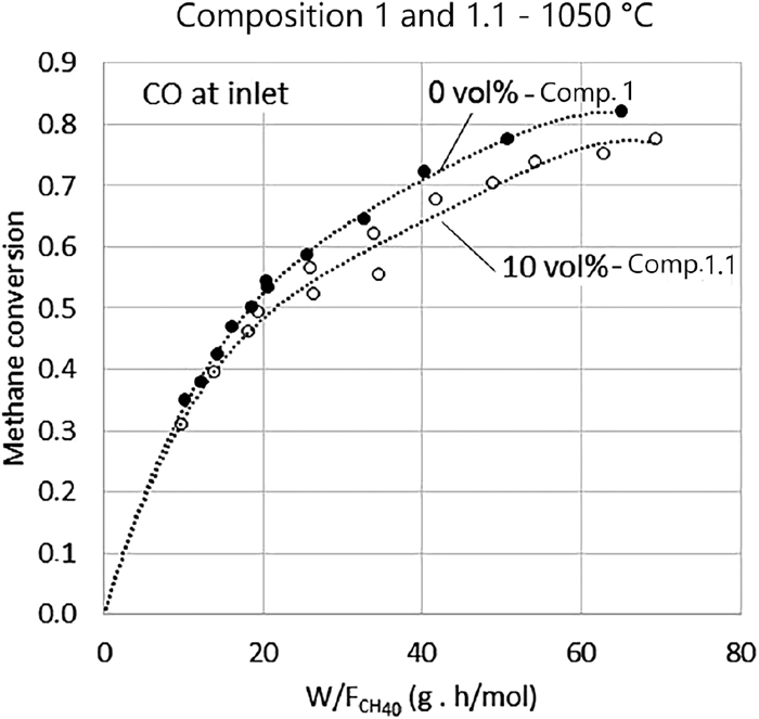
Tests with the presence of CO in the inlet gas were performed to evaluate the hypothesis that its presence would reduce the rate of the reforming reaction, which could explain the behavior of the data in higher conversions (X > 0.75) of methane. At this stage, the reaction rate is much smaller since the slope of conversion curves in Fig. 6 are less steep. A possible mechanism would be that the presence of CO in the atmosphere would reduce the rate of desorption of the molecules of the same gas formed on the surface of the catalyst. For the experiments with Composition 1, when methane conversion reached levels above 0.75, the concentration of CO in the outlet gas was approximately 9 vol.%. For this reason, 10 vol.% CO was added in Composition 1, yielding Composition 1.1, shown in Table 2.
The test was conducted at 1050°C with 25 g, and 50 g of sponge iron and inlet gas flow rates ranging from 2.5 L/min and 8.0 L/min. The results of these tests are shown in Fig. 7. The difference in the tendency of the two curves (with and without CO) is relatively small. If the adsorption of CO was lowering the reaction rate, then the initial rate of methane reforming with Composition 1.1 would be lower than the rate of Composition 1 at all conversions. Since the slope of the curve near the origin is similar for both Composition 1.1 and Composition 1, it was concluded that the presence of 10 vol% of CO does not significantly alter the conversion rate. The observed smaller reaction rate may be caused by the lower amount of methane in Composition 1.1 in comparison to Composition 1, as showed in Table 2.
Finally, experiments were performed with composition 3, which is the composition of the Hyl/Energiron Zero Reformer process. This composition has a thermodynamic potential for carburizing iron, as shown in the equilibrium diagram of Fig. 1. Obtained results were different from those of the other two compositions. Concentration of CO and CO2 in the off gases were very similar, regardless of W/FCH40 ratio levels. Besides, the mass of the system increased over time, indicating deposition of material in the sponge iron.
Due to these results, interrupted tests were performed to analyze the carbon content of the samples. Carbon contents are shown in Figure 8, which presents the results of tests conducted with 25 g and 50 g of sponge iron at 1050°C with inlet gas flow rates of 5 L/min and 10 L/min. The results show that carburizing was intense with carbon content reaching more than 15 wt.% with 45 minutes of reaction. Table 4 shows the amount of injected methane that is converted into deposited carbon during interrupted experiments with composition 3. This is calculated by the ratio between the rate of carbon injected as methane (
(
m
˙
C
)
C
H
4
) and the carburizing rate (
m
˙
C
) obtained from the slope of the curves presented in Fig. 8. Results show that 17% to 52% of the injected methane in the inlet gas is converted in deposited carbon, depending on the inlet flow and mass of sponge iron. The change in the inlet flow rate from 5 L/min to 10 L/min did not result in a significant change in the carburizing rate.

Table 4. Amount of methane that is converted in deposited carbon during experiments with composition 3 at 1050°C.
Inlet flow rate
(L/min) | Mass of sponge iron
(g) | Rate of carbon
injected as
methane
(
m
˙
C
)
C
H
4
(g/min)* | Carburizing rate
m
˙
C
(g/min)** |
m
˙
C
(
m
˙
C
)
C
H
4
|
|---|
| 5 | 25 | 0.375 | 0.106 | 28% |
| 10 | 25 | 0.750 | 0.125 | 17% |
| 5 | 50 | 0.375 | 0.194 | 52% |
| 10 | 50 | 0.750 | 0.261 | 35% |
* Calculated from inlet flow rate of methane.
** Obtained from slopes of curves in
Fig. 8.
Figure 9 presents an image of the scanning electron microscope (SEM) of the polished cross-section of a sponge iron particle resulting from the experiment with composition 3, inlet flow rate of 5.0 L/min, and 25 g sponge iron. The carbon content of this sample is 19.2 wt.%. Energy-dispersive X-ray spectroscopy (EDS) analysis shows that the matrix (point 1) is composed mainly of iron. Moreover, there is a second phase adhered on the surface of iron particles. This adhered phase (point 2) has a high carbon content and formed as a result of methane decomposition on the inner surface of pores of sponge iron particles. Virtually all surface of iron particles is covered with this second phase, which hinders the catalytic activity of sponge iron for reforming reaction. The iron found in this carbon-rich phase might be the result of interference of neighboring phases since the layer of the carbon-rich phase has a thickness of lower than 10 μm. This thick layer of carbon was not present in sponge iron after reduction, as showed in Fig. 4.

The mechanism of the reforming reaction with composition 3 is no longer the one proposed by Münster and Grabke,9,10) and becomes the reaction of steam with solid carbon deposited on the sponge iron, according to reaction represented by the Eq. (11). The change in reaction mechanism is a result of the high level of carbon deposition that caused the coverage of the pore surface area of the sponge iron with solid carbon. Therefore, gas species cannot interact with the iron surface, and catalytic activity is null.
In the industrial reactor, the carburizing rate of sponge iron is expected to be lower than observed in this study, since the pressure in the zone of injection of the reduction gas can reach 8 bar, which displaces the equilibrium of the methane decomposition reaction (Eq. (12)) towards the reagents. That procedure difference should promote a lower carburization rate, nevertheless this needs to be confirmed in future investigations.
|
C (s)+
H
2
O (g)=CO (g)+
H
2
(g)
| (11) |
|
C
H
4
(g)=C (s)+2
H
2
(g)
| (12) |
5. Conclusions
Methane reforming experiments were performed with sponge iron as a catalyst. The used gas mixtures were composed of H2, H2O, CH4, CO, and Ar. System temperatures varied between 875°C and 1050°C and total pressure was 1 atm. The obtained results showed that:
• Sponge iron acts as a catalyst and it was possible to obtain methane conversions up to 87% due to steam reforming at 1050°C.
• The conversion of methane by the reforming reaction increased at higher temperatures.
• Inlet gas with higher H2/H2O ratio resulted in higher methane conversions and higher reaction rates.
• The presence of CO in the gas mixtures had not a significant effect on methane conversions, which indicates that the desorption of this species is not a rate-controlling step.
• The use of the inlet gas with a composition like that of the Energiron Zero Reforming process, led to the intense carburization of sponge iron, consuming from 17% up to 52% of the injected methane. The performance of sponge iron as a catalyst was compromised for the reforming reaction so that the CO and H2 generation started to occur through the interaction of water vapor with deposited solid carbon.
Acknowledgments
The authors would like to thank the GASFERROSIL project (grant number: 224950/E30) financed by the Research Council of Norway and FIPT (The Foundation for the Support of the Institute for Technological Research) for supporting this project.
References
- 1) Midrex Technologies: 2017 World Direct Reduction Statistics, https://www.midrex.com/wp-content/uploads/MidrexStatsBook2017.5_.24_.18_.pdf, (accessed 2018-10-15).
- 2) A. Ajbar, K. Alhumaizi and M. Soliman: Korean J. Chem. Eng., 28 (2011), 2242.
- 3) J. R. Rostrup-Nielsen and L. J. Christiansen: Concepts in Syngas Manufacture, ed. by G. J. Hutchings, Imperial College Press, London, (2011), 241.
- 4) M. E. S. Hegarty, A. M. O’Connor and J. R. H. Ross: Catal. Today, 42 (1998), 225.
- 5) W. W. Akers and D. Camp: AIChE J., 1 (1955), 471.
- 6) J. P. Van Hook: Catal. Rev. Sci. Eng., 21 (1980), 1.
- 7) N. M. Bodrov, L. O. Apel’baum and M. I. Temkin: Kinet. Catal., 5 (1964), 614.
- 8) D. L. Trimm: Catal. Today, 37 (1997), 233.
- 9) P. Münster and H. J. Grabke: Ber. Bunsenges. Phys. Chem., 84 (1980), 1068. http://doi.wiley.com/10.1002/bbpc.19800841029
- 10) P. Münster and H. J. Grabke: J. Catal., 72 (1981), 279.
- 11) H. J. Grabke: Metall. Trans., 1 (1970), 2972.
- 12) E. T. Turkdogan and J. V. Vinters: Metall. Trans., 2 (1971), 3175.
- 13) N. Towhidi and J. Szekely: Ironmaking Steelmaking, 8 (1981), 237.
- 14) M. Ishigaki, R. Takahashi and Y. Takahashi: Bull. Res. Inst. Miner. Dress. Metall. Tohoku Univ., 38 (1982), 35.
- 15) R. Takahashi, Y. Takahashi, J. Yagi and Y. Omori: Trans. Iron Steel Inst. Jpn., 26 (1986), 765.
- 16) A. A. El-Geassy, K. A. Shehata and S. Y. Ezz: Trans. Iron Steel Inst. Jpn., 17 (1977), 629.
- 17) M.-H. Bai, H. Long, S.-B. Ren, D. Liu and C.-F. Zhao: ISIJ Int., 58 (2018), 1034.
- 18) H. J. Grabke, E. M. Müller-Lorenz and A. Schneider: ISIJ Int., 41 (2001), S1.
- 19) O. Ostrovski and G. Zhang: AIChE J., 52 (2006), 300.
- 20) Y. He and P. C. Pistorius: Metall. Mater. Trans. B, 47 (2016), 1538.
- 21) J. Zhang and O. Ostrovski: ISIJ Int., 41 (2001), 333.
- 22) Y. Iguchi, S. Sawai and K. Ohiwa: Metall. Mater. Trans. B, 32 (2001), 1161.
- 23) Y. Iguchi, K. Hori-I, T. Shibata and S. Hayashi: ISIJ Int., 44 (2004), 984.
- 24) Y. Iguchi, K. Hori-I and T. Shibata: ISIJ Int., 44 (2004), 992.
- 25) S. Hayashi and Y. Iguchi: ISIJ Int., 38 (1998), 1053.
- 26) K. Nishihiro, T. Maeda, K. Ohno and K. Kunitomo: ISIJ Int., 59 (2019), 634.
- 27) O. G. Dam G. and H. R. Bueno C.: Method and Apparatus for the Direct Reduction of Iron, CA, CIPO, CA1336359, (1988).
- 28) M. Jampani: Ph.D. thesis, Carnegie Mellon University, (2016), http://repository.cmu.edu/dissertations/851, (accessed 2020-04-20).
- 29) M. Jampani, J. Gibson and P. C. Pistorius: Metall. Mater. Trans. B, 50 (2019), 1290.
- 30) H. S. Fogler: Elements of Chemical Reaction Engineering, Pearson Education, London, (2016), 957.


