Abstract
The effect of ammonium thiocyanate (NH4SCN) on the behavior of hydrogen entry into low alloy steel under cathode charging was investigated using electrochemical hydrogen permeation technique. In this study, hydrogen entry sides were polarized galvanostatically to control the rate of hydrogen evolution reaction. The potential, hydrogen charging current density and hydrogen permeation current density were measured at pH of 3.0 in acetic buffer solution with and without 3 g·L−1 NH4SCN. From the Tafel slope of the cathode reaction and the dependence of hydrogen concentration on hydrogen charging current density, it was confirmed that the hydrogen evolution reaction proceeds under Volmer-Tafel mechanism in this study. NH4SCN drastically increased hydrogen entry into steel. To analyze the results of this study, the efficiency of hydrogen entry was calculated from the relationship among hydrogen charging current density, hydrogen permeation current density and hydrogen overpotential. It was found that the hydrogen entry efficiency was drastically higher in NH4SCN environment than that in NH4SCN free environment. However, the coverage of adsorbed hydrogen atoms on hydrogen entry side decreased in NH4SCN environment. To discuss the mechanism that NH4SCN increases hydrogen entry efficiency, the activation energies of hydrogen adsorption and hydrogen absorption were estimated by temperature dependence of the hydrogen charging current density and the hydrogen permeation current density. It is suggested that NH4SCN increased the activation energy of hydrogen adsorption although it decreased that of hydrogen absorption.
1. Introduction
Thiocyanate ion, SCN−, is a kind of hydrogen entry catalysts called poison which accelerate hydrogen entry into steel. Especially, ammonium thiocyanate, NH4SCN, is widely used as poison because of its ease to treat and large acceleration effect of hydrogen entry into steel, for example, FIP test (Fèdèration Internationale de la Prècontrainte).1)
The mechanisms that poisons accelerate hydrogen entry have been reported a lot so far. Those are mainly categorized in two theories.2) One is the mechanism that poisons suppress the recombination of hydrogen atom on the steel surface and increase hydrogen coverage. The other is the mechanism that they decrease the binding energy between hydrogen atom and metal. For example, Ando et al.3) reported that hydrogen entry acceleration due to adding sulfur, cyanide and arsenic was caused by the increase of the coverage of adsorbed hydrogen atoms on a metal surface. On the other hand, Bockris et al.4) reported that hydrogen catalysts lower the binding energy of metal and absorbed hydrogen atoms; therefore, they accelerate hydrogen entry into steel. Regarding the mechanism of lowering energy, they considered three possible theories;4) 1) the electrochemical interaction between hydrogen entry catalysts and hydride ion H−, 2) the interaction between hydrogen entry catalysts and the d-bond orbital of the metal, and 3) the preferential adsorption of hydrogen entry catalysts at sites favorable for hydrogen evolution. However, the mechanism that the catalysts accelerate hydrogen entry into steel has not been elucidated yet.
A number of studies about the effects of SCN− on hydrogen entry and corrosion behavior have been reported so far. Ichiba et al.5) measured the corrosion rate and the polarization curves of steel bars for prestressed concrete in 0–20 mass% NH4SCN solution. They reported that NH4SCN increased the cathodic current and the corrosion rate. On the other hand, Marshakov et al. measured the polarization curves of carbon steel at pH of 1.3 in 0.5 M Na2SO4 + 0.25 M H2SO4 solution with 20 mmol·L−1 KSCN. They reported that SCN− decreased the cathodic current and the anodic current. The reason why the effect of SCN− on the electrochemical behavior and the corrosion rate are different has not been clarified.
The effect that SCN− accelerate hydrogen entry into steel is widely known. Marshakov et al.6) pointed out that SCN− increased hydrogen entry efficiency by using Iyer Pickering Zamanzadeh (IPZ) analysis.7)
From Fig. 1, the hydrogen evolution reaction (HER) consists of three elementary processes expressed as Reactions (1), (2) and (3).
|
H
+
+e→H
ad
(I. Volmer reaction)
| (1) |
|
H
ad
+
H
ad
→
H
2
(II. Tafel reaction)
| (2) |
|
H
ad
+
H
+
+e→
H
2
(III. Heyrovsky reaction)
| (3) |
where H
ad refers to the adsorbed hydrogen atom on the metal surface. At first, hydrogen ion is discharged onto the metal surface whereon it is adsorbed. Following that, the adsorbed hydrogen atoms form hydrogen molecules, and leave the metal surface. It is considered to be dependent on the electrode potential and/or environmental factors where the HER proceeds by discharge-recombination mechanism called Volmer–Tafel mechanism (Reaction (1)→Reaction (2)) or discharge-electrochemical mechanism called Volmer–Heyrovski mechanism (Reaction (1)→Reaction (3)).
2) Simultaneously, some of the adsorbed hydrogen atoms are absorbed into steel. These absorbed hydrogen atoms cause hydrogen embrittlement.
The subject of this study is to clarify the effects of SCN− on above elemental reactions of the hydrogen entry process. That is, it is to verify whether SCN− suppresses the recombination of hydrogen atom and then increases hydrogen coverage, or it lowers the binding energy of metal and hydrogen atoms. The electrochemical hydrogen permeation technique was performed under galvanostatic cathode charging to evaluate the effect of NH4SCN on the hydrogen entry behavior. IPZ analysis was conducted based on the test results to evaluate the hydrogen entry efficiency.
2. Experimental Procedure
2.1. Material
The chemical composition of the material used in this study is indicated in Table 1. The slab of which dimension was 250 mm length, 300 mm width and 300 mm thickness was melted in a production mill and rolled to 32 mm thick plate in thermo-mechanical control process in a laboratory. Acicular ferrite was mainly observed at quarter-thickness as shown in Fig. 2. ASTM A370 tensile test specimens with the diameter of 12.5 mm were taken from the center portion of the plate. The yield strength (YS) of the material was 429 MPa, and the tensile strength (TS) was 539 MPa, respectively.
Table 1. Chemical compositions of tested specimen (mass%).
| C | Si | Mn | Others | Fe |
|---|
| 0.05 | 0.24 | 1.37 | Cr, Ni, Cu, Nb, Ti | Bal. |
The electrochemical hydrogen permeation test specimens were taken from the plate at quarter-thickness. The dimension of these specimens was 40 mm length, 40 mm width and 1 mm thickness. The surface of these specimens was machined and electro-polished by 20 μm to remove the deformed surface layer. Simultaneously, the polarization test specimens were taken from the plate at quarter-thickness. The dimension of these specimens was 15 mm diameter and 2 mm thickness. The test surface was machined and polished in #600 by SiC paper.
2.2. Polarization Measurement
A test solution was 1 mol·L−1 acetic buffer solution of pH 3.0 containing 5.0% NaCl with and without 3 g·L−1 NH4SCN. The solution was deaerated by N2 gas. Pt counter electrode and saturated Ag/AgCl reference electrode (SSE) were employed. Schematic drawing of the test apparatus was shown in Fig. 3. The specimen was set into the specimen holder as the working electrode. At first, the specimen was immersed in the test solution, and open circuit potential (OCP) was measured for 600 s, and then the potential was swept toward cathodic direction until −1.1 V vs. SSE. After OCP was measured again for 600 s, the potential was swept toward anodic direction until −0.3 V vs. SSE. The sweep rate of the potential in this test was 20 mV·min−1. Measured current was divided by test area (1 cm2) to obtain current density.
2.3. Electrochemical Hydrogen Permeation Technique
For the electrochemical hydrogen permeation test, the Devanathan-Stachursky type cell8) was used. Schematic drawing of the test cell is shown in Fig. 4. Electrolytic Ni plating was performed on the specimen surface facing the hydrogen withdrawal side as described below. A Watt bath9) (NiCl2: 4.5 × 10⁻² kg·L−1, NiSO4: 0.24 kg·L−1, H3BO3: 3.0 × 10⁻² kg·L−1) and a Ni plate as counter electrode were employed for the plating. A current density of 10 A·m2 was applied to the specimen for 600 s at 303 ± 3 K. The estimated thickness of the plating layer was 0.2 μm.

In the electrochemical hydrogen permeation test, the specimen was set between two cells. Then, hydrogen was charged using cathodic charging on the hydrogen entry side (left-side cell in Fig. 4). Some of the adsorbed hydrogen atoms on the hydrogen entry side are absorbed into steel and diffuse toward the hydrogen withdrawal side (right-side cell in Fig. 4). As soon as the hydrogen atom reaches the hydrogen withdrawal side, it is oxidized into a hydrogen ion. This oxidation current was measured as the hydrogen permeation current which was dependent on the flux of permeated hydrogen through the specimen.
The test solution in the hydrogen entry side cell was 1 mol·L−1 acetic buffer solution of pH 3.0 containing 5.0% NaCl with and without 3 g·L−1 NH4SCN. The solution was deaerated in N2 gas. Pt counter electrode and saturated Ag/AgCl reference electrode were employed. The test solution in the hydrogen withdrawal side cell was 0.1 N NaOH solution.
Procedure of the test is described below. At first, NaOH solution was introduced to the hydrogen withdrawal side cell and + 0.148 V vs. SSE was applied on the hydrogen withdrawal side. Before starting hydrogen charging, passivation current was decreased to 5 × 10⁻³ A·m−2 or lower, and then the test solution was introduced to the hydrogen entry side cell without exposing to the air. The test solution was prepared in the other glass vessel in advance. Following the introduction, a galvanostatic current density was immediately applied on the hydrogen entry side. The current density of −1 mA·cm−2 was applied first for 1.8 × 10⁴ s (5 h) to saturate trap sites in the specimen with hydrogen. Thereafter, stepwise charging current density was applied, and the potential of hydrogen entry side was measured. The range of charging current density was from −10 to −0.1 mA·cm−2. The duration of application of each current density was 1.08 × 10⁴ s (3 h) to stabilize the hydrogen permeation current and the potential of hydrogen entry side. Schematic drawing of the time dependence of current densities and potentials on entry and withdrawal sides are shown in Fig. 5. In addition, hydrogen diffusion coefficient of the material was measured by the build-up and decay method.10) The test solution and the electrodes were same as described before. The potential of −0.85 V vs. SSE and −1.15 V vs. SSE were applied on the hydrogen entry surface. The duration of application of each current density was 7.2 × 10³ s (2 h). The response of the hydrogen permeation current to the applied potential on the hydrogen entry surface was analyzed using Fick’s second law. The build-up and the decay curves were measured five times, respectively, and an average value of the hydrogen diffusion coefficient of them was calculated as 2 × 10⁻⁹ m2·s−1.

The activation energy of hydrogen adsorption was estimated by temperature dependence of the hydrogen charging current density. The test solution was 1 mol·L−1 acetic buffer solution of pH 3.0 containing 5.0% NaCl with and without 3 g·L−1 NH4SCN. Pt counter electrode and saturated Ag/AgCl reference electrode (SSE) were employed. Firstly, a potentionstatic charging of −0.7 V vs. SSE was applied on the specimen for 7.2 × 10³ s (2 h) and then the current density was measured. The range of the temperature of the test solution was from 280 to 318 K.
The activation energy of hydrogen absorption was also estimated by temperature dependence of the hydrogen permeation current density. The test solution in the hydrogen entry side and the hydrogen withdrawal side, the counter electrode and the reference electrode were same as the electrochemical hydrogen permeation technique. A galvanostatic charging of −100 μA·cm−2 was applied on the hydrogen entry side for 7.2 × 10³ s (2 h) and then the hydrogen permeation current density was measured. The range of the temperature of the test solution was from 288 to 313 K.
The activation energies of hydrogen adsorption and hydrogen absorption were estimated by temperature dependence of the hydrogen charging current density and the hydrogen permeation current density. A theoretical explanation is described below. From Arrhenius equation, the rate constant k is described as
where
A is frequency factor,
Ea is the activation energy,
R is gas constant, and
T is temperature. Taking logarithms of
Eq. (4),
Eq. (5) is derived as follows:
|
lnk=-
E
a
R
⋅
1
T
+lnA
| (5) |
represents ln
k is linear to the inverse number of temperature, and the activation energy is obtained from the slope of the line.
A current density i is represented as
|
i=F ka=FaA⋅exp(
-
E
a
RT
)
| (6) |
where
F is Faraday constant, and
a is activity. So, the activation energies of hydrogen adsorption and hydrogen absorption were estimated by temperature dependence of the hydrogen charging current density and the hydrogen permeation current density.
2.5. Theoretical Explanation of IPZ Analysis
IPZ analysis was adopted to analyze the effect of NH4SCN on the hydrogen entry behavior. Schematic drawing of the hydrogen permeation process of the employed technique is shown in Fig. 6. Profile of the hydrogen atom concentration in a steady state is represented as a bold solid line too. Firstly, the hydrogen ions in the hydrogen entry side cell are reduced to the hydrogen atoms on the metal surface. In the experiments, the reduction rate of hydrogen ion was controlled by the hydrogen charging current because of galvanostatically-charging. Almost all adsorbed hydrogen atoms form hydrogen molecules, and leave the metal surface. However, some of the adsorbed hydrogen atoms are absorbed into steel. These absorbed hydrogen atoms diffuse toward the hydrogen withdrawal side. The driving force of the diffusion is the concentration gradient of hydrogen atom in the specimen thickness.

Because the applied potential on the hydrogen withdrawal side is noble enough for hydrogen oxidation, the hydrogen atom is oxidized to the hydrogen ion immediately upon reaching hydrogen withdrawal side. The hydrogen oxidation current is measured as the hydrogen permeation current. The hydrogen concentration profile from the hydrogen entry side to the hydrogen withdrawal side becomes straight under an ideal steady state as indicated in Fig. 6. The IPZ analysis is based on the following hypotheses:2,11) i) HER proceeds by discharge-recombination mechanism (Reaction (1)→Reaction (2)); ii) Hydrogen discharge reaction and hydrogen recombination reaction are so fast that the inverse reactions of them are negligible; iii)The hydrogen recombination reaction is not the rate determining step (RDS); and iv)The hydrogen absorption reaction (Had→Hab) and its inverse reaction (Hab→Had) are in local equilibrium with each other in the hydrogen entry surface.
As shown in Fig. 6, the hydrogen permeation current density is represented as the difference between the reaction rate of the hydrogen absorption reaction (Had→Hab) and its inverse reaction (Hab→Had).
|
J=F (
k
abs
θ-
k
ads
C
0
)
| (7) |
, where
kabs and
kads are the rate constants of the hydrogen absorption reaction and its inverse reaction, respectively,
θ is the coverage of hydrogen atom on the hydrogen entry surface, and
C0 is the hydrogen concentration under the hydrogen entry surface. Applying Fick’s first law,
C0 is proportional to the hydrogen permeation current under an ideal steady state.
where
L is the specimen thickness and
DH is the hydrogen diffusion coefficient.
Equation (9) is derived using Eqs. (7) and (8).
|
k
ads
+
D
H
L
k
abs
=
θ
C
0
(
=
1
k
″
)
| (9) |
The right-hand side of
Eq. (9) represents the ratio of the hydrogen coverage to the hydrogen concentration under the hydrogen entry surface. The
k″ value is an inverse number of the right-hand side. In this paper,
k″ is defined as the hydrogen entry efficiency. According to
Eq. (9), if the coverage of adsorbed hydrogen atom is constant, hydrogen entry behavior depends on the
k″ value.
Based on hypothesis ii), the hydrogen charging current density ic can be represented as given in Eq. (10).
|
i
c
=
i
0
(1-θ)exp(
-
αηF
RT
)
| (10) |
where
i0 is the exchange current density,
α is the transfer coefficient, and
η is the hydrogen overpotential.
Equation (11) is obtained using
Eqs. (8),
(9) and
(10).
|
i
c
exp(
αηF
RT
)
=-
b
i
0
k
″
J+
i
0
| (11) |
where
Equation (11) indicates that a linear relationship between hydrogen permeation current density and
icexp(
αF
η/RT) should be obtained. The
k″ value is calculated using the slope of
Eq. (11). In this test, the
k″ value is not affected by the temperature dependence of the hydrogen diffusion coefficient, because the test temperature is constant.
3. Results
3.1. Effect of NH4SCN on Polarization Curve
Polarization curves in each environment were shown in Fig. 7. The corrosion potential Ecorr in 3 g·L−1 NH4SCN environment was less noble by about 0.1 V as compared with that in NH4SCN free environment. NH4SCN decreased the cathodic current and increased anodic current. To estimate Tafel slope of the anodic and cathodic reactions, a tangent line was drawn on the polarization curve where the potential range was from 0.06 V to 0.16 V from Ecorr. The Tafel slope of cathodic reaction were −0.123 V·decade−1 in NH4SCN environment, and −0.134 V·decade−1 in NH4SCN free environment, respectively. The Tafel slope of anodic reaction were 0.118 V·decade−1 in NH4SCN environment, and 0.108 V·decade−1 in NH4SCN free environment, respectively.
3.2. Relationship between Hydrogen Charging Current and Hydrogen Permeation Current
The relationship between hydrogen permeation current density and square root of the hydrogen charging current density obtained in each environment are shown in Fig. 8. Linear relationship can be observed in both environments. The slope of the line is about 25 times steeper in NH4SCN environment than that in NH4SCN free environment. Although the hydrogen charging current density are same, which means that the reduction rates of hydrogen ions are equivalent, the hydrogen permeation current density increases in NH4SCN environment, as compared with NH4SCN free environment as exhibited in Fig. 8.
4. Discussion
4.1. Estimation of Hydrogen Evolution Reaction
From Fig. 7, NH4SCN decreased the cathodic current, and the Tafel slopes of cathodic reaction were about −0.120 V·decade−1 in acidic condition of pH 3.0. Therefore, it was considered that the dominant cathodic reaction in this study was hydrogen evolution reaction, not reduction of SCN− in Ichiba’s5) study. To determine the mechanism of HER, the Tafel slope or the dependence of surface hydrogen concentration on hydrogen charging current should be obtained.12) Table 2 showed parameters to verify the mechanism of HER in acidic condition, as a reference. The dependence of surface hydrogen concentration on hydrogen charging current in this study is shown in Fig. 9. The slope of lines in each environment was 0.55. Referring to Table 2, it is suggested that HER proceeds under Volmer (RDS)-Tafel or Volmer-Tafel (Coupled), where RDS is rate determining step, coupled means the mixed rate control both Volmer reaction and Tafel reaction. Since the assumption 1) of IPZ model was satisfied in this study, this model was adapted to the results to analyze the hydrogen entry efficiency.
Table 2. Characteristics of various mechanisms of hydrogen evolution reaction in acidic solution.
| H2 evolution reaction |
(
∂η
∂ log i
)
pH
mV/decade |
(
∂ log i
∂pH
)
η
|
∂ log
C
0
∂ log i
|
∂ η
∂ log
C
0
mV/decade |
∂ log
C
0
∂pH
|
|---|
| Volmer (RDS)→ Tafel | −120 | −1 | 0.5 | −240 | −0.5 |
| Volmer → Tafel (RDS) | −30 | −2 | 0.5 | −60 | −1 |
| Volmer (RDS) → Heyrovsky | −120 | −1 | 1 | − | 0 |
| Volmer → Heyrovsky (RDS) | −40 | −2 | 1 | −60 | −1 |
| Volmer → Tafel (Coupled) | −120 | −1 | 0.5 | −240 | −0.5 |
| Volmer → Heyrovsky (Coupled) | −120 | −1 | 1 | ∞ | 0 |
The hydrogen charging current density, the hydrogen permeation current density and the hydrogen overpotential obtained in this study were substituted into Eq. (11). The relationship between the electrochemical parameter icexp(αFη/RT) and the hydrogen permeation current density is shown in Fig. 10. The electrochemical parameter ic exp(αFη/RT) was calculated using a value of α = 0.5.13) Figure 10 exhibited a linear relationship between ic exp(αFη/RT) and the hydrogen permeation current density in both environments. The slope of the line is steeper in NH4SCN free environment than that in NH4SCN environment. From Eq. (11), the hydrogen entry efficiency k″(= C0/θ) calculated from the slope of the line was 0.79 mol·m−3 and 22 mol·m−3 for NH4SCN and NH4SCN free environments, respectively. Thus, NH4SCN increased the hydrogen entry efficiency drastically.
4.3. Effect of NH4SCN on Coverage of Absorbed Hydrogen Atom
From Eqs. (8) and (9), the coverage of adsorbed hydrogen atom θ can be calculated by hydrogen concentration and the hydrogen entry efficiency. The relationship between the hydrogen overpotential and the coverage of hydrogen atom on the hydrogen entry surface is shown in Fig. 11. In this study, the hydrogen overpotential was defined as the potential difference between the potential of working electrode and the equilibrium potential of the hydrogen discharge reaction, and it represents the driving force of the hydrogen discharge reaction on the hydrogen entry side. Thus, as the absolute value of the hydrogen overpotential increases, the driving force of the hydrogen discharge reaction becomes greater. As shown in Fig. 11, as the absolute value of the hydrogen overpotential increases, the coverage of hydrogen atoms also increases. Although the hydrogen overpotential is equivalent, the coverage of hydrogen atoms in NH4SCN was lower than that in NH4SCN free environment. Therefore, in this test environment, the mechanism to accelerate hydrogen entry into steel by increasing the hydrogen coverage due to adding poisons could not be adapted.

Figure 12 shows Arrhenius plot of the current density under potentiostatic polarization of −0.7 V vs. SSE. The purpose applying potentiostatic polarization is to keep the hydrogen overpotential constant, which is the driving force of the hydrogen discharge reaction. Arrhenius plots in both environments showed a linear relationship, and the slope of the line is steeper in NH4SCN environment than that in NH4SCN free environment. The activation energies of hydrogen adsorption calculated from these slopes were 43 × 103 J·mol−1 and 31 × 103 J·mol−1 in NH4SCN and NH4SCN free environment, respectively. Therefore, NH4SCN increased the activation energy of hydrogen adsorption, and it was suggested that hydrogen adsorption is suppressed in NH4SCN environment.

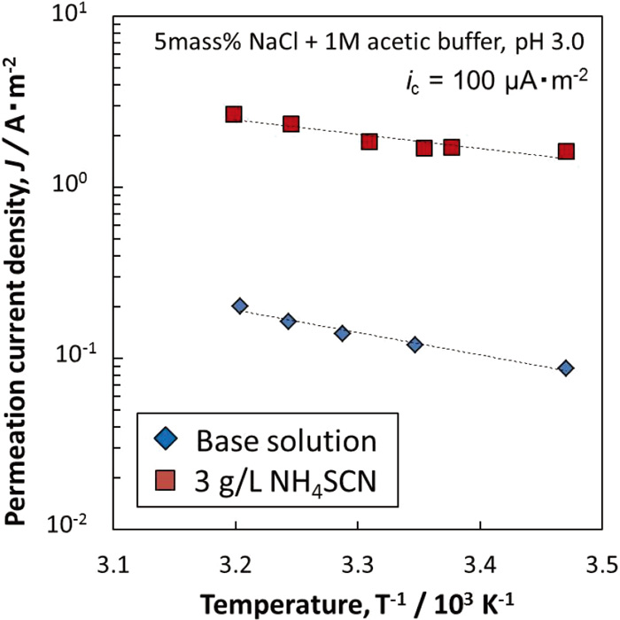
Figure 13 shows Arrhenius plot of the hydrogen permeation current density under galvanostatic charging of −100 μA·cm−2. The purpose applying the galvanostatic charging is to keep the amount of adsorbed hydrogen atoms on the hydrogen entry surface constant. Arrhenius plots in both environments showed a linear relationship, and the slope of the line is steeper in NH4SCN free environment than that in NH4SCN environment. The activation energies calculated from the slopes were 16 × 103 J·mol−1 and 25 × 103 J·mol−1 in NH4SCN and NH4SCN free environment, respectively. However, the activation energy obtained in Fig. 13 is that of a series of hydrogen permeation process. It contains absorption of hydrogen atoms and its reverse reaction on the hydrogen entry surface, and also contains diffusion of hydrogen atoms in the specimen, and hydrogen oxidation on the hydrogen withdrawal surface. In this study, all the test conditions except for the test solution with and without NH4SCN are unified, so it is thought that the difference of this activation energy is mainly affected by the change of the activation energy of hydrogen absorption with and without NH4SCN. Therefore, NH4SCN decreased the activation energy of hydrogen absorption, and it was suggested that hydrogen absorption is accelerated in NH4SCN environment.
Equation (13) is derived using Eqs. (7), (8) and (9).
|
J=
F
D
H
θ
L
⋅
k
abs
k
ads
+
D
H
L
=
F
D
H
θ
L
⋅
k
″
| (13) |
In this study, the hydrogen entry side was charged galvanostatically to keep the coverage of adsorbed hydrogen atom. Therefore, from
Eq. (13), the hydrogen entry efficiency relates with the hydrogen permeation current density. From
Fig. 13, the hydrogen permeation current density is described as
Eq. (14).
|
J=
A
′
⋅exp(
-
E
a
RT
)
| (14) |
where
A′ is the frequency factor. From
Eqs. (13) and
(14), it is suggested that as the activation energy of hydrogen entry decrease, the hydrogen permeation current density
J and the hydrogen entry efficiency
k″ increase.
4.5. Mechanism for Accelerating of Hydrogen Entry by NH4SCN
As shown in Fig. 11, the mechanism that NH4SCN accelerates hydrogen entry could not be explained by the mechanism for suppressing the recombination of hydrogen atom and increasing hydrogen coverage. In this section, the mechanism that NH4SCN change the activation energies of hydrogen adsorption and absorption was discussed from the viewpoint of the binding energy of metal and absorbed hydrogen atoms. The schematic drawings of the potential energies of H+, Had and Hab were shown in Fig. 14. If NH4SCN lowers the binding energy of metal and adsorbed hydrogen atoms,4) it is thought that the potential energy of the adsorbed hydrogen atom increased from dotted line to solid line in Fig. 14. In this case, the activation energy of hydrogen adsorption reaction (H+→Had) increases from line ① to line ①’ in Fig. 14. As a result, hydrogen adsorption is suppressed. This mechanism is supported by those results that NH4SCN decreased cathode current as shown in Fig. 7, and that the coverage of hydrogen atoms in NH4SCN was lower than that in NH4SCN free environment as shown in Fig. 11. On the other hand, the activation energy of hydrogen absorption reaction (Had→Hab) decreases from line ② to line ②’ in Fig. 14. As a result, hydrogen absorption is accelerated. This is supported by the result that NH4SCN increased the hydrogen entry efficiency calculated using IPZ analysis as shown in Fig. 10. Therefore, in this study, NH4SCN suppressed hydrogen adsorption and lowered the coverage of adsorbed hydrogen atom. As these results, it is suggested that NH4SCN increased hydrogen entry efficiency and accelerated hydrogen entry into steel. To clarify the mechanism that NH4SCN lowers the binding energy of metal and adsorbed hydrogen atoms and increases the potential energy of the adsorbed hydrogen atom is our future work.

5. Conclusion
At a pH of 3.0 in acetic buffer solutions, the electrochemical hydrogen permeation technique was performed under galvanostatic cathode charging to evaluate the effect of NH4SCN on the hydrogen entry behavior. IPZ analysis was applied to the test results to evaluate the hydrogen entry efficiency. Furthermore, the activation energies of hydrogen adsorption and absorption were measured from the temperature dependence of the hydrogen charging current and the hydrogen permeation current. The following results were obtained:
(1) The corrosion potential was less noble in NH4SCN environment as compared with that in NH4SCN free environment. NH4SCN decreased the cathodic current and increased anodic current.
(2) The hydrogen permeation current density in 3 g·L−1 NH4SCN environment was about 25 times higher than that in NH4SCN free environment although the hydrogen charging current density was the same in both environments.
(3) The hydrogen permeation current was linear to the square root of the hydrogen charging current with and without NH4SCN.
(4) From Arrhenius plot, NH4SCN increased the activation energy of hydrogen adsorption and decreased that of hydrogen absorption.
(5) From IPZ analysis, NH4SCN decreased the hydrogen surface coverage, however it increased the hydrogen entry efficiency which represented the ratio of the hydrogen concentration to the hydrogen coverage on the hydrogen entry surface. As the activation energy of hydrogen entry decreased, the hydrogen permeation current density and the hydrogen entry efficiency increased.
References
- 1) FIP WG: Report on Prestressing Steel: 5. Stress Corrosion Cracking Resistance Test for Prestressing Tendons, Technical Report, FIP, Paris, (1980).
- 2) M. Nagumo: Zairyo-to-Kankyo, 55 (2006), 380 (in Japanese). https://doi.org/10.3323/jcorr.55.380
- 3) S. Ando and K. Yamakawa: Proc. Annual Meeting of JSME/MMD, 1991-A, Japan Society of Mechanical Engineers, Tokyo, (1991), 473 (in Japanese).
- 4) J. O’M. Bockris, J. McBreen and L. Nanis: J. Electrochem. Soc., 112 (1965), 1025. https://doi.org/10.1149/1.2423335
- 5) M. Ichiba, K. Takai and J. Sakai: ISIJ Int., 56 (2016), 397. https://doi.org/10.2355/isijinternational.ISIJINT-2015-288
- 6) A. I. Marshakov and T. A. Nenasheva: Prot. Met., 37 (2001), 543. https://doi.org/10.1023/A:1012811428981
- 7) R. N. Iyer, H. W. Pickering and M. Zamanzadeh: J. Electrochem. Soc., 136 (1989), 2463. https://doi.org/10.1149/1.2097429
- 8) M. A. V. Devanathan and Z. Stachurski: J. Electrochem. Soc., 111 (1964), 619. https://doi.org/10.1149/1.2426195
- 9) S. Yoshizawa, T. Tsuruta and K. Yamakawa: Corros. Eng. (Jpn.), 24 (1975), 511 (in Japanese). https://doi.org/10.3323/jcorr1974.24.10_511
- 10) S. Yoshizawa and K. Yamakawa: Corros. Eng. (Jpn.), 24 (1975), 365 (in Japanese). https://doi.org/10.3323/jcorr1974.24.7_365
- 11) M. Nagumo: Fundamentals of Hydrogen Embrittlement, Uchida Rokakuho Publishing, Tokyo, (2008), 119.
- 12) E. Tada and T. Tsuru: Bull. Iron Steel Inst. Jpn., 17 (2012), 573 (in Japanese).
- 13) M. H. Abd Elhamid, B. G. Ateya, K. G. Weil and H. W. Pickering: J. Electrochem. Soc., 147 (2000), 2148. https://doi.org/10.1149/1.1393500


