Mechanical Properties
Effect of Isothermal Transformation Treatment and Tempering on the Microstructure and Hardness of a Medium C and High Si Steels
2021 年 61 巻 5 号 p. 1679-1687

詳細
2021 年 61 巻 5 号 p. 1679-1687
This research work aims to study the effect of 2wt%Mo on bainitic transformation kinetics and bainite morphology in 0.6wt%C-1.2wt%Si-1.0wt%Mn-0.2wt%Cr steel. Specimens are austenitized at 950°C and rapidly cooled in salt bath and isothermally treated between 200°C–300°C for different time intervals. Another set of specimens are rapidly cooled in oil after an austenitization treatment and then tempered in the temperature range of 200°C–550°C. In C–Mn–Si specimens, the amount of retained austenite increases with increasing the amount of bainite but no retained austenite is observed in bainitic C–Mn–Si–Mo specimens. The tempering behavior of C–Mn–Si–Mo alloy is considerably different than that of the Mo free alloy. Mo in a martensitic microstructure of C–Mn–Si–Mo alloy shows the secondary hardening effect peak upon tempering at 500°C. The examination of the secondary hardening would also contribute to the behavior of Mo in tempered bainitic steels. The bainitic specimens do not show a peak hardness but softening is retarded upon tempering at the same temperature range.
Since the discovery of bainitic microstructure and named in honor of E. Bain, many commercial low carbon bainitic steels have become available in the market. These include creep-resistant steels,1,2) bainitic forging steels3,4) and complex phase (CP) steels with bainitic constituents.5,6) In recent years, transformation-induced plasticity (TRIP)-aided bainitic steels with a high silicon content have been developed.7,8,9,10,11) Normally, lower bainite is a phase mixture which consists of fine needles of ferrite (generally named as bainitic ferrite) and cementite particles precipitated within these needles.12) During the bainitic transformation, the presence of high%Si suppresses the carbide precipitation in bainitic ferrite and causes supersaturation with respect to carbon. As a result, more carbon is partitioned between ferrite and austenite causing supersaturation of austenite. On cooling to room temperature, the carbon enriched austenite retains in the microstructure in the form of thin films between the bainitic ferrite needles. This type of bainite is referred as carbide-free bainite.
Depending on the carbon content, the TRIP steels can have a wide range of properties. Bhadeshia and Caballero have developed a series of high carbon carbide-free bainitic steels containing high C and high Si with an ultimate tensile strength in the range of 2.0 GPa and toughness of as high as 30 MPa.m1/2.7,8,9) However, due to high carbon content, the growth of bainite cannot be sustained once the carbon concentration of the austenite reaches the T0’ curve of the phase diagram.12,13,14) Bhadeshia and Caballero15,16,17) have shown that several alloying elements like Al and Co can shift the T0’ to higher carbon concentrations and increase the rate of reaction. Recently, low and medium carbon TRIP-aided bainitic steels10,11) and quenching and partitioning (Q&P) steels18,19) are introduced which show a good combination of strength, ductility, and toughness.
Mo as an alloying element is known to suppress the primary ferrite and pearlite and hence enhances bainite formation.20,21,22,23) Based on the heat treatment procedure, Mo may exhibit secondary hardening in tempered steels.20) Lately, studies on Q&P steels revealed that the Mo-containing alloy exhibited greater austenite fractions than the base alloy and in Mo-containing alloy, the stability of retained austenite is improved.24,25)
In this study, the effect of 2wt%Mo on the microstructural development of a high Si-containing bainitic steel is investigated. The effect of Mo on bainitic transformations and retained austenite content is analyzed. To the best our knowledge, the effect of Mo on the tempering behavior of bainitic steels is not studied extensively and this study may also contribute to a better understanding of the interaction of alloying elements in Si-containing steels.
In this study, two types of steel were used. The chemical compositions of the two steels used in this study are given in Table 1. The first steel is commercial 60SiMn5 and the second steel is laboratory-cast 60SiMn5 steel with 2 wt%Mo addition. These steels are referred to as C–Mn–Si (the first steel) and C–Mn–Si–Mo (the second steel) alloys. The C–Mn–Si alloy was supplied by Asil Çelik A.Ş. while C–Mn–Si–Mo steel was prepared as follows. The melt was prepared using an induction furnace under an air atmosphere. After the steel containing 0.6wt%C became completely liquid, metallic Si was added to increase silicon level and to decrease oxygen in solution. When the steel was deoxidized sufficiently, the other alloying elements Mn and Mo were added to complete the alloying stage before melt delivery. After alloying, the mold was preheated to fill the mold cavity completely and to prevent premature freezing during casting. Finally, the steel alloy was poured into the permanent mold preheated to 180°C–200°C and cast as a plate with dimensions 220×215×17 mm3. Homogenization was done at 1150°C.
| Alloy | C | Si | Mn | Mo | P | S | Cr | Al | Cu |
|---|---|---|---|---|---|---|---|---|---|
| C–Mn–Si | 0.60 | 1.20 | 1.0 | 0.03 | 0.010 | 0.003 | 0.19 | 0.022 | 0.13 |
| C–Mn–Si–Mo | 0.59 | 1.17 | 0.89 | 2.02 | – | – | 0.20 | 0.023 | 0.16 |
For both steel grades, the first set of specimens was austenitized at 950°C for 45 min and rapidly cooled in salt bath for isothermal treatment between 200°C–300°C for different time intervals. The second set of specimens was rapidly cooled in oil from 950°C and then tempered in the temperature range of 200°C–550°C for 90 min. The third set of specimens was austenitized at 950°C for 45 min, rapidly cooled in salt bath for isothermal treatment between 200°C–300°C for different time intervals and then cooled down to room temperature. Several bainitic specimens were also tempered in the temperature range of 200°C–550°C for 90 min for comparison purposes.
SEM studies were conducted to investigate the phases present and phase morphologies. SEM (Nova Nano SEM 430, FEI LTD, Oregon, USA) equipped with an EDX analyzer system was used for examination. Firstly, each sample was cut from the middle part into two equal parts along the horizontal direction with Buehler Isomet 5000 Linear Precision Saw, USA. These samples were mounted during the metallographic preparation. The metallographic preparation includes grinding (Metkon Gripo 2V Grinder, Turkey), polishing (Mecapol P230 Polisher, France for 6 μm and 1 μm), and etching (2% Nital).
Quantitative X-ray diffraction analysis was employed by comparing the integrated X-ray diffraction intensity of ferrite and austenite phases to determine the volume percent of retained austenite. X-ray diffraction (XRD) specimens were sectioned to ensure the removal of the decarburized layer. Then, after grinding and final polishing using 1 μm diamond paste, the samples were simply etched and then repolished to minimize the effect of plastic deformation on the surface which may otherwise affect the amount of austenite. XRD analysis was carried out using a Bruker-D8 advance diffractometer with monochromated Cu-Kα radiation (wavelength of 0.154183 nm) operating at 40 kV and 40 mA according to the ASTM E975-13 standard. Scanning was performed in the 2ϴ range of 20–120° at a scanning rate of 1° min−1. The volume fraction of the retained austenite was calculated from the integrated intensities of (111), (200), (220) austenite peaks, and the (110), (200), (211) ferrite peaks.
Macro hardness measurements were conducted to determine the hardness of the specimens. These measurements were taken on the Vickers scale using the EMCO test machine (M4U-025) and under 30 kg load. The hardness values were taken as the average of 8 indentations for each specimen.
Carbide extraction from the specimens was performed in an electrolytic cell which was connected to a direct current source and contained stainless steel sheets as the cathode. Extraction was carried out at a current density of 0.01 A/cm2 in an electrolyte of 10%HCl-Methanol. The weight percentages were determined by weighing the filter paper before and after the filtration. Lastly, the filter papers were dried for 2 h at 70°C in the oven.
In the present alloy system, the carbon content is kept around 0.6wt%C to obtain a fine bainitic structure.8,28,29) Mn decreases the Ms temperature and enhances the strength of bainite due to transformation at lower temperatures. On the other hand, Mn decreases the transformation rate of bainite. For this reason, Mn content is limited to 1wt%.9,30,31) The amount of Si is around 1.2wt% which can suppress the carbide precipitation.17,31,32)
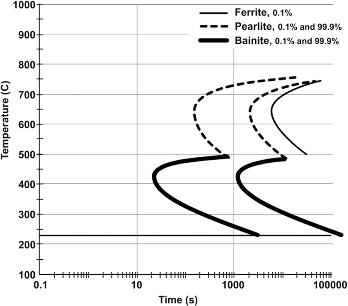
3.1. Kinetics of Isothermal TransformationThe TTT diagrams of C–Mn–Si and C–Mn–Si–Mo alloys are calculated using JMatPro® and given in Figs. 1 and 2, respectively. Ferrite 0.1%, Pearlite 0.1%, and Bainite 0.1% represent that the transformation is started whereas Bainite 99.9% and Pearlite 99.9% represent that the transformation is completed. There are two C curves for both pearlite and bainite transformations. These curves are the transformation start and finish curves for the selected temperatures. The Ms temperatures for C–Mn–Si and for C–Mn–Si–Mo alloys are presented as 254°C and 233°C, respectively. In view of these data, the isothermal transformation temperatures are selected as 250°C and 300°C for C–Mn–Si alloy, whereas they are 230°C and 280°C for C–Mn–Si–Mo alloy.

Calculated TTT diagrams for C–Mn–Si alloy.
Calculated TTT diagrams for C–Mn–Si–Mo alloy.
Upon an isothermal transformation at low temperatures, the bainitic ferrite grows into austenite. After the growth, the supersaturated carbon in ferrite is partitioned with austenite due to a displacive mechanism.33,34) At this stage, carbide precipitation takes place both in ferrite and between austenite/ferrite boundaries. However, it has been shown that in steels containing high Si, the carbide precipitation in bainitic ferrite is retarded.35) As a result, more carbon is partitioned between ferrite and austenite causing supersaturation of austenite. The austenite with excess carbon cannot transform to martensite upon cooling and retain as thin austenite films between ferrite layers. If the transformation is incomplete, some blocky austenite regions may be seen in the microstructure which are named as blocky M/A (austenite/martensite) due to the fact that they may either retain as austenite islands or transform to martensite.
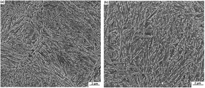
3.2. Microstructural ExaminationThe calculated TTT diagram indicates that for C–Mn–Si alloy, isothermal treatment for 4 h is necessary to obtain 100% bainite at 250°C. The microstructure of the C–Mn–Si sample transformed at 250°C (very close to the Ms) for 15 min and 1 h are shown in Figs. 3(a) and 3(b), respectively. A short transformation time carried out at 250°C (15 min) causes the formation of bainitic ferrite needles in the matrix (Fig. 3(a)). However, as seen in Fig. 3(a), the flat regions between the bainite needles indicate that nearly 50% of the austenite does not transform into bainite. These, flat austenite regions probably transform to martensite when the specimen is cooled down to room temperature after about a 15 min of bainitic transformation. When the transformation time is increased to 1 h, it is clear that most of the austenite transforms into bainite as seen in Fig. 3(b). A few untransformed regions in the bainitic structure are shown with arrows and named as blocky M/A (martensite/austenite) islands (Fig. 3(b)). When the transformation time is extended, the amount of blocky austenite further decreases after isothermal treatment for 3 h and completely disappears after 12 h. In the C–Mn–Si specimen, at the end of isothermal treatment for 12 h, the microstructure consists of only acicular lower bainite (Fig. 4). The microstructural observations indicate that there is a small shift in the bainitic transformation time of calculated diagrams and metallographic observations.

(a) SEM micrograph of C–Mn–Si alloy isothermal treated at 250°C for 15 min. (b) SEM micrograph of C–Mn–Si alloy isothermal treated at 250°C for 1 h.
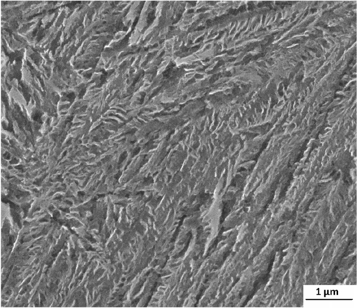
SEM micrograph of C–Mn–Si alloy isothermal treated at 250°C for 12 h.
When the transformation temperature is increased to 300°C, a transformation time of 50 min is sufficient to obtain nearly 100% bainitic structure in C–Mn–Si alloy according to the calculated diagrams. The blocky austenite regions can be seen in specimens transformed at 300°C for 15 min (Fig. 5(a)). However, the blocky austenite regions could still be detected even after the treatment of 3 h in the salt bath (Fig. 5(c)). The blocky austenite regions in specimens transformed at 300°C for 15 min and 3 h can be seen more clearly at higher magnifications as shown in Figs. 5(b) and 5(d), respectively. Either at 300°C or 250°C, carbide precipitation within bainite sheaves is not observed under high-resolution SEM. It seems that 1.2wt%Si could inhibit the precipitation of coarse cementite in lower bainite.
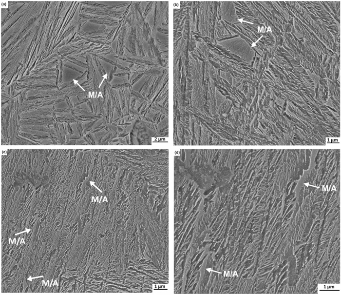
(a) (b) SEM micrographs of C–Mn–Si alloy isothermal treated at 300°C for 15 min. (c) (d) SEM micrograph of C–Mn–Si alloy after isothermal treatment at 300°C for 3 h. The blocky M/A regions can be seen at several locations.
As far as the C–Mn–Si–Mo alloy is concerned, the completion of bainitic transformation is shifted to longer times due to the presence of Mo. When the transformation treatment is carried out at a temperature very close to the Ms temperature, i.e. 230°C for 12 h, the microstructure reveals that there is a substantial amount of bainite formation (Fig. 6(a)). An increase in time up to 48 h causes almost 100% of bainitic transformation, though there are just a few flat regions which may be small blocky M/A (Fig. 6(b)).

(a) SEM micrograph of C–Mn–Si–Mo alloy isothermal treated at 230°C for 12 h. (b) SEM micrograph of C–Mn–Si–Mo alloy isothermal treated at 230°C for 48 h.
After an isothermal transformation at 280°C for 12 h, a change in the morphology of bainite is observed in the C–Mn–Si–Mo alloy. It appears that bainitic ferrite become coarser and flatter (Fig. 7). Furthermore, it is evident that there is a very thin, carbide-like precipitation located inside and within the sheaves (light contrasted precipitates in Fig. 7).

SEM micrograph of C–Mn–Si–Mo alloy isothermally treated at 280°C for 12 h. Very thin, elongated carbide precipitation within and between the sheaves can be seen (white precipitates).
In order to find the carbide contents of the bainitic structures of both C–Mn–Si and C–Mn–Si–Mo specimens approximately, the carbide extraction method is used.27) For this purpose, the 100% bainitic specimens transformed at a temperature very close to their Ms temperatures were selected. It is found that the carbide contents of C–Mn–Si and C–Mn–Si–Mo specimens are 0.08 wt% and 1.8 wt%, respectively. It seems that the 1.2wt%Si retarded the carbide precipitation in the bainitic C–Mn–Si specimen but seems to be not very effective in Mo-containing specimen.
3.2.1. HardnessesThe hardness values of all samples are introduced in Fig. 8. For comparison purposes, the hardness values of quenched specimens that have fully martensitic structure are also presented.
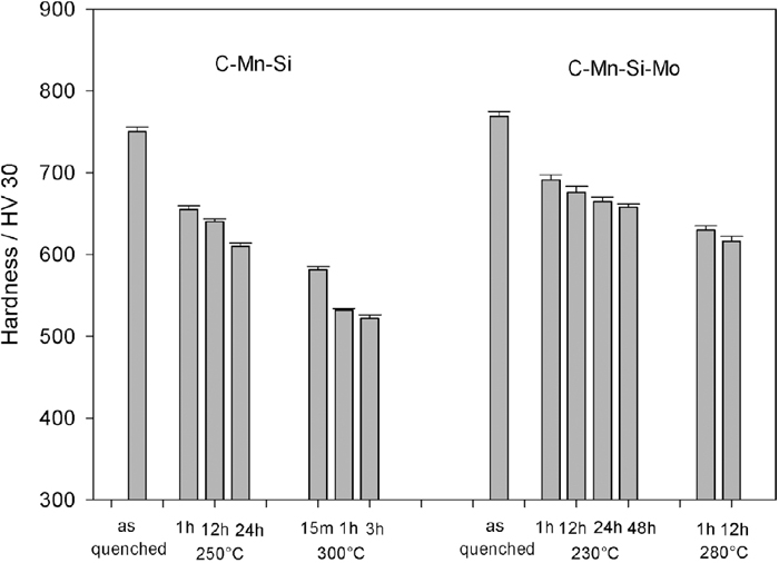
Hardness values of the isothermal treated C–Mn–Si and C–Mn–Si–Mo alloys.
The hardness values of as-quenched martensitic specimens of C–Mn–Si and C–Mn–Si–Mo exhibit 750 HV and 770 HV, respectively. The lower bainitic structures of these alloys (transformed at a temperature very close to their Ms) are in the range of 640 HV–660 HV depending on the transformation time. Moreover, an increase in the transformation temperature causes a decrease in the hardness values.
3.3. Retained Austenite (RA) MeasurementsThe retained austenite contents of all samples found by XRD are shown in Fig. 9. Oil-quenched specimens do not contain any RA. On the other hand, the bainitic structures of C–Mn–Si steel give rise to RA peaks. An increase in the amount of bainitic ferrite in the structure causes an increase in the amount of RA as well (e.g. an increase in transformation time from 1 h to 12 h at 250°C causes an increase in the amount of RA from 6% to 10%, respectively). Another finding is that the amount of retained austenite is higher in the specimen transformed at 300°C (14%) with respect to the specimen transformed at 250°C (10%).
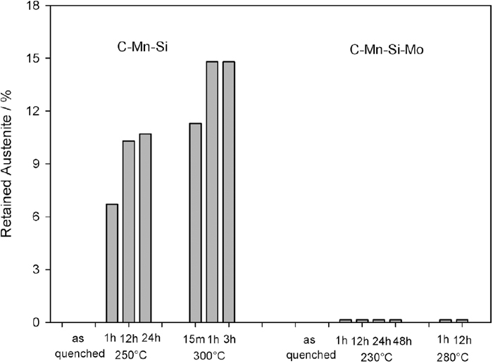
The retained austenite contents of all the specimens.
In contrast to C–Mn–Si steels, in the bainitic C–Mn–Si–Mo steels, retained austenite cannot be detected.
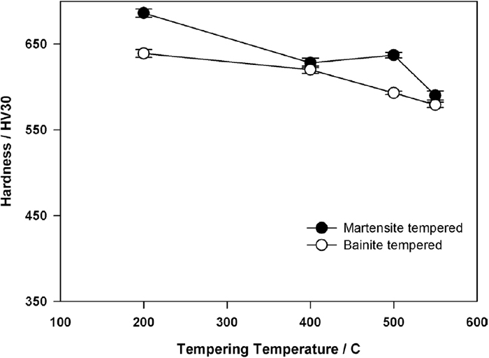
3.4. Tempering StudiesIn Fig. 10, the variations in the hardness of bainitic and martensitic C–Mn–Si alloy specimens are seen with respect to the tempering temperatures. The martensitic sample exhibits the expected behavior: An increase in the tempering temperature from 200°C to 550°C causes a decrease in the hardness. Both bainitic and martensitic steels possess similar hardness values in the range of 400°C–550°C.

The variation in hardness of martensite and bainite in C–Mn–Si alloy upon tempering.
In C–Mn–Si–Mo specimens, the martensitic sample exhibits a small peak hardness at 500°C (Fig. 11). On the other hand, bainitic specimens do not show a secondary hardening peak. However, when the tempering behaviors of bainitic samples of C–Mn–Si and C–Mn–Si–Mo alloys are compared, it is observed that there is such a retardation of softening in C–Mn–Si–Mo alloy that the differences in tempered hardness values become more evident in the range 500°C–550°C (Fig. 12).
The variation in hardness of martensite and bainite in C–Mn–Si–Mo alloy upon tempering.

The comparison of hardness values of bainite in tempered C–Mn–Si and C–Mn–Si–Mo alloys.
The microstructures of the bainitic specimens after tempering at 500°C are given in Fig. 13. It should be pointed out that, there is some amount of carbide precipitation in the form of small spherical particles in both C–Mn–Si and C–Mn–Si–Mo specimens.
(a) SEM micrograph of the bainitic specimens after tempering at 500°C for bainitic C–Mn–Si alloy. (b) SEM micrograph of the bainitic specimens after tempering at 500°C for bainitic C–Mn–Si–Mo alloy.
As shown in Fig. 9, the bainitic specimens of C–Mn–Si alloy contain different amounts of retained austenite due to the isothermal transformation treatment but it could not be detected in C–Mn–Si–Mo alloy. The change in retained austenite contents of C–Mn–Si specimens can be explained with the bainite growth mechanism in Si-containing steels and T0’ phenomena. In the isothermal transformation, the bainitic ferrite grows into austenite and the supersaturated carbon in ferrite is partitioned with austenite due to a displacive mechanism.33,34) It is known that in steels containing high Si, the carbide precipitation in bainitic ferrite is retarded.10,11,12,13,14,35,36) As a result, more carbon is partitioned between ferrite and austenite causing supersaturation of austenite. Upon cooling to room temperature, the carbon enriched austenite retains in the microstructure either in the form of thin films between the bainite sheaves or in the form of bulk islands (named as M/A).
Several thermodynamic conditions must be met for carbide-free bainite formation to take place.31,36,37) These conditions are as follows: 1. Carbon concentration in austenite must be less than T0’, 2. The carbon content in austenite must be above the para-equilibrium curve of austenite-cementite (A/Ap+Fe3C) so that no cementite precipitation takes place and 3. No martensite must form at that temperature, i.e. temperature must lie above Ms. The T0’ and para–equilibrium curves for both C–Mn–Si and C–Mn–Si–Mo alloys are plotted in Fig. 14 using Thermo-Calc software. For C–Mn–Si alloy, the feasible region for carbide-free bainitic transformation is bounded by T0’, Para-equilibrium, and Ms curves. In the case of C–Mn–Si alloy, the higher amount of retained austenite in specimens transformed at elevated temperatures (300°C vs. 250°C) can be related to T0’ phenomena. As seen in Fig. 14, at higher temperatures, the bainite reaction stops at an earlier stage because beyond the T0’ line bainite reaction cannot proceed.
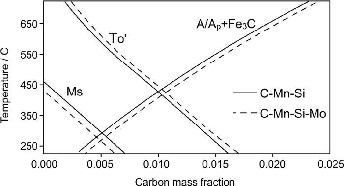
The schematic drawing of T0’ curve. At the right of this curve, the bainitic reaction cannot proceed.
The effects of Mo on T0’ and para-equilibrium curves are also calculated and shown with dashed lines in Fig. 14. It is detected that for Mo-containing alloy, both T0’ and para-equilibrium curves shift to higher carbon percentages, hence the carbide-free bainite area is enlarged. This implies that bainite transformation can go into completion much more easily than transformation of Mo free alloy. However, the plots of Thermo-Calc cannot explain the absence of retained austenite in Mo-containing alloy, as the carbide-free bainite region is larger than that of C–Mn–Si alloy, there should be no carbide precipitation and consequently the supersaturated austenite should remain in the microstructure. The effect of Mo in a quenched and partitioned low carbon and high Si steels has been studied by E. De Moor et al.24) and G.A. Thomas et al.25) and it has been found that the Mo-containing alloy exhibits greater austenite fractions than the base alloy and the stability of retained austenite is increased. Molybdenum is a ferrite stabilizer and this alloy contains 2wt% Mo. This amount may avoid the formation of supersaturated austenite. Also, Mo may cause carbide formation which avoids the retention of the austenite.
The contradictory results on the effect of retained austenite can possibly be related to the carbide precipitation kinetics and mechanisms in the different alloy systems. In this study, the increase in volume fraction of retained austenite due to an increase in the transformation time (from 12 h to 24 h) at 250°C can be explained with the same mechanism: A longer transformation time causes formation of more bainite and hence high amount of carbon rejection into austenite. This results in a highly supersaturated austenite in terms of carbon. However, the bainitic transformation at 300°C exhibits a higher amount of retained austenite than that of samples transformed at 250°C. A very similar result has been reported by Caballero et al.38) who studied the bainitic transformation of 1.0wt%C-1.6wt%Si-1.9wt%Mn-1.3wt%Cr steel at high temperatures and indicated that the retention of the high amount of austenite at around 300°C occurs due to T0’ phenomena. It is known that both Mn and Cr shift the T0’ curve to lower carbon content and thus, the bainitic transformation stops at an earlier stage as the T0’ curve will be reached more quickly. In our study, the Mn and Cr contents of the alloys are minimized for shifting the T0’ curve, but the formation of blocky M/A regions at the high transformation temperatures cannot be avoided. The diffusivities of Cr and Mo atoms are very low at the bainitic transformation temperatures, therefore precipitations of M6C and M2C alloy carbides are not expected. The carbide precipitation from supersaturated ferrite follows similar stages as in the case of the tempered martensite. First, ε-carbide is seen and then it is replaced with Fe3C at higher temperatures.12,39) Also, there is an experimental evidence that the precipitation of the transition ε-carbide is enhanced in the presence of silicon40,41,42) and even an attempt was made by D.V. Edmonds et al.43) to draw two different C-curves for the precipitation of transition ε-carbide and cementite.
In this study, the carbide extraction studies show that there is a carbide precipitation in Mo-containing alloy during bainitic transformation which most probably inhibits austenite retention. The carbide precipitation within bainite is demonstrated by carbide extraction tests and a fully bainitic specimen exhibits around 1.8 wt% carbide in its microstructure. Also, in Fig. 7, very fine carbide precipitation can be seen in the form of parallel thin carbide films in specimen C–Mn–Si–Mo alloy after transformation at 280°C but carbide precipitation is not observed in C–Mn–Si alloy.
The residue of the carbide extraction, though several peaks fit ε -carbide, cannot be indexed 100% in XRD due to excessive FeCl2 contamination and overlapping of the peaks. A detailed analysis is carried out to characterize the carbides in bainitic microstructures of C–Mn–Si–Mo alloy after different heat treatment experiments. However, all these results indicate that the effect of Si on the retardation of carbide precipitation is complex and needs further study in different alloy systems including the high carbon content and Mo systems.
4.2. The Tempering Response of SpecimensIt is a well-known fact that the response of bainite to tempering is slow because the long transformation stages of bainite also act as auto tempering.12,21,44,45,46) Similar behavior is observed in this study as well. The hardness of martensite decreases more rapidly with respect to that of bainite upon tempering at either 200°C or 400°C. As seen in Figs. 10 and 11, this observation is valid for both C–Si–Mn steel and C–Si–Mn–Mo steel. On the other hand, upon tempering at 500°C and 550°C, bainite and martensite exhibit very similar hardness values in C–Si–Mn steel. In a recent study carried out by Kang et al.,21) it has been found out that the microstructural coarsening becomes detectable together with precipitation of carbides upon tempering above 360°C which results in a sudden decrease in the hardness values. On the other hand, Garcia-Mateo et al.45) have shown that in a 1.0wt%C steel, the softening of bainite is not seen if tempering is carried out below 550°C. This effect is related to the carbides precipitated in bainite which leads to some precipitation strengthening during the early stages of tempering. The hardness results obtained in this study for tempered C–Mn–Si alloys are closer to the results of Kang et al.,21) probably due to the similarity in the carbon content of the steels studied. There are a few studies on the effect of Mo on the tempering of bainite. The retardation to softening in Mo-containing steels is also shown by Baker and Nutting39) and Irvine and Pickering47) with a study based on low carbon steels. However, in this study, the carbon content of C–Mn–Si–Mo steel is high i.e. 0.6wt%, therefore, a secondary hardening peak is expected rather than retardation of softening in the bainitic specimens. It is possible that the amount of Mo (2wt%) is not enough to obtain a well-defined peak. In studies of high strength bainitic steels, the Mo content is kept low, i.e. in the range 0.2%–0.4% to avoid temper embrittlement. However, Mo as an alloying element has several important effects on steels. It promotes bainite formation.20,21,22,23) Mo exhibits a secondary hardening peak at around 500°C when a sufficient amount is added as an alloying element. The formation of secondary hardening peak in Mo-containing steels is related to the replacement of coarse cementite particles with much finer alloy carbides.20,48) In this study, the secondary hardening potential of bainitic steel is lower than its martensitic counterpart most probably due to the early carbide precipitation during the bainitic transformation (which is named as auto tempering) and loss of some carbon for secondary hardening peak. In Mo free steel, a secondary hardening peak is not observed both in martensitic and bainitic specimens. Rather the hardness is decreased gradually with an increase in the tempering temperature.
In parallel to the above discussion, in this study, the fine and spherical carbides observed in the microstructure of tempered specimens of both C–Mn–Si and C–Mn–Si–Mo (Fig. 13) are most probably coarse cementite particles.
(1) In both C–Mn–Si and C–Mn–Si–Mo alloys, the bainitic transformation is completed after an isothermal treatment at a temperature very close to their Ms temperatures, i.e. 250°C and 230°C, respectively. However, the Bainite 99.9% curves seem to be shifted to the longer time values than that of the calculated TTT diagrams.
(2) In C–Mn–Si steel, the amount of retained austenite increases with increasing transformation time. When the bainitic transformation at 250°C is completed, the specimen contains nearly 10% retained austenite. Moreover, the bainitic structure in this steel is nearly free of carbide.
(3) In C–Mn–Si–Mo alloy, the retained austenite phase could not be detected after 100% bainitic transformation either at 230°C for 48 h or at 280°C for 12 h. Rather, carbide precipitation is evident in the bainitic microstructure.
(4) An increase in isothermal transformation temperature from 250°C to 300°C slows down the transformation rate and leads to retention of blocky M/A regions in the microstructure of C–Mn–Si alloy in agreement with T0 phenomena. The absence of retained austenite in Mo-containing steel indicates that these blocky regions consist of martensite.
(5) The tempering behavior of C–Mn–Si–Mo alloy is considerably different in comparison with that of the Mo free alloy in the 200°C–550°C tempering range. In Mo-containing steel, the martensitic specimen shows a secondary hardening peak upon tempering at 500°C. The bainitic specimens do not show a peak hardness but the softening is retarded upon tempering in the same temperature range.
The authors are grateful to Asil Çelik San.ve Tic. A.Ş./Bursa-Turkey for supplying the 60SiMn5 steel and to Çemtaş Çelik Makina Sanayi ve Ticaret A.Ş./Bursa-Turkey for supplying the calculated TTT graphs of JMatPro®.