Abstract
A continuous solidification process of blast furnace slag was developed to promote the use of air-cooled slag coarse aggregate for concrete. In this process, the molten slag can solidify in only 120 s and the slag thickness is about 25 mm. This process suppresses gas generation and greatly reduces water absorption. Most of the slag is crystalline, and part of the slag has a glass layer on its surface. Slag with a glass layer is brittle because it contains several cracks. Therefore, microscopic observation and thermal stress analysis of the solidified slag were carried out to clarify the mechanism of crack generation in the plate-like slag. In the microscopic observation, several cracks with a length of about 8 mm were found in the slag with the glass layer. From the analysis, in the cooling pattern of the slag on the piled slag a temperature difference of about 200 K exists between the center and the mold side in the slag pit, and keeping this difference results in tensile stress of more than 50 MPa. However, in the cooling pattern of the crystalline slag in the piled slag, the temperature gradient in the slag in the slag pit was very small because the slag was retained in the piled slag, and as a result, the thermal stress was almost 0 MPa.
1. Introduction
In previous research,1,2,3,4,5,6) we demonstrated that plate-shaped solidified slags with few pores and low water absorption suitable for use as coarse aggregate for concrete can be obtained in a continuous process by pouring molten blast furnace slag into steel molds to a thickness of approximately 25 mm. These desirable properties can be achieved because pore formation and growth are suppressed by rapidly solidifying molten slag. However, the solidified slag surface in contact with the mold may be glassy or the slag may be completely crystalline, depending on the cooling conditions. Although the amount of slag with a remaining glass layer is small, this type of solidified slag is brittle and cracks easily on impact. On the other hand, the completely crystalline slag has high shatter strength.
Internal cracks can be observed in the solidified slag plates with the glassy contact surface. It is considered that these slags break easily when impact is applied due to the existence of the cracks. When producing coarse aggregate for concrete from air-cooled slag, the particle size is adjusted by crushing and classification to a size of 20 to 5 mm. Regarding the particle shape after crushing, particles with a rounded shape, i.e., without sharp angles, and a heterogenous size and shape, are suitable for use in concrete.7) However, when the above-mentioned solidified slag plates with internal cracks are crushed, the coarse aggregate is nearly a cube or rectangular shape, and the coarse aggregate also displays size segregation. Due to these inferior characteristics, the actual use ratio is small, and use of the slag tends to reduce concrete properties. Thus, preventing crack formation is essential for producing air-cooled slag coarse aggregate which is suitable for concrete.
In the field of plate glass, various reports have examined the mechanism of crack generation and the changes in strength associated with the thermal history of the glass. Narayanaswamy et al. examined the stress generated in the glass tempering process and reported that the density gradient in the glass plate thickness direction is the controlling factor for stress generation during tempering.8) Yuse and Sano examined the behavior of crack growth when plate glass is cooled and reported that the types of cracks generated in the glass differed depending on the temperature differential in the glass plate thickness direction and the immersion speed in water.9) Sakka et al. reported that the strength of glass changes by as much as three times depending on the heat treatment conditions, even with the same glass composition.10) However, the mechanism of crack generation and strength under complex conditions such as heating and air-cooling after unidirectional quenching, as in the process described here, remained to be clarified.
In this research, we studied the behavior of crack generation in the cooling process of solidified slag plates produced using the continuous solidification process for blast furnace slag described in our previous report.1,2) The high-temperature physical properties of the slag, including tensile strength, compressive strength, Young’s modulus, the modulus of rigidity and Poisson’s ratio, which are necessary for a thermal stress analysis, were measured, and a thermal stress analysis was conducted using that information and the temperature data from the heat transfer analysis in the previous report. As a result, the conditions for crack generation in solidified slags with a remaining glassy surface and completely crystalline solidified slags were clarified, and a mechanism of crack generation based on the thermal stress in the cooling process was studied.
2. Experimental Method
2.1. Solidified Slag Production Method
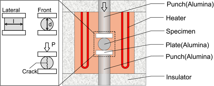
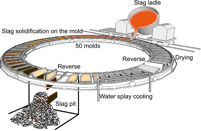
Solidified slag plates were produced by the same method as in our previous report.1,2) Figure 1 shows a schematic diagram of the equipment. The equipment comprises 50 molds arranged in a circle on a carriage, a runner for pouring the molten slag into the molds, a slag pit where the solidified slags are piled and air-cooled, and a spray nozzle unit which is used to cool the molds. Molten slag is poured from the blast furnace slag ladle at a flow rate of approximately 2.0 t/min so as to obtain a solidified thickness of 20 to 30 mm on the molds. The solidified slag is cooled for 120 s on the moving molds, solidifying in a plate-like form, and the solidified slag plates are then dropped into the slag pit by inverting the molds. Following this, about 30 t of slag is collected in the slag pit, where it is air-cooled. In this study, solidified slag samples were collected from outer surface and the interior of the slag pile after cooling to room temperature. The solidified slags were mostly slags with a completely crystalline structure (hereinafter, referred to as “crystal slag”), together with some slags with a glassy surface layer on the side which was in contact with the mold (“slag with a glass layer”).
The condition of crack generation in the cut cross section of the recovered solidified slag samples was observed.
2.2. Measurement Method of Impact Strength of Solidified Slags
To evaluate the strength of the solidified slags, a shatter test was conducted based on JIS M 8711, Iron ore sinter – Determination of shatter strength. The specimens for the measurements were prepared by coarsely crushing the slag with a glass layer and crystal slag samples to 40 to 100 mm in size. The weight of the test specimens was 3 kg.
The weight of the specimen before the test was defined as B [kg]. The remaining amount on the 40 mm screen after the test were expressed as A40 [kg]. Also, The remaining amount on the 20 mm screen was A20 [kg]. As the shatter strength of the solidified slag, the remaining ratios of over 40 mm and over 20 mm in sizes after the shatter test were defined as S40 [%] and S20 [%], respectively, as expressed by the following equations.
|
S
40
[ % ]=
A
40
/B×100
| (1) |
|
S
20
[ % ]=
A
20
/B×100
| (2) |
In addition, a shatter test was also conducted to evaluate the strength of the coarse aggregate after classification following crushing with the impact crusher.
2.3. Measurement Method of High Temperature Tensile Strength and Compressive Strength
In order to evaluate the crack generation behavior in solidified slag plates in the continuous solidification process of blast furnace slag, the tensile strength and compressive strength of the slag were measured in the temperature range between the slag solidification temperature and room temperature.
The tensile strength of the blast furnace slag was measured using cylindrical specimens in accordance with JIS A 1113, Method of test for splitting tensile strength of concrete. Figure 2 shows a schematic diagram of the apparatus used in the high temperature compression test. The specimens for this test were prepared by heating and melting granulated blast furnace slag to 1773 K with a high frequency induction melting furnace, followed by slow cooling at 100 K/h, and then cutting the slag to a cylindrical shape with a diameter of 10 mm and a length of 15 mm. The cylindrical specimen was held in the testing machine in a horizontal position, as shown in Fig. 2. The specimen was then heated to the measurement temperature at 250 K/h and held for 30 min, after which lowering of the upper punch was started. The lowering speed was set at 0.5 mm/min, and the load was measured at intervals of 0.05 s. Tensile strength σ [N/mm2] was calculated by using Eq. (3).11)
where,
P is maximum load [N],
d is diameter of test specimen [mm] and
l is length of test specimen [mm]. Measurements were performed room temperature and at steps of 250 K from 523 K to 1273 K and at steps of 50 K from 1273 K to 1323 K.
The specimen for use in measurement of the compressive strength of the blast furnace slag was cut out from a 25 mm thick solidified slag plate to a square columnar shape with horizontal dimensions of 10 mm × 10 mm × height of 15 mm so that the height direction coincided with the thickness direction of the slag plate. The device shown in Fig. 2 was used in the measurement. The samples were heated to the target temperature at 250 K/h and held for 10 min at that temperature, after which the upper punch was lowered. The lowering speed was the same as in the tensile test. Measurements were performed at room temperature and steps of 50 K from 1273 K to 1423 K.
2.4. Measurement Method of High Temperature Physical Properties
The high temperature physical properties of the blast furnace slag are necessary for a thermal stress analysis. Because there was no past research in this connection, Young’s modulus (E [Pa]), the modulus of rigidity (G [Pa]) and Poisson’s ratio (v [–]) were determined by the bending resonance method using an elastic modulus measurement apparatus based on JIS R 1602, Testing methods for elastic modulus of fine ceramics and JIS R 1605, Testing methods for elastic modulus of fine ceramics at elevated temperature. The test specimens were prepared by the same method as described above; that is, granulated slag was melted with an induction furnace, followed by slow cooling, after which the solidified slag was cut to the prescribed shape. The dimensions of the specimens were a width of 20 mm × length of 100 mm × thickness of 2 mm. Measurements were performed at room temperature and at steps of 100 K from 373 K to 1373 K. The specimens were heated up at 10 K/min and then measured after holding for 10 min at the target temperature. After the measurements, Young’s modulus (E), the modulus of rigidity (G) and Poisson’s ratio (v) were calculated by using Eqs. (4), (5), (6).12,13)
|
E=0.9465⋅
M⋅
f
y
2
w
h
⋅
(
L
w
l
)
3
⋅{
1+6.59
(
w
l
L
)
2
}
| (4) |
|
G=
4LM
f
g
2
w
h
w
l
⋅
w
r
+(1/
w
r
)
4
w
r
-2.52
w
r
2
+0.21
w
r
6
⋅
1
(1+A)
| (5) |
where,
fy is resonance frequency of primary bending mode [Hz],
fg is resonance frequency of primary return mode [Hz],
wh is width of specimen [m],
wl is thickness of specimen [m],
L is length of specimen [m],
wr is ratio of
wl and
wh [–],
M is mass of specimen [kg] and
A is shape correction factor [–] (according to ASTM-C848,
A=1.78%).
Measurement of the thermal expansion coefficient α (K−1) was performed by the total expansion thermomechanical analysis method using a DIL402C (Netzsch) based on the thermal expansion measurement method provided in JIS R 1618, Measuring method of thermal expansion of fine ceramics by thermomechanical analysis. The specimen was heated up at 10 K/min under a nitrogen gas atmosphere, and measurements were performed at steps of 100 K from 573 K to 1373 K. The dimensions of the specimens were a depth of 5 mm × width of 5 mm × length of 10 mm.
The coefficient of thermal expansion (α) from the standard temperature (303 K) to the measurement temperature (X [K]) is obtained from Eq. (7).
where,
Lr is length of specimen at standard temperature, and Δ
L is amount of expansion of specimen from 303 K to X [K].
3. Experimental Results
3.1. Crack Generation of Solidified Slag Plates
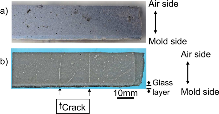
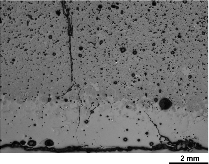
Figure 3 shows the cross-sectional photos of the plate-shaped solidified slags. Figure 3(a) shows the crystal slag and b) shows the slag with a glass layer. Both slags contain few pores, and whereas the absolute density of conventional air-cooled slag is 2.36 to 2.52 g/cm3,1) both of the slags produced by this process were dense, having the absolute density of 2.82 g/cm3 independent of the presence or absence of the glass layer. No cracks were observed in the crystal slag, cracks had occurred in the slag with a glass layer. An enlarged image of the slag with a glass layer is shown in Fig. 4. Multiple cracks had occurred in the glass layer and propagated in the thickness direction. The shortest of these cracks was 2 mm, and the longest had penetrated completely through the glass layer to the crystalline.
3.2. Impact Strength of Solidified Slag
Table 1 shows the results of a comparison of the shatter strength S40 and S20 of the slag with a glass layer and the crystal slag. From the values of shatter strength S40, more than 80% of the crystal slag maintained an original size of 40 mm or larger, whereas more than 80% of the slag with a glass layer had fragmented into smaller pieces. It can be understood that the slag with a glass layer shatters easily in comparison with the crystal slag. However, in the case of shatter strength S20, more than 80% of the slag with a glass layer was also 20 mm or larger. In other words, although the slag with a glass layer shatters along cracks, this does not mean that fine pieces increase.
Table 1. Shutter strength.
| S40 [%] | S20 [%] |
|---|
| Slag with glass layer | 14.6 | 86.1 |
| Crystalline slag | 83.9 | 98.6 |
Figure 5 shows the particle size distributions before and after the shatter test of the coarse aggregate. Since there was no difference in the particle size distributions before and after the test, it can be thought that the cracks that exist in the solidified slag can be sufficiently removed by crushing with an impact-type crushing machine, even though cracks occur in the slag.
3.3. High Temperature Tensile Strength and Compressive Strength of Blast Furnace Slag
The high temperature tensile strength of the blast furnace slag is shown in Fig. 6. The room temperature tensile strength of blast furnace slag is 8.5 MPa to 10.1 MPa, which was similar to the tensile strength of 5 MPa to 10 MPa displayed by natural stone (granite, limestone, andesite).14) Up to 1323 K, the blast furnace slag maintained approximately the same strength as at room temperature, but its tensile strength decreased remarkably with the increase of temperature when it exceeded 1323 K.
The high temperature compressive strength of the blast furnace slag is shown in Fig. 7. Compressive strength was 200 MPa or more at room temperature, and was still high (193.7 MPa) at 1323 K. At higher temperatures, compressive strength also decreased as the temperature increased. From these results, it can be concluded that blast furnace slag, like natural stone and unreinforced concrete, is characterized by high compressive strength but relatively low tensile strength.
3.4. High Temperature Physical Properties of Blast Furnace Slag
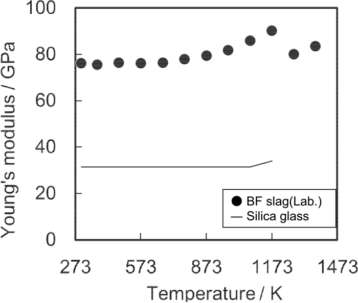
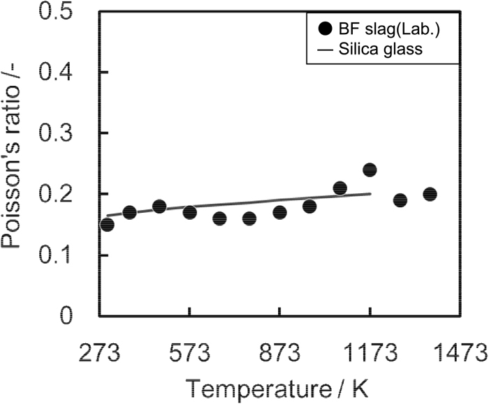
Figures 8 and 9 show the measurement results for Young’s modulus and Poisson’s ratio, respectively, together with the physical property values of quartz glass.15) Young’s modulus and Poisson’s ratio were almost constant from room temperature to 1373 K. Compared with quartz glass, Young’s modulus of blast furnace slag is 2.5 times higher and Poisson’s ratio is on approximately the same level as quartz glass.
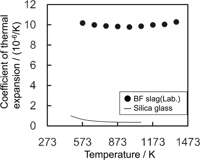
The measurement results for the coefficient of thermal expansion are shown in Fig. 10, together with the value of quartz glass. The coefficient of thermal expansion of the blast furnace slag was substantially constant against temperature.
4. Discussion
4.1. Thermal Stress Analysis Model
The behavior of crack generation in the cooling process was studied by a thermal stress analysis. The basic equation of thermal stress is shown in Eq. (8).16) Here, σ is thermal stress, α is coefficient of linear expansion, v is Poisson’s ratio and E is Young’s modulus. In the slag cooling process, thermal stress is generated by the temperature differences that occur in the interior of the solidified slags. It is possible to calculate thermal stress by measuring the physical property values shown above and carrying out a FEM analysis using those results in combination with the results of the heat transfer analysis in the previous report.3) The reason why cracks do not occur in the crystal slag and the timing of crack generation in the slag with a glass layer can be clarified from the calculated values of thermal stress and the high temperature tensile strength and compressive strength measurements of the blast furnace slag.
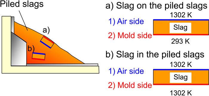
The calculation model used in the analysis of the continuous solidification process of the slag is the same as in the previous report3) and is shown in Fig. 11. For the specific heat capacity and thermal conductivity, which are necessary in the heat transfer analysis, the measured values reported by the authors3) were used in the range up to 1373 K, and the measured value of the heat capacity of blast furnace slag reported by Ogino and Nishikawa17) and the measured values of heat transfer reported by Kang and Morita18) were used for the range from 1473 to 1773 K. For density, the measured values in the previous report1,2) were used with a linear approximation up to 1773 K. Two calculation conditions were examined, a) slag surface on the piled slags and b) slag inside the piled slag in the slag pit. Condition a) was defined as the condition in which the surface of the solidified slag that had been in contact with the mold surface is at the outer surface of the piled slags. The solidified thickness of the slag was assumed to be 25 mm. The temperature of the slags piled in the slag pit was defined as the adiabatic condition at 120 s after the solidified slag was dropped from the molds and was set at 1302 K, which is the value when the cross-sectional temperature distribution of the solidified slags became uniform. The value of thermal resistance was set at 0.0009 (m2/K)/W.
In order to confirm the density difference between the glassy and crystalline blast furnace slag, the densities of granulated slag (water-cooled blast furnace slag), which is completely glassy, and air-cooled slag, which is crystalline, were measured and compared. Density was measured by the pycnometry in JIS Z 8807, Methods of measuring density and specific gravity of solid. The true density of the granulated slag was 2.91 g/cm3, which was almost identical with that of blast furnace slag fine powder in past reports, which gave values of 2.9119,20) to 2.9221) g/cm3. The measured value of the air-cooled slag was 2.94 g/cm3. Since the density difference between the glassy granulated slag and the crystalline air-cooled slag at room temperature was small, it is thought that the effect of volume change due to the phase transformation is negligible.
In Fig. 3(a), the surface where the slag had been in contact with the mold was vitrified and was then crystallized when the slag was held in the slag pit,1) but cracks did not occur in the part where the glass was crystallized. On the other hand, in Fig. 3(b), cracks were not limited to the glassy part, but occurred across the glassy part, in some cases extending into the crystalline part, and the glassy part did not delaminate.
Considering the facts mentioned above, it can be thought that the effect of the density difference between the glassy part and the crystalline part of the slag was small. Therefore, in this analysis, all of the slag was calculated as in a solid condition and crystalline.
4.2. Thermal Stress Analysis
4.2.1. Slag on Surface of Piled Slags
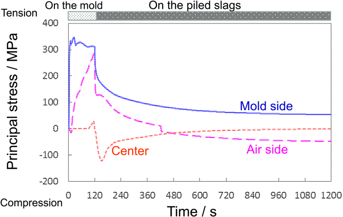
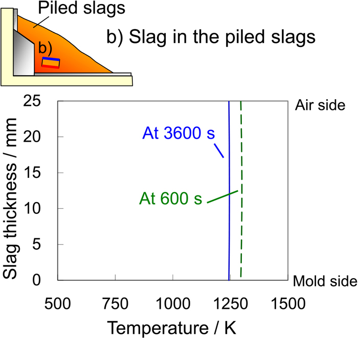
Figure 12 shows the time-dependent change of the temperature on the mold side, at the center and on the air side of the slag cooled at the surface of the piled slags. Charging of slag into the mold is set at 0 s. The slag is discharged into the pit at 120 s and is positioned on the exposed surface of the pile. It was found that this slag is cooled while maintaining a temperature difference of approximately 200 K between the mold side and the slag center and between the slag center and the air side even at 1200 s. Since the temperature on the mold side of the slag doesn’t rise to the crystallization temperature of 1173 K,22) the slag of the mold side remains as glass. The results of a calculation of the principal thermal stress generated under this condition are shown in Fig. 13, where positive values indicate tensile stress and negative values indicate compressive stress. Tensile stress acts on the mold side. On the air side, tensile stress changed to compressive stress at 424 s. Almost no stress occurs in the central part of the slag. Figures 14 and 15 shows the temperature and the thermal principal stress distribution in the slag thickness direction at 600 s and 3600 s. It was found that compressive stress of 30 MPa at 1175 K exists on the air side, while tensile stress of 70 MPa at 802 K exists on the mold side, even after as much as 3600 s, because the temperature in the slag thickness direction does not become uniform. Based on this, it can be estimated that cracks occurred from the mold side because the tensile stress acting on the mold side exceeded 8 MPa, that is, the tensile strength of the slag.
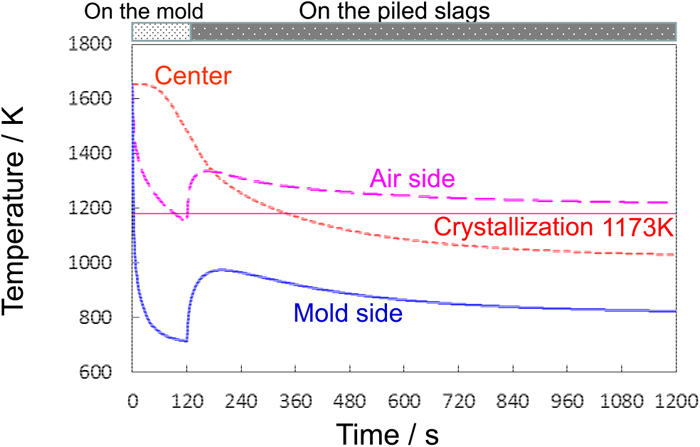
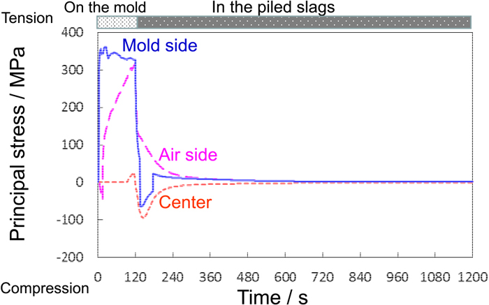
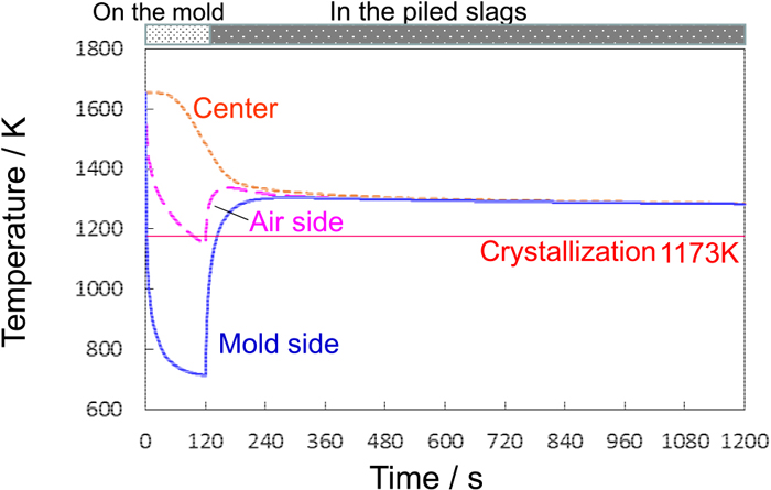
Figure 16 shows the time-dependent change of the temperature on the mold side, in the center and on the air side of the slag cooled in the interior of the slag pile. As above, the slag was charging to the mold at 0 s and discharged into the pit at 120 s. When the slag is held inside the slag pile, the temperature difference in the slag becomes small due to heat conduction in the slags, and the temperature became substantially uniform at 300 s. Then, at 144 s, the temperature on the mold side of the slag reached the crystallization temperature of 1173 K.22) Figure 17 shows the calculated results of the principal thermal stress generated at that time, where positive and negative values indicate tensile stress and compressive stress, respectively. While the slag is on the mold, a maximum principal thermal stress of approximately 350 MPa arose on the mold side and air side of the slag. Inside the slag pile, the stress in the solidified slag gradually decreased, and at 342 s, the maximum principal stress had decreased to less than tensile strength of the slag, i.e., 8 MPa. Figures 18 and 19 shows the the temperature and thermal principal stress distribution in the thickness direction of the slag at 600 s and 3600 s. Since the temperature inside the slag is almost constant and the thermal stress is substantially 0 MPa at all positions in the thickness direction, it can be inferred that cracks generally do not occur in slag which is held inside the slag pile. Moreover, the calculated results indicated that large tensile stress is applied in both cases a) and b) while the slag is held on the mold, but cracks were not observed in the recovered crystal slag shown in Fig. 3(a). This suggests that thermal stress does not induce cracking from 0 s to 240 s so long as the center of the slag is in an unsolidified condition.
Based on the results presented above, the mechanism of crack generation in the plate-shaped solidified slag produced by the continuous solidification process will be explained based on Fig. 20. In the case of the slag with a glass layer (Fig. 20(a)) held on the surface of the piled slag, where it is exposed to the atmosphere, the glassy surface layer is retained without undergoing crystallization because the temperature on the mold interface side of the slag only rises to 1000 K. Since tensile stress of 8 MPa or more is generated on the mold interface side due to the temperature difference between the surface and the interior of the slag, cracks are generated from the mold side toward the interior of the slag. Then, cooling proceeds while this temperature difference is maintained, and the initial cracks grow due to the continuing action of tensile stress. For this reason, slags that retain the glassy quality have low impact resistance due to the cracks that exist in the slag, and the slag is brittle.

On the other hand, in the crystal slag (Fig. 20(b)) held inside the slag pile, the temperature difference in the thickness direction of the slag is eliminated by heat conduction, the temperature rises to 1173 K or higher, and the glass layer is crystallized. At the same time, cracks do not occur because cooling proceeds under a condition in which the internal stress in the slag does not exceed the tensile strength of blast furnace slag, as shown in Fig. 6. In this case, slag with high impact strength can be obtained because cracks do not occur.
The ratio of slag with a glass layer, which contains cracks, can be reduced by piling the solidified slags so as to minimize the ratio of slags located at the outermost surface as far as possible. Accordingly, in this process, it is important to equalize the internal temperature of the solidified slags by utilizing the heat possessed by the slags themselves by piling the slags.
As discussed above, the mechanism of crack generation in the continuous solidification process of blast furnace slag could be explained convincingly by only the thermal stress behavior of the slags.
5. Conclusion
The continuous solidification process of blast furnace slag was developed, and the following points concerning the effect of the thermal history of the produced solidified slags on slag crack generation behavior were clarified.
(1) The slags produced by this process are mostly crystal slags, in which the entire slag is crystalline, but also include a small amount of slag with a glass layer, which has a 2 mm vitrified surface layer. Cracks occur in solidified slags with a glass layer.
(2) From a measurement of the impact strength (shatter strength) of the slags, the slag with a glass layer does not shatter to a size of less than 20 mm. When crushing slags to produce coarse aggregate for concrete, the cracks that exist in the solidified slags can be sufficiently removed and do not affect the strength of the coarse aggregate.
(3) The thermal stress analysis revealed that a temperature gradient occurs in the interior of the slag with a glass layer on the exposed surface of the piled slag in the slag pit. Since a temperature difference of approximately 200 K exists in these slags during cooling, tensile stress of 70 MPa is generated at the side that was in contact with the mold, and cracks occur because this tensile stress is greater than the tensile strength of the slag (8 MPa). On the other hand, the crystal slag is retained inside the slag pile, where the temperature difference in the slag interior is effectively eliminated by heat conduction from the surrounding slags. Since the stress generated under this condition is smaller than the tensile strength of the slag, cracks are not generated.
References
- 1) Y. Ta, T. Hoshino, H. Tobo and K. Watanabe: ISIJ Int., 59 (2019), 1917.
- 2) Y. Ta, T. Hoshino, H. Tobo and K. Watanabe: Tetsu-to-Hagané, 104 (2018), No. 11, 708 (in Japanese).
- 3) H. Tobo, Y. Miyamoto, K. Watanabe, M. Kuwayama, T. Ozawa and T. Tanaka: ISIJ Int., 54 (2014), 704.
- 4) Y. Ta, H. Tobo and K. Watanabe: JFE Tech. Rep., (2018), No. 23, 97.
- 5) K. Nakanishi, Y. Murata and Y. Ta: JFE Tech. Rep., (2017), No. 40, 62 (in Japanese).
- 6) K. Nakanishi, B. Ou and Y. Ta: Proc. Japan Concrete Institute, Vol. 38, JCI, Tokyo, (2016), 75 (in Japanese).
- 7) M. Watarai, K. Teranishi and H. Nonaka: Proc. Japan Concrete Institute, Vol. 34, JCI, Tokyo, (2012), 1210.
- 8) O. S. Narayanaswamy: J. Am. Ceram. Soc., 61 (1978), No. 3–4, 146.
- 9) A. Yuse and M. Sano: Phys. D, 108 (1997), 365.
- 10) S. Sakka, M. Wada and M. Tashiro: J. Ceram. Soc. Jpn., 69 (1961), 35.
- 11) JIS A 1113: 2018, Method of test for splitting tensile strength of concrete (in Japanese).
- 12) JIS R 1602: 1995, Testing methods for elastic modulus of fine ceramics (in Japanese).
- 13) JIS R 1605: 1995, Testing methods for elastic modulus of fine ceramics at elevated temperature (in Japanese).
- 14) M. Mellor: Proc. Second International Conference on Permafrost, National Academy of Sciences, Washington D.C, (1973), 334.
- 15) G. W. Mclellan and E. B. Shand: Glass Engineering Handbook, Third Edition, Mcgraw-Hill Book Company, New York, (1984), 2-12.
- 16) I. Takeuchi: Thermal Stress, Nisshin Publisher, Tokyo, (1989), 14 (in Japanese).
- 17) K. Ogino and J. Nishiwaki: Physical and Chemical Data Book for Iron and Steelmaking, ISIJ/JSPS, Tokyo, (2006), 350.
- 18) Y. Kang and K. Morita: ISIJ Int., 46 (2006), 420.
- 19) N. Sakata, D. Hayashi, G. Sakai and T. Miyagawa: Proc. Japan Concrete Institute, Vol. 32, JCI, Tokyo, (2010), 191.
- 20) K. Shinobe, N. Nito, Y. Aikawa and E. Sakai: Cem. Sci. Concr. Technol., 71 (2017), 68 (in Japanese).
- 21) Y. Miyazawa, H. Sugiyama and T. Yokomuro: J. Struct. Constr. Eng. (Trans. AIJ), 82 (2017), 1517 (in Japanese).
- 22) Y. Kashiwaya, T. Nakauchi, K. S. Pham, S. Akiyama and K. Ishii: ISIJ Int., 47 (2007), 44.