Social and Environmental Engineering
Selective Separation of Metallic Fe Remaining in Slags Using Electrical Pulse Disintegration
2021 年 61 巻 5 号 p. 1725-1735

詳細
2021 年 61 巻 5 号 p. 1725-1735
Metallic Fe (hereinafter abbreviated as M.Fe) is suspended in steelmaking slags due to the stirring action during blowing and is mainly recovered via pulverization, classification, and magnetic separation. However, steelmaking slags are hard, and it is difficult to transform irregular-shaped and fine M.Fe in slags into free particles through the conventional pulverization method, which requires a large energy consumption. In this study, pulverization and separation experiments of steelmaking slags were performed using electrical pulse disintegration, which is completely different from the conventional pulverization method and capable of causing preferential fracture at the heterophase interface. As a result, several free particles of M.Fe with almost no slag attached were obtained from the coarse and fine pulverized particles. In addition, the electric field analysis results of a system where spherical M.Fe exists in a slag show that electric field concentration occurs in the front and back directions of the external magnetic field. The findings also show that a fracture can occur at the interface between the M.Fe and slag due to the combination of increased discharge probability, concentration of thermal energy, and generation of the Maxwell stress. Furthermore, the larger the pulverized mass, the higher the pulverization efficiency. In sum, electrical pulse disintegration may be advantageous for actual operations, where large quantities of oxides employed in the steel industry, such as steelmaking slag, spent refractories, and raw materials, should be treated in a short time with low energy consumption.
In steel smelting, impurities derived from raw materials are mainly removed as slags. Steel slag is roughly classified into blast furnace slag, which is produced by slowly dripping through coke packed bed in the blast furnace, and steelmaking slag, which is produced by forced stirring in various steelmaking processes. Steelmaking slags suspend approximately 10%–40% of metallic Fe (hereinafter abbreviated as M.Fe) due to the stirring action during smelting and leaching in the smelting facility.1) Accordingly, steelmakers recover coarse M.Fe in steelmaking slags through multi-stage pulverization, classification, magnetic separation, and specific gravity separation and produce slag products of various particle sizes.1,2) However, a considerable amount of irregular-shaped and fine M.Fe likely remains in steelmaking slags because it is hard and the pulverized grain size is several tens of millimeters.
To improve the recovery rate and quality of M.Fe, it is important to separate M.Fe from slags as free particles in the pulverization process. However, in the conventional pulverization method, compressive and impact forces are randomly applied to steelmaking slags, so selective fracture at the M.Fe–slag interface is unlikely to occur. In some cases, coarsely separated M.Fe is further ground to remove adhering slags and improve its quality.3) In addition, the energy efficiency in pulverization is generally only less than 1%, and a considerable amount of electricity is consumed to pulverize a large amount of steelmaking slags. Electrical pulse disintegration is a pulverization method that can solve the problems encountered in conventional pulverization methods. When the object to be pulverized is allowed to stand in water and a high-voltage pulse is applied, a discharge is generated. The electric current preferentially passes through the interface of the constituent phases. Then, the object is pulverized by the accompanying ablation or shock waves, and many free particles in each phase are generated. In addition, although the voltage is high, the time for the current to flow in one pulse irradiation is on the order of microsecond, so the energy consumption is reported to be approximately 1/10 to 1/100 of that of the conventional pulverization method.4) Industrial-scale equipment for electrical pulse disintegration has been commercially available, and studies have so far been conducted to separate desired crystal phases and parts from gemstones,5) ores,6) electronic substrates,7) and spent refractories.8) Particularly, in Japan, centering on “High-Efficiency Rare Elements Extraction Technology Area in Tohoku Innovative Materials Technology Initiatives for Reconstruction” (finished on March 31, 2017), active research on the destruction mechanism and verification test for a highly efficient separation and recovery of parts with concentrated rare metals, such as motors and capacitors mounted on waste electronic boards, has been conducted.9,10,11) However, the verification of the destruction mechanism is difficult and has not been completely clarified because electrical pulse disintegration involves a discharge phenomenon that occurs in solids and liquids. In addition, pulverization for a mixture of metal and oxide, such as steelmaking slags, in which M.Fe is dispersed, has hardly been attempted.12,13)
In this study, a pulverization experiment of a steelmaking slag via electrical pulse disintegration was performed, and the influence of pulverization conditions on the particle size distribution of the pulverized product and the separability of M.Fe were investigated. In addition, the preferential fracture mechanism of the M.Fe–slag interface was verified by an electric field analysis.
A steelmaking slag generated by a blast furnace manufacturer was unevenly crushed to a diameter of approximately 20–50 mm (10–40 g per piece) and used as a sample. Table 1 shows the composition of the powder obtained by pulverizing the sample to 1 mm or less with a stamp mill. However, the obviously massive M.Fe particles generated during pulverizing were excluded. Steelmaking slag is expected to be derived from the dephosphorization process with a basicity (CaO/SiO2) of 1.8. The amount of M.Fe contained in the steelmaking slag widely varies, and it cannot be easily grasped before crushing. As will be clarified later from the results of this study, M.Fe was converted into free particles with almost no pulverization involved.
| CaO | SiO2 | T.Fe | MnO | MgO | Al2O3 | P2O5 | |
|---|---|---|---|---|---|---|---|
| mass% | 41.5 | 23.5 | 16.3 | 4.3 | 3.1 | 1.7 | 1.6 |
A sample containing high amounts of M.Fe produces a small amount of slag powder. Therefore, when M.Fe particles with a mass of 30% or more were obtained in the pulverized products, the result of the re-pulverization of other samples under the same conditions was adopted as data. In total, approximately 5% of the samples contained more than 30% of the mass of M.Fe particles.
2.2. Electrical Pulse DisintegrationThe electrical pulse disintegration equipment Lab S 2.0 manufactured by SELFRAG was used for the pulverization experiment. Figure 1 shows a schematic diagram of the area around the pulse irradiation section. The pulverization pot was filled with 3 L of tap water, and 20–200 g of the steelmaking slag were submerged. The steelmaking slag was pulverized under the following conditions: an electrode distance of 10–40 mm, a voltage of 100–180 kV, a number of pulse irradiations of 10–300 times, and a discharge frequency of 5 Hz (pulse irradiation: 5 times/s). Conditions other than the number of pulse irradiations are within the range restricted by the specifications of this device. After pulverization, the steelmaking slag suspension was filtered, dried, and classified into 21 particle groups using various mesh sieves (openings: 32, 74, 100, 125, 150, 177, 212, 250, 300, 355, 425, 500, 600, 710, 850, 1000, 2000, 2800, 4000, 5600 μm).
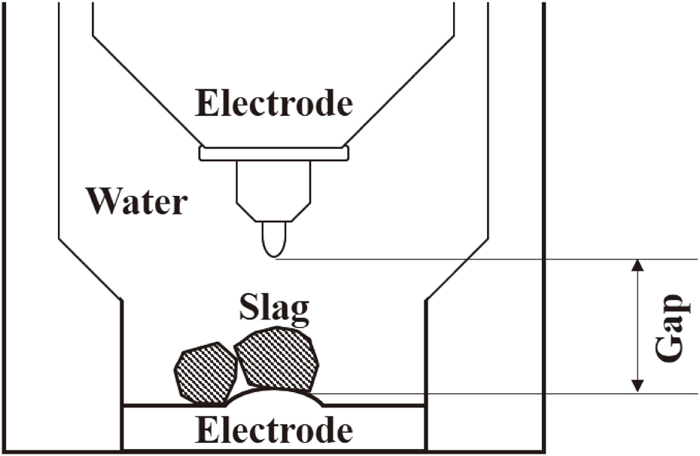
Schematic diagram of the pulse irradiation setup for electrical pulse disintegration.
Because the mass and size of the M.Fe particles contained in the steelmaking slag sample are different from each other, there is a large variation in the normal particle size distribution, and it is difficult to evaluate the pulverization situation. The specific surface area of the entire particle increases with the progress of pulverization, and a correlation is assumed to exist between the surface area and energy consumption. Therefore, we decided to process the experimental results based on the relationship between the surface area per unit mass and the energy consumption per unit mass of the pulverized products. Because the slag contains many voids and irregularities, the increase in the specific surface area is overestimated when the surface area of the pulverized particles is directly measured. In this study, the specific surface area generated via pulverization was estimated by the following calculation, ignoring voids and irregularities on the particle surface. First, it was assumed that all the particles were spheres with a central particle size in each particle group. For example, a particle group of 250 μm < φ < 300 μm was assumed to have a particle size of 275 μm (however, a particle group of 5600 μm < φ was assumed to have a particle size of 6000 μm).
The mass mi of a certain particle group i is expressed by Eq. (1) using the central particle diameter li, average density ρi, and number of particles ni.
| (1) |
The surface area Si of a certain particle group i is expressed by Eq. (2).
| (2) |
The total surface area Si of the 21-particle group is the surface area S generated via pulverization and is arranged as shown in Eq. (3) using Eqs. (1) and (2).
| (3) |
The average density ρi varies from particle groups to particle groups, but for simplification, it is assumed to be constant at an apparent density of 4.73 g/cm3 for the unpulverized sample measured by the Archimedes method. The specific surface area is the value S/m obtained by dividing the surface area S by the total mass m of the entire particle group.
2.3. Stamp MillingA pulverization experiment of a steelmaking slag using a stamp mill (Nitto Kagaku, ANS-143PS) was also conducted and compared with the electrical pulse disintegration. The steelmaking slag was placed in a stainless-steel mortar with an inner diameter of φ143 mm × 155 mm and pulverized for a predetermined time with a stroke of 60 mm and a stroke number of 120 times/min. After the pulverization of approximately 20 g of the steelmaking slag for 20 to 1800 s in the preliminary experiment, the progress of pulverization slowed down at approximately 150 s. In this study, the pulverization time was fixed at 150 s, and only the results of pulverizing 20–200 g of the steelmaking slag with a stamp mill are shown. The energy consumption (J) of the stamp mill was calculated by multiplying the power consumption of the equipment used (53 W) by the pulverization time (s). Therefore, the energy consumption used during the pulverization with a stamp mill for 150 s is 7950 J. After the pulverization, the sample was classified into 21 particle groups, as described in Section 2.2.
2.4. Magnetic SeparationThe pulverized product obtained by the pulverization experiment was sprayed on a smooth paper surface for each particle group and covered with a petri dish with a height of 8 mm. The ferrite magnet (φ20 mm × 5 mm; surface magnetic flux density B = 0.075 T) was slid on the petri dish to collect particles adhering to its surface. The magnetic flux density B at a point 8 mm away from the center of the ferrite magnet was 0.021 T, and the magnetic field gradient ∂B/∂x was 3.7 T/m. The particles remaining on the paper were re-sprayed, and the same operation was repeated for 5 times. The particles adhering to the surface of the petri dish were collected as magnetized materials, and the particles remaining on the paper surface until the end were collected as non-magnetized materials. In the particle group with a particle size of 5600 μm or more, which is the largest in this study, some particles have a diameter of more than 8 mm. These particles were separated into magnetized and non-magnetized materials by directly placing them in contact with ferrite magnets without using a petri dish. The magnetic field gradient ∂B/∂x near the center of the ferrite magnet was 8.3 T/m. The magnetized materials were dissolved by the Br–CH3OH method,14) and the M.Fe concentrations were quantified. In addition, the magnetizations of the M.Fe and slag were measured using a vibrating-sample magnetometer.
2.5. Measurement of the Slag PermittivityThe electrical pulse disintegration behavior of the steelmaking slag was estimated through an electric field analysis, as will be explained in the next section. As parameters required for the calculation, the frequency dependence of the permittivity and electrical conductivity of the M.Fe and slag were measured by the AC impedance method.
A steelmaking slag sample was cut to a thickness of approximately 1 mm using a precision cutting machine, and a sample piece containing no M.Fe was inserted into a parallel-plate capacitor-type sample cell consisting of two brass disks with a diameter of φ10 mm. The cell was connected to an LCR meter (IM3536, Hioki E. E.) and a self-made current-voltage impedance analyzer with a 4-terminal pair connection, where the impedance
To investigate the state of electric field concentration at the boundary between the M.Fe and slag, the electric field intensity distribution was calculated for the boundary conditions that can be solved analytically. Electric charges tend to accumulate in places where the electric field is more concentrated than the surroundings, and a high probability exists that an electric discharge will occur. A significant electric field concentration is expected at the boundaries between M.Fe and slag because they have completely different electrical characteristics and clear boundaries. Although some attempts have been made to elucidate the discharge phenomenon of electric pulse disintegration by numerical calculation,6,11) it was verified with a simple two-dimensional system in this study.
We consider a spherical region with a complex permittivity

Boundary conditions for the electric field analysis.
At this time, if the electric field intensity distribution
| (4) |
Here, the coordinates
Here,
| (5) |
Each of the real and imaginary parts become Eqs. (6) and (7), respectively:
| (6) |
| (7) |
In the electrical pulse disintegration of this study, the voltage between the electrodes was raised from 0 to 100 kV in a short time of approximately Δt ≈ 0.1 μs to generate an electric discharge. Because the electrode spacing is several tens of millimeters, when converted to an electric field, ΔE ≈ 105 V/m was applied. If the time change in the electric field during this period is linearly approximated, then it can be regarded as the external electric field E(t) ≈ (ΔE/Δt)t. Furthermore, if the limit of 2πft ≪ 1 is taken for the external AC electric field E0sin (2πft), then E0sin (2πft) ≈ 2πE0ft. Therefore, the electric field distribution generated by the electrical pulse disintegration was reproduced by the short-time limit of the result when an AC electric field was applied. If ΔE ≈ E0, then the frequency is approximately f ≈ 1/(2πΔt). Because the duration of the one pulse irradiation in the electrical pulse disintegration is approximately Δt ≈ 0.1 μs, the frequency can be set to approximately f ≈ 1 MHz. Therefore, the value of the complex permittivity at 1 MHz was used to calculate the electric field intensity distribution.
Because the duration of the one pulse irradiation in the electrical pulse disintegration is approximately Δt ≈ 0.1 μs, the frequency can be set to approximately f ≈ 1 MHz.
Electrical pulse disintegration requires a strong electric field that causes a dielectric breakdown in the water and steelmaking slag in the pot and initiates an electric discharge. Therefore, the occurrence of a discharge depends on the combination of the electrode distance and applied voltage. Therefore, pulse irradiation was performed for 10 times with each combination of an electrode distance of 10–40 mm and an applied voltage of 100–180 kV, and the number of successful discharges was investigated. This condition was adopted because the discharge phenomenon includes a stochastic element, and the discharge rarely fails even under strong electric field conditions. Table 2 summarizes the results of the experiments when the pulverization pot was filled with 3 L of tap water and nothing and when approximately 20 g of the slag were placed on the electrode. Of the 10 pulse irradiations, 10-9 successful discharges are shown as A, 8-1 as B, and 0 as C. Because the electrodes of the pulverization equipment are a pair of rod-shaped and disk-shaped stainless steels, the electric field distribution formed is non-uniform. However, the larger the electrode distance and the lower the applied voltage, the smaller the electric field, as in the case of parallel plate electrodes. In fact, when nothing was placed on the electrode, no discharge was performed under weak electric field conditions where the applied voltage was 130 kV or less at an electrode distance of 30 mm and an applied voltage of 150 kV or less at a distance of 40 mm. Furthermore, when the steelmaking slag was placed on the electrode, it was possible to discharge even under some conditions where the electric field was weak. The steelmaking slag was composed of the conductor M.Fe and dielectric slag. Applying the general theory of capacitors, it can be interpreted that the steelmaking slag was inserted between the electrodes, causing the surrounding electric field to rise and making it easier to discharge. Therefore, we decided to perform the following experiment under the condition of A where the discharge was stable: the applied voltage was changed when the electrode distance was fixed at 10 mm, or the electrode distance was changed when the applied voltage was fixed at 180 kV.
| Voltage/kV | Gap between the electrods/mm | |||||||
|---|---|---|---|---|---|---|---|---|
| 10 | 20 | 30 | 40 | |||||
| Without slag | With slag | Without slag | With slag | Without slag | With slag | Without slag | With slag | |
| 100 | A | A | A | A | C | B | C | C |
| 130 | A | A | A | A | C | A | C | C |
| 150 | A | A | A | A | B | A | C | A |
| 180 | A | A | A | A | A | A | B | A |
Figures 3 and 4 show the results of the electrical pulse disintegration of approximately 20 g of the steelmaking slag under an applied voltage of 100–180 kV and pulse irradiation times of 10–300 times with the electrode distance fixed at 10 mm. The results showed that the larger the applied voltage and the number of pulse irradiations, the larger the energy consumption. In addition, the specific surface area of the pulverized material increased with energy consumption along approximately one curve, regardless of the applied voltage. In other words, the applied voltage is related only to the energy consumption per pulse irradiation applied to the steelmaking slag.

Effects of number of irradiation pulses on particle size distribution.

Effect of voltage and number of irradiation pulses on the specific surface area of particles obtained via electrical pulse disintegration.
Figures 5 and 6 show the results of the electrical pulse disintegration of approximately 20 g of the steelmaking slag under an applied voltage of 180 kV and pulse irradiations of 10–300 times with the electrode distance changed from 10 to 40 mm. The results showed that the larger the electrode distance, the larger the energy consumption per pulse irradiation. At distances between the electrodes of 20–40 mm, no significant difference was found in the increase curve of the specific surface area. Furthermore, at an electrode distance of 10 mm, the rate of increase in the specific surface area with respect to energy consumption tended to be high. When the electrode distance is 10 mm, the energy consumption is approximately half that of 40 mm, but the discharge range is narrow. The sample pulverized in the experiment in this section was small, approximately 20 g. Therefore, there is a high probability that particles will exist within the discharge range, and it is presumed that they were efficiently pulverized with low energy consumption. For actual operations, it is desirable to set a wide electrode distance from the viewpoint of the degree of freedom in the size of the pulverized object and the treatment efficiency. Therefore, the pulverization experiment was conducted by fixing the electrode distance to 40 mm and the applied voltage to 180 kV and increasing the pulverized mass, as presented in the next section.

Effects of the electrode distance (gap) on particle size distribution.

Effect of the electrode distance (gap) on the specific surface area of particles obtained via electrical pulse disintegration.
A total amount of 20–200 g of the steelmaking slag were pulverized via electrical pulse disintegration and stamp milling. The conditions for the stamp milling were pulverization for 150 s and energy consumption of 7950 J, as described in Section 2.3. The conditions for electrical pulse disintegration were an electrode distance fixed at 40 mm, applied voltage of 180 kV, and pulse irradiations with a target of 7950 J. In total, the number of pulse irradiations was 74–95 times, and the energy consumption was 7948–7976 J. The energy consumption per pulse irradiation increased or decreased by approximately 30% even under the same conditions, and such variations occurred because the discharge phenomenon is nonlinear and involves stochastic factors.
Figures 7 and 8 show the effect of the pulverized mass on the surface area calculated from the particle size distribution of the pulverized particles. In stamp milling, the specific surface area significantly decreased as the pulverized mass increased, and the impact force acts only around the area where the hammer hits. Therefore, as the pulverized mass increased, the probability of the hammer colliding with the steelmaking slag decreased. In addition, the impact force was mitigated by the reduction of the stroke and the generated pulverized material. In electrical pulse disintegration, the surface area, that is, the particle size distribution, did not change significantly with the increase in pulverized mass. First, the direct destruction occurred in the discharge path. It is expected that the larger the pulverized mass, the higher the probability that the steelmaking slag is present on the discharge path, and more fractures occur. In addition, because the shock wave secondarily generated by the discharge propagates throughout the water, the larger the pulverized mass, the more the impact force is applied to a large number of particles in one discharge, and the more the finer particles are promoted.

Effects of pulverized mass on particle size distribution of particles obtained by electrical pulse disintegration (Gap: 40 mm, Voltage: 180 kV, Number of irradiation pulses: 74–95 times) and stamp mill (Pulverizing times: 150 s). Energy consumption was 7948–7976 J.

Effect of the pulverized mass on the specific surface area of particles obtained via electrical pulse disintegration (gap: 40 mm, voltage: 180 kV, number of irradiation pulses: 74–95 times) and stamp milling (pulverization times: 150 s). Energy consumption was 7948–7976 J.
Figure 9 shows the relationship between the energy consumption and pulverized mass. Because the energy consumption was fixed at approximately 7950 J, the larger the pulverized mass, the smaller the energy consumption per unit mass. For example, when the pulverized mass was increased from 20 g to 200 g, a 10-time increase, the energy consumption per unit mass was reduced to approximately 1/10. Furthermore, as mentioned above, in the electrical pulse disintegration, no significant difference in the surface area was confirmed even if the pulverized mass increased. Therefore, the larger the pulverized mass, the higher the pulverization efficiency, at least under the conditions of this study. The discharge frequency set in this study was 5 Hz (pulse irradiation frequency: 5 times/s), and the pulverization time was only 20 s even when the pulse irradiation frequency was 100 times. These results suggest that electrical pulse disintegration may be an advantageous pulverization method for actual operations, where it is necessary to treat a large amount of steelmaking slags in a short time with low energy consumption.

Effect of the pulverized mass on energy consumption.
Figure 10 shows examples of particles obtained from the electrical pulse disintegration. Figure 10(a) is a photograph of characteristic M.Fe particles that were visually sorted. Several free particles with almost no slag were obtained, although the surface was covered with an iron oxide film as M.Fe is easily oxidized. There were various shapes, such as spheres, those connected by thin parts, and hollow ones, suggesting that selective pulverization occurred at the interface between the M.Fe and slag. In the conventional pulverization method, the probability that a free particle having such a complicated shape is generated is low without an additional treatment, such as attrition. Figure 10(b) is a photograph of a particle group with particle sizes of 100 μm or less taken with a three-dimensional laser microscope. Few fine M.Fe free particles were obtained. In addition to M.Fe, different colors of free particles, such as white, brown, black, and yellow, were observed, suggesting that selective pulverization occurred between different oxide crystalline phases that make up the slag. Kubo et al. proposed a mutual separation process of oxide phases containing phosphorus, iron, and manganese that make up a steelmaking slag via pulverization and a strong magnetic field.16) The application of electrical pulse disintegration may improve the separation performance of components other than M.Fe.

Pulverized particles obtained via electrical pulse disintegration. (Online version in color.)
A sample (Section 3.1.3) obtained by pulverizing 200 g of the steelmaking slag via electrical pulse disintegration or stamp milling was magnetically separated for each particle group. Figure 11 shows the M.Fe concentration in the magnetized materials of each particle group. In the coarse particle groups (5600 μm < φ) of the sample obtained via stamp mill pulverization, a large part of the unpulverized steelmaking slag remained, so the M.Fe concentration in the magnetized materials (plotted at 6000 μm in Fig. 11) was low. In addition, there were many particles in which the slag and M.Fe were not separated even in the particle groups of φ < 5600 μm where pulverization proceeded, and the M.Fe concentration tended to be low as a whole. In the electrical pulse disintegration, almost all of the magnetized materials obtained from the particle groups with particle sizes of 2000 μm < φ were free particles of M.Fe. In the particle groups with particle sizes of 2000 μm or less, the amount of magnetized slag increased during the magnetic separation process, and the M.Fe concentration was approximately 10–60 mass% in the electrical pulse disintegration and stamp milling. The recovery rate of M.Fe as magnetized materials was 97.7% by electrical pulse disintegration and 46.9% by stamp milling.

Fe concentration of each magnetized particle group obtained through magnetic separation.
Figure 12 shows the magnetization curves of the M.Fe and slag. M.Fe formed a typical ferromagnetic hysteresis, and the saturated mass magnetization reached 216 emu/g. This is a value close to the saturated mass magnetization of 220 emu/g of pure iron described in Reference 17. The slag formed a hysteresis in which ferromagnetic and paramagnetic substances were mixed, and the maximum mass magnetization in the measurement range was 92 emu/g. When the external magnetic field was maximum, the mass magnetization of M.Fe was more than twice as large as that of the slag. However, the difference became smaller as the external magnetic field became weaker, and the mass magnetizations of both were reversed at approximately 0.6 kOe.

Magnetization curves of iron and slag particles.
The relationship between the force acting on the particles and the particle size in the magnetic separation was calculated. A schematic diagram of the calculated system is shown in Fig. 13. The magnetization and magnetic field gradient vary with the distance between the magnet and the particles. In the magnetic separation experiment, it was covered with a petri dish with a height of 8 mm, and the distance between the magnet and smooth paper surface was kept constant. However, the calculation of the acting magnetic force is complicated because the distance to the magnet differs depending on the particle size or the location inside the particle. The particles were regarded as a point mass system, and the calculation was performed when the distance between the magnet and the particles was 8 mm (B = 0.021 T, ∂B/∂x = 3.7 T/m) and 0 mm (B = 0.075 T, ∂B/∂x = 8.3 T/m). If the force acting on a spherical particle with a diameter of l and a mass of m is limited to the magnetic force Fmag, p by the magnet and gravity mg, the particles are magnetized when the magnetic force exceeds gravity. The magnetic force per unit mass Fmag, kg (N/kg) is described by Eq. (8), assuming that the magnetic field acts only in the one-dimensional direction.18)
| (8) |

Schematic diagram of the experimental conditions for the magnetic separation and the system that calculates the force acting on a particle.
Here, M (emu/g) is the mass magnetization, and B (T) is the magnetic flux density.
Assuming that 10 kOe = 1 T, when the magnetization M at 8 mm and 0 mm was read from the magnetization curves shown in Fig. 12, the M.Fe was 8.60 and 28.7 emu/g, respectively, and the slag was 10.1 and 26.7 emu/g, respectively. By substituting these values, Fmag, kg was calculated.
The mass m (g/particle) of one spherical particle with a diameter l is expressed by the relationship of Eq. (9) using the density ρ (g/cm3).
| (9) |
The density ρ was 7.80 g/cm3 for the M.Fe and 4.06 g/cm3 for the slag. For these densities, the values measured by the Archimedes method for the free particles of the M.Fe obtained from the magnetized materials and the dissolution residue of the magnetized materials by the Br–CH3OH method were adopted. From Eqs. (8) and (9), the magnetic force acting on one spherical particle Fmag, p (N/particle) is calculated by Eq. (10).
| (10) |
In sum, the force acting on one spherical particle Fp (N/particle) is calculated by Eq. (11).
| (11) |
The calculation results are shown in Fig. 14. At the magnetic flux density B where the distance between the magnet and the particle was 8 mm, the mass magnetization was larger in the slag than that in the M.Fe, as shown in the magnetization curve (Fig. 12). However, because the densities of the two are different, the magnetization (volume magnetization) of particles of the same size is larger for M.Fe than for slag, and the magnetic force acting on M.Fe is proportionally stronger than that on slag. Therefore, the force acting on the particles under any magnetic field condition and particle size is stronger for M.Fe particles than for slag particles. The smaller the particle size, the smaller the amount of magnetic substance and the lower the magnetic force acting on the particles. When the magnetic force is weak, the movement of the M.Fe particles is easily obstructed by the surrounding slag particles. In addition, agglomeration is likely to occur, especially in particle groups with particle sizes of approximately 100 μm or less, and the movement of M.Fe particles is more likely to be obstructed. In addition, the smaller the particle size and magnetic field gradient, the smaller the difference in the forces acting on the M.Fe and slag, so the probability of being attracted to both of the magnet increases. Therefore, to selectively magnetically separate M.Fe from fine particles of the slag mixed with ferromagnetic and paramagnetic substances, it is necessary to design a magnetic field with high accuracy in addition to the efficient generation of free particles. In the current slag treatment, dry pulverization and drum-type magnetic separation are mainly adopted. According to information from several industry insiders, only magnetized materials separated from particle groups with particle sizes of approximately 1000 μm or larger are used as iron sources. One of the major factors that determine this cut point is the difficulty of magnetic separation on the fine particle side. The magnetic separation method in this experiment also has different magnetic field conditions, but there is room for improvement because it has a similar form.

Relationship between the force acting on one particle and the particle size obtained by the calculation result.
The current slag treatment is a dry process, whereas the electrical pulse disintegration is a wet process, in which a slag is submerged and pulverized. As confirmed in Fig. 10, the electrical pulse disintegration tends to generate free M.Fe particles even if they are fine particles. Therefore, the fine particles can be separated from one another with higher accuracy than the current method by applying wet magnetic separation or specific gravity sorting.
3.3. Results of the Electric Field AnalysisFigure 15 shows the frequency dependence of the permittivity ε′ and electrical conductivity σ (= ωε0ε″) of the slag obtained by the AC impedance method. A large difference in the electrical characteristics was confirmed between the M.Fe and slag. The electrical conductivity of approximately 1 Hz, which corresponds to the DC characteristics, was approximately 10−8 S/m for the slag. Generally, the electrical conductivity of the M.Fe around room temperature is approximately 107 S/m19) regardless of the frequency, but it is approximately 1015 times different from the electrical conductivity of the slag. However, this difference gradually decreased as the frequency increased and decreased by approximately 1012 times at a frequency of approximately 1 MHz, which contributes to the electrical pulse disintegration. The permittivity of the slag at a frequency of 1 MHz was 13, and the electrical conductivity was 2.1 × 10⁻⁵ S/m.

Frequency dependence of permittivity ε′ and electrical conductivity σ of the slag phase in the steelmaking slag.
Such a difference in electrical characteristics between the M.Fe of the conductor and the dielectric slag causes non-uniformity of the electric field near the interface between the M.Fe and slag in the electrical pulse disintegration of the steelmaking slag. To examine this effect in detail, the distribution of the electric field strength was calculated based on Eq. (4). The complex permittivity of the slag is the value measured by the AC impedance method, i.e.,

Electric field intensity distribution when a uniform field is applied to a composite dielectric. (Online version in color.)
Figure 17 shows a schematic diagram of the lines of electric force and the stress acting around the M.Fe of the sphere. The lines of the electric force are curved toward the sphere and touch in the normal direction. The lines of electric force are curved toward the sphere and touch in the normal direction. The deformed lines of the electric force have the property of returning to a straight line, similar with rubber, and as shown by the arrows, stress (i.e., Maxwell stress) is generated in the directions of contraction and separation from each other. The Maxwell stress is considered to act outward from the surface of the M.Fe and to cause the slag to peel off as the electric lines of force cannot enter the M.Fe, which is a conductor. In this electric field analysis, the Maxwell stress and thermal energy generated by the discharge cannot be quantified, but both contribute positively to the fracture of the interface between the M.Fe and slag. In addition, M.Fe, which is a conductor, is hardly damaged electrically, and the shock wave generated by the dielectric breakdown of the slag and water is a major factor in pulverizing M.Fe. However, because M.Fe is tougher than slag, it is highly likely that it will not be pulverized and will remain in the form of a slag. The selective fracture of the steelmaking slag is expected to progress owing to the synergistic effect of the above factors.

Schematic about the directions of the Maxwell stress acting on M.Fe.
Based on the results of the electric field analysis, the results of the pulverization experiment were considered again. First, Figs. 3 and 4 show the results of the pulverizing steelmaking slag of the same mass by fixing the electrode distance to 10 mm and changing the applied voltage. When the applied voltage is high, the electric field strength concentrated at the interface between the M.Fe and the slag becomes relatively high. However, the outline of the lines of electric force hardly changes, and the effect on how the particles are broken is small. By contrast, the higher the applied voltage, the higher the frequency of dielectric breakdown and the greater the amount of power supplied. Therefore, it is considered that the pulverization tended to proceed with the increase in energy consumption instead of the applied voltage.
Next, Figs. 6 and 7 show the results of pulverizing the steelmaking slag of the same mass with the applied voltage fixed at 180 kV and the electrode distance changed. Because the average electric field strength decreases as the electrode distance increases, the frequency of the dielectric breakdown in the steelmaking slag is lower at 40 mm than that at 10 mm. In addition, the greater the electrode distance, the greater the dielectric breakdown of water. As the pulverized mass was small, it is presumed that the shock wave generated at this time could not act efficiently on the steelmaking slag. Therefore, it is considered that the greater the electrode distance, the more energy is consumed to obtain the same specific surface area.
Finally, Fig. 8 shows the results of pulverization with the electrode distance at 40 mm, applied voltage fixed at 180 kV, and mass of the steelmaking slag changed. When the mass of the steelmaking slag is large, the M.Fe that causes the electric field concentration and the slag with a high-permittivity increase between the electrodes forms a high electric field. As a result, the frequency of the dielectric breakdown inside the steelmaking slag increases. Furthermore, it is considered that the heavier the mass of the steelmaking slag, the longer the discharge path per pulse irradiation, and the higher the pulverization efficiency.
In this study, various experiments were conducted with the aim of selectively separating M.Fe contained in a steelmaking slag via electrical pulse disintegration. The findings are summarized below:
(1) The results of the electric field analysis show that electric field concentration occurs on the front and back of the M.Fe sphere with respect to the direction of the external electric field. Moreover, a fracture is likely to occur at the interface between the M.Fe and slag due to the combination of increased discharge probability, concentration of thermal energy, and generation of the Maxwell stress. In addition, because M.Fe is a conductor and has high toughness, it is hardly affected by discharges and accompanying shock waves and is likely to remain in the form of a slag.
(2) The electrical pulse disintegration of the steelmaking slag obtained a large number of free particles of M.Fe with almost no slag attached from the coarse and fine pulverized particles.
(3) Even if the pulverized mass increased with the same electrode distance, applied voltage, and number of pulse irradiations, no significant change was observed in the particle size distribution, and the energy consumption per unit mass decreased. Thus, electrical pulse disintegration may be advantageous for actual operations, where a large amount of steelmaking slags should be processed in a short time with low energy consumption. In the steel industry, many oxides exist that need to be pulverized, such as spent refractories and iron ore, in addition to steelmaking slags targeted in this study. If the method used here can be applied to these oxides, the effect of reducing the energy consumption will be huge.
(4) Through the magnetic separation of the sample obtained from the electrical pulse disintegration of the steelmaking slag, we found that almost all of the magnetized materials obtained from the particle group with particle sizes of 2000 μm or more were free particles of M.Fe. By contrast, in the particle groups with particle sizes of 2000 μm or less, the M.Fe concentration in the magnetized materials decreased.
By calculating the force acting on the particles in magnetic separation, we found that it is difficult to separate fine particles mixed with M.Fe and slags, which are ferromagnetic or paramagnetic substances, and a highly accurate magnetic field design is required. Electrical pulse disintegration is a method of submerging slags. Wet magnetic separation and specific gravity sorting are also promising options.
This work was supported by JSPS KAKENHI Grant Number JP20K05591 and ISIJ Research Promotion Grant. We would like to express our deep gratitude to Mr. Tomoaki Sakurai and Mr. Hiroshi Ishikawa of the former Institute of Multidisciplinary Research for Advanced Materials, Tohoku University. We received a great deal of support and advice from them for the electrical pulse disintegration. We would also like to thank the members of the Kubo Laboratory of Fukuoka Institute of Technology for helping us with the enormous amount of slag classification work.