Surface Treatment and Corrosion
Size Effect on Flow Field and Dynamic Deposition of Bottom Dross in a Molten Zinc Pot
2021 Volume 61 Issue 5 Pages 1633-1640
Details
2021 Volume 61 Issue 5 Pages 1633-1640
During the continuous hot-dip galvanizing process, the effect and mechanisms of production parameters on flow field and dynamic deposition behaviors of bottom dross are critical issues for solving problems on harmless accumulation and control technologies of bottom dross. In this paper, a combined method of numerical simulation and water modeling experiment is presented to investigate the effects of steel strip width and velocity on flow field and dynamic deposition of bottom dross in a zinc pot. The molten zinc flow in an industrial-sized model were numerically simulated by the computational fluid-dynamics method. A 1/5 reduced-scale physical water model is established to study deposition behaviors of bottom dross based on the theoretical framework of similarity. NaCl aqueous solutions and black particles of acrylonitrile butadiene styrene are employed as model fluid and bottom dross, respectively. The results show that the width of strip is a key factor for the intensity of two impact flows in the bath. The condition of interaction between two impact flows determines the accumulation morphology of bottom dross. The influence of the strip width on the deposition directon of bottom dross exhibits an obvious size effect. With the decreasing of strip width, the deposition direction of the scattered bottom dross under sink roll is gradually changed from backward to backward as well as forward. The velocity of strip has no significant impact on the flow characteristics, but shows a strong positive correlation with the intensity of flow field and the number of scatted bottom drosses.
The hot-dip galvanizing process is used to form a galvanizing coating on the surface of steel strip to prevent rusting and corrosion.1,2) In the hot-dip galvanization process, a steel strip of various widths and speeds is passed through a hot zinc tank for zinc coating. On exiting from the bath, the steel strip passes through a pair of gas knifes where the excess zinc solution is deflected back into the bath, leaving a thin coating on the steel sheet.3,4) Normally, it is very common that dross is formed due to metallic compounds and chemical reactions occurring in the zinc bath.5) The dross is sorted into top dross and bottom dross according to the density ratio of dross to liquid zinc. Top dross floats on the bath surface, while bottom dross sinks down in the bath. Dross, especially bottom dross, pick-up on strip is a common surface defect and not easy to overcome.6,7) Removing the dross is an efficient method to reduce the level of dross particles attached on the steel. A method for removing top dross is often known as skimming. Bottom dross are heaped up in the floor of the bath continuously. Halting production to clear bottom dross is a feasible method. However, frequent intervals would decline production efficiency. For the development of a fruitful method of removing bottom dross, it is essential to elucidate the motions of the dross in the bath.8)
Steel strip width, speed, and bath configuration can influence the flow field of the Al–Zn liquid and alloy component, as well as the dross formation, distribution and coating quality of the steel strip.9,10) Physical and numerical models are usually used to understand the flow characteristics in the process of hot-dip galvanizing bath.11,12,13,14) The simulations were commonly carried out by the computational fluid dynamics software using a model of mass and momentum with the k-ε turbulence model.15,16,17) Numerical simulation can be easier to eliminate scale effects encountered in physical model experiments and obtain data conveniently. It is more suitable for large-scale engineering problems and internal mechanism researches. Dross particles are transported by a liquid carrier, which involves problems on solid-liquid two-phase turbulent flow.18,19) Agglomeration of dross particles would occur during their movement within the bath, which plays a significant role in determining final particle size distribution. It is difficult to be taken into account in numerical simulations and water modeling experiments.3) As for flow field with dross, some parameters are difficult to be determined or need to be idealized.20) Thus, the influence of dross on the calculation is seldom considered in the numerical simulation.21,22,23) On the contrary, in physical model experiments, the motion and even the process of dross particles accumulation in the zinc pot could be observed directly.24,25,26,27) Water model experiments can be used to roughly describe the characteristic of the flow field by observing the trajectory of bottom dross, but it is no substitute for the numerical simulation study. Numerical simulations can provide a fairly comprehensive information of flow.28,29) Therefore, a water model experiment is used to investigate the dynamic deposition of bottom dross and numerical simulation of flow field is carried out to elucidate the formation mechanism of bottom dross morphology. These two methods can complement each other and contribute to investigations on the movement of dross.
Due to the close association with the coating quality of steel strip,30) the effect of two important factors, including the width and speed of strip, on the flow structure and dynamic deposition behaviors of bottom dross are investigated by applying numerical simulations and model experiments, respectively. In this paper, the flow field, the motion of bottom dross and the evolution of accumulation morphologies are considered and results can be applied to determine the mechanism underlying the association of molten zinc flow patterns with the dynamic deposition behaviors of dross, which facilitate the development of control technologies of bottom dross.
Physical model of flow is designed to ensure geometry similarity, kinematic similarity and dynamic similarity between model and prototype. The degree of geometric similarity (see Eq. (1)) should be established by rational analysis. Water is used to simulate liquid zinc owing to similar values of kinematic viscosity.14) In addition, the Reynolds number (Re) and the Froude number (Fr) are used to provide the dynamic similarity.
| (1) |
| (2) |
| (3) |
Where λ is the geometric similarity ratio between the model and its prototype, V the flow velocity, υ the kinetic viscosity of the fluid, g the gravity acceleration. The diameter of sink roll is selected as the characteristic length L.
If the flow regimes of the model and prototype are all in the second automatic simulation region,31) in which the magnitude of Re is more than 105 and the flow state of fluid is turbulent flow, the flow Reynolds number can be relaxed in both prototype and model. Thus, Froude number between model and the prototype is considered to be equivalent to make sure dynamic similarity between model and prototype.11,14)
Considering Eqs. (1) and (3), similitude between model and prototype on the basis of the Froude number is given by expression Eq. (4).
| (4) |
To study dynamic deposition behaviors of bottom dross, parameters of the fluid carrier and appropriate particles in a water model are further determined using a theoretical framework of similarity, which has already been proposed in our previous work.31) Under fully turbulent flow conditions for model, the particle Reynolds number and Shields number are adopted in this framework to ensure the similarity of dross motion between model and prototype.
The particle Reynolds number is important as considering the fall velocity of sediment.
| (5) |
Shields number θ is used for guaranteeing similarity of scaling sediment motion between prototype and model.
| (6) |
As described previously, Reynolds number is relaxed when Reynolds is high enough to establish fully turbulent conditions. In addition to geometric similarity, the physical model investigation on dynamic deposition behaviors of bottom dross in the zinc pot contains similarities of Froude number (see Eq. (4)), particle Reynolds number (see Eq. (5)) and Shields number (see Eq. (6)). They are employed to determine parameters of scaling physical model.
| (7) |
Based on the above discussion, a 1/5 scale water modeling experiment was established and a schematic diagram of experimental apparatus is shown in Fig. 1. The physical model below the liquid level consists of a snout, a sink roll, a scraper, two support rolls and an endless strip made by a PVC (Polyvinylchloride) resin soft board with a thickness of 1 mm. Over the liquid level, a balanced roll and a driving roll motivated by a DC (direct current) motor are added to drives the strip to obtain different strip speeds. A Cartesian coordinate system is placed at a corner of the liquid level. The main parameters of model and prototype are listed in Table 1. NaCl aqueous solution with density 1035 kg/m3 is selected as the model fluid. Black ABS (Acrylonitrile Butadiene Styrene) grains with a mean diameter of 1.2 mm and a density of 1040 kg/m3 are employed to simulate bottom dross. Two strip speeds and three strip widths are selected for the same as the real operation conditions. Moreover, temperature fluctuations would have an effect on the flow, especially in the regions away from the strip and immersion rollers. In these region, the forced convection is small.30) However, Deposition morphologies of bottom dross are mainly determined by forced convection, which is induced by the movement of belt and immersion rollers.31) Thus, temperature variation have been neglected in the present study. By contrast, it is should be taken into account in the researches mainly concerning temperature distribution.

Schematic diagram of experimental apparatus for a 1/5 scale water model.
| Prototype | 1/5 Model | |||
|---|---|---|---|---|
| Bottom dross diameter | Dinc,p | 0.3 mm | Dinc,m | 1.2 mm |
| Bottom dross density | ρinc,p | 7300 kg/m3 | ρinc,m | 1040 kg/m3 |
| Fluid density | ρf,p | 6700 kg/m3 | ρf,m | 1035 kg/m3 |
| Fluid kinematic viscosity | υf,p | 5.9×10⁻⁷ m2/s | υf,m | 1.05×10⁻⁶ m2/s |
| Strip velocity | Vp | 3.4, 1.7 m/s | Vm | 1.5, 0.75 m/s |
| Strip width | Wp | 1700, 1250, 800 mm | Wm | 340, 250, 160 mm |
| Bottom dross thickness | THp | 475 mm | THm | 95 mm |
The effects of different strip widths and speeds on the flow, as well as the dynamic deposition behaviors of bottom dross such as dispersion, transport and steady morphology have been investigated in order to optimize conditions for suppressing the dross particle pick-up on the steel strip. The initial height of bottom dross is 95 mm, which refers to the vertical distance between the upper flat surface of particle pile and the lowest point of the curved bottom of a zinc pot. Motions of bottom dross granules rolled up by flow field are recorded with a high-speed video camera and three-dimensional shapes of bottom dross are plotted with the help of a pair of laser levels.31) The measurement is performed after the experimental device running for three hours, in order to attain a steady morphology in the zinc pot.
The molten zinc space in the bath is classified, for convenience, into two parts as follows: flow region and accumulation region. Meanwhile, each part is further divided into several sub-zones (see Fig. 1). The flow region is used to represent the motions of bottom dross in the flow field and contains “flow region I”, “flow region II” enclosed with the belt, “flow region III” and “flow region IV” under sink roll. The accumulation region illustrates steady morphology of bottom dross in the bottom of the bath and includes “accumulation region A”, “accumulation region B” and “accumulation region C”. Furthermore, two of the four vertical boundaries of the tank which paralleled to the plane XOZ are called as side walls. The third boundary close to the front support roll is referred to as front wall. The fourth boundary overlapped with the plane YOZ is named as back wall.
The numerical solution considers a full scale model of the bath geometry, including all the hardwares immersed in the bath (strip, sink roll, support rolls, roll support arms, snout and scraper). The zinc flow is modelled as an incompressible fluid described by Navier-Stokes equations.32) The governing equations for fluid flow are represented as follows.
Continuity equation:
| (9) |
Momentum equation:
| (10) |
Where D/Dt=∂/∂t+u·∇ is the particular derivative,
The turbulence kinetic energy equation:
| (11) |
Turbulence kinetic energy dissipation rate equation:
| (12) |
Where P is the shear production term, defined as:
| (13) |
G accounts for the effect of the buoyancy on the production of turbulence:
| (14) |
The turbulent viscosity (μT) is computed using the standard k-ε model of turbulence:
| (15) |
The constants were proposed by Launder and Spalding and are as follows:
The numerical simulation of flow field is mainly used to analyze the causes of morphology of bottom dross, and the thermal effect is neglected. In the current study, proper boundary conditions are given for the model. Strip, sink roll and support rolls are set as moving wall boundaries, and the other walls of the bath are stationary. No slip condition is given for all the walls. The standard wall function is used to incorporate the influence of turbulent flow for the near-wall treatment. The physical properties of the molten zinc and the steel strip velocity and width are shown in Table 1.
The solutions of flowing equations carried out in the present work are based on the semi-implicit method for pressure-linked equations (SIMPLE). A three-dimensional computational domain is extracted from prototype and discretized using hexahedral cells. The numerical simulation is performed by the software FLUENT. Numbers of hexahedron elements used in the fluid flow calculations are more than 2.1 million. The convergence is calculated as residuals less than 10−5.
On the whole, the major characteristics of flow field contains three kinds of flows in the zinc pot: the first impact flow (FIF) near support roll, the second impact flow (SIF) around sink roll and the main circulation flow (MCF) throughout the zinc pot corresponding to the movement of the belt and rolls.
Figure 2 shows the numerical simulation results of velocity field at the longitudinal section passing through the strip mid-plane under different steel strip widths with two kinds of velocities (3.4 m/s, 1.7 m/s). The magnitude of steel strip width is 1700, 1250, 800 mm in Figs. 2(a) through 2(c), respectively. As can be seen from Fig. 2(a), FIF and MCF are formed in this plane. FIF ejects from the lower corner between the steel strip and the front support roll to the front wall and then separates into two flows of one upward and the other downward. Upward flow reaches the top surface and subsequently a counter clockwise vortex flow appears near the top surface. The vortex flow drives dross to flow towards strip, which leads to a surface quality problem. Downward flow goes down along the front wall to the bottom of pot and then a large vortex flow in the clockwise direction is generated by the action of the movement of the steel strip over the sink roll. Meanwhile, the molten zinc flow ascends from the bottom of zinc pot and moves towards front wall. FIF is a key factor for the formation of MCF. The path line of MCF indicates that the molten zinc flow moves along sidewall of the zinc pot from front wall to back wall, passing through three accumulation regions, and flows along with direction of movement of the steel strip and then get back to the front wall due to the movement of belt and sink roll. In particular, a counter clockwise vortex flow exists in flow region II enclosed with the steel strip, sink roll and support rolls. In flow region III, the flow close to the liquid level flows towards steel strip due to the downward movement of the strip.

The velocity distribution with different steel strip widths and speeds at the longitudinal section passing through the strip mid-plane. (Online version in color.)
At low steel strip width (see Fig. 2(b)), the amount of molten zinc flow dragged by the movement of strip is reduced, which decreases the intensity of FIF. As a result, MCF begins to disappear, indicating that in flow region IV the flow at the bottom of pot moves in two opposite directions. Remarkably, as the strip width decreases to 800 mm (see Fig. 2(c)), the flow pattern is dramatically changed in flow region III. Before meeting the back wall, the backward flow turns the direction. It ascends toward the free surface of pot and separates into two flows. The one near the strip flows towards strip, while the other far from the strip flows to the back wall and then goes along the back wall to the bottom of pot where it encounters the backward flow. With the strip speed decreasing in the same strip width (see Figs. 2(d), 2(e), 2(f)), the intensity of flow becomes weak due to the fact that the shearing effect of zinc flow is alleviated, but the flow pattern is not altered. This result is consistent with that obtained by numerical analysis.32)
In order to display the details of flow pattern in the bath, Fig. 3 shows the velocity field at longitudinal section situated in the region where there is no strip winded around the surface of the sink roll. The second impact flow (SIF) is the main characteristic of this plane, and it rushes downward along the tangential direction of sink roll surface. As the width of strip decreases, the intensity of SIF increases due to the enlarging surface of the sink roll where there is not winded by the strip. Since FIF has relatively large intensity, there still exists MCF in Figs. 3(a) and 3(b). When the strip width is 800 mm (see Fig. 3(c)), the molten zinc flow pattern is altered in flow region III, similar to the velocity field in the longitudinal section passing through the strip mid-plane. In general, the width of strip adjusts the intensity of two impact flows (FIF and SIF) and the stronger one plays a dominant role in controlling the flow direction at the bottom of the zinc pot.

The velocity distribution with different steel strip speeds and widths at longitudinal section situated in the region where there is no strip winded around the surface of the sink roll. (Online version in color.)
3-D deposition morphologies of bottom dross obtained from 1/5 scale water modeling experiments are illustrated in Figs. 4(a)–4(c) (speed 1.5 m/s, width 340, 250, 160 mm). The main characteristics of flow (FIF, SIF and MCF) acquired by numerical calculation would affect the dynamic deposition behaviors of bottom dross. As shown in Fig. 4(a), under the impact of FIF, three craters with symmetric distribution along front wall are developed in accumulation region A. The middle one with a shallow bottom is the widest among these craters. The other two pits with bare bottom (uncovered drosses) are close to the left and right side walls, respectively. Moreover, SIF sprays downward in the tangential direction of sink roll surface, resulting in the formation of two symmetric craters with curved edges in accumulation region B. The scattered bottom drosses in the accumulation region A and B are transported by MCF towards region C. Hence, the accumulation morphology is similar to a high dun in the region C.

3-D deposition morphology and dispersion of bottom dross in the flow region at different strip widths.
As the width of strip get narrow (see Figs. 4(b), 4(c)), a significant change in shape of three craters adjacent to the front wall is associated with a decrease in the intensity of FIF. Among of them, outlines of middle pit become smaller in size. Bare areas of the other two pits near side walls decrease gradually, and these two pits finally are covered with a thick layer of bottom drosses (see Fig. 4(c)). Furthermore, the decreased intensity of FIF weaken the transporting ability of MCF, which is responsible for a decrease in the deposition thickness of bottom dross in accumulation region C, while the increased intensity of SIF causes the flow near the bottom of pot to move in two opposite directions, which leads to more and more scattered bottom dross depositing towards front wall and an increase in the deposition thickness of bottom dross in accumulation region A. In accumulation region B, two symmetric craters with closed curve edges are formed due to the boundary of strip away from the side wall of the pot.
The dispersions of bottom drosses rolled up by flow field at 1.5 m/s speed of the steel strip with widths 340, 250, 160 mm are illustrated in Figs. 4(d), 4(e), 4(f), respectively. As can be seen from Fig. 4(d), under influence of FIF and SIF, a great number of bottom drosses are scattered in the accumulation region A and B, and then are carried by MCF towards region C. During this process, a group of bottom drosses are lifted up and get together around the strip owing to the slantingly downward movement of steel strip.
When the strip width is narrow, the intensity of FIF is low and thus the number of dispersion bottom drosses in flow regions decreases significantly (see Fig. 4(e)). But with the intensity of SIF increasing, more and more bottom drosses are listed up from accumulation region B (see Figs. 4(e), 4(f)). As the strip width decrease to 160 mm, the number of scattered bottom drosses is obviously more than that of the strip width 250 mm due to the extremely high intensity of SIF. In the flow region C, the amount of fluid dragged by the downward movement of strip is reduced, which induces a decrease in number of scattered bottom dross, fewer than that in the other flow regions.
With strip width 160 mm and strip velocity 0.75 m/s, 3-D deposition morphology and the dispersion bottom dross rolled up by flow field are shown in Figs. 5(a) and 5(b), respectively. By comparison of 1.5 m/s strip speed (see Fig. 4(f), there are reductions in both the degree of flow field impact on deposition of bottom dross and the number of scattered bottom drosses in all flow regions because that shearing effect of zinc flow is alleviated.

3-D deposition morphology and bottom dross dispersion in flow region (Wm=160 mm, Vm=0.75 m/s).
In order to get a comprehensive understanding of dynamic deposition characteristics of bottom dross, cross-sectional and longitudinal-sectional profiles of deposition morphology are given in Figs. 6 and 7, respectively. In these graphs, horizontal coordinates x and y represent positions of data point and are converted to dimensionless variables with the length Lt and width Wt of zinc tank separately. Vertical coordinate h denotes the thickness of bottom dross deposition and is converted to dimensionless variable with initial height H=95 mm. Among six points, three of them are 60 mm away from front wall. Monitoring points M1i and M3i are at a distance of 176 mm from the left and right side wall respectively. Monitoring point M2i is situated in the middle of the width of the zinc bath. The other three monitoring points M4i, M5i and M6i adjoin the back wall and have the same distribution law with the first three points. Subscripts (i=1, 2, 3) of points signify thicknesses of bottom dross accumulation for three strip widths (340 mm, 250 mm and 160 mm) separately.
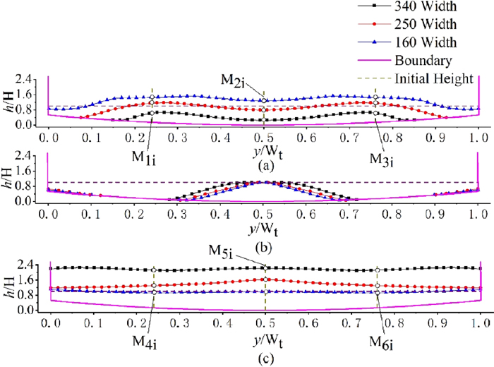
A cross-sectional view of the bottom dross morphology ((a) close to the front wall, (b) through the sink roll axis, (c) close to the back wall). (Online version in color.)

A longitudinal section view of bottom dross morphology ((a) close to the end face of the sink roll, (b) the symmetry plane along the x axis). (Online version in color.)
Figure 6(a) exhibits profiles of bottom dross morphology in a section which is parallel to front wall and 60 mm apart. A common feature of bottom dross morphology for different strip widths is the three carters in accumulation region A. With the decreasing of strip width, the intensity of FIF decreases. As a result, the middle pit becomes shallow in depth and the other two pits with bare bottom become narrow in width. Moreover, with the intensity of SIF increasing, the thickness of bottom dross deposition increases. The flow direction of molten zinc and the deposition direction of scattered bottom dross are determined by the competition mechanism between FIF and SIF in intensity. From the comparison between three monitoring parameters and initial height, the intensity relation between FIF and SIF can be deduced. In the case of strip width 340 mm, three monitoring points are significantly lower than the initial height, which indicates that the intensity of FIF is greater than SIF and the scattered bottom drosses are carried by the MCF to deposit towards back wall. However, in the case of strip width 160 mm, three monitoring points are significantly higher than the initial height, meaning that the intensity of FIF is lower than SIF. Consequently, the molten zinc moves in two opposite directions at the bottom of pot and more and more scattered bottom drosses are deposited towards front wall. In the case of strip width 250 mm, the magnitude of monitoring points is approach to the initial height. FIF and SIF are substantially equal to each other in intensity. In this condition, the number of scattered bottom drosses is the lowest.
A cross-sectional view of bottom dross morphology in the plane, which is parallel to front wall and passes through sink roll axis, is shown in Fig. 6(b). As can be seen from the figure, with the width of strip decreasing, the primary outlines of ridges located in accumulation region B becomes narrow. However, for different strip widths, the summit of deposited bottom dross approaches the same value of 95 mm. This illustrates the independence between the height of morphology and strip width in accumulation region B.
A graph of bottom dross morphology in a plane which is parallel to the back wall and 60 mm apart is provided in Fig. 6(c). Because the transport ability of MCF is weaken, thickness of bottom dross deposition decreases with the width of strip decreasing. The combination of the three monitoring parameters can be utilized to estimate transport ability of MCF for different strip widths. In the case of strip width 160 mm, thickness of bottom dross deposition is almost coincided with the initial height. It suggests that bottom dross rise up and scatter towards the front of the zinc pot before reaching the back wall, which leads to few bottom drosses deposit in this region.
Figure 7(a) exhibits profiles of bottom dross morphology in a longitudinal section situated in the region where there is no strip winded around the surface of sink roll and the distance from the longitudinal section to the side wall of the bath is 176 mm. Monitoring points M1i and M4i are located in this plane. The figure reveals that a crater with no dross on the bottom stays in accumulation region B. With the width of strip decreasing, the intensity of SIF increases, which causes the crater to move towards the front wall and the height of monitoring points M1i to increase. With the width of strip increasing, the intensity of FIF increases, which enhance the transport ability of MCF. The summit of deposited bottom drosses gradually comes near to the back wall and the height of monitoring points M4i increases.
Figure 7(b) displays a view of bottom dross morphology in the symmetry plane along the y axis. M2i and M5i are situated in this symmetry plane. The figure also points that the height of monitoring points M2i decreases and the summit of deposited bottom dross comes near to the back wall as well as an increase in its height with the increasing of strip width. The height of the ridge in accumulation region B keeps almost the same height, indicating that the feature is independent of the width of strip. At this point, it agrees well with the results of Fig. 6(b).
The basic researches for deposition pattern and morphology formation mechanism of bottom dross are essential to develop a new control technology of bottom dross. The effects of variable production parameters on the molten zinc flow field and dynamic deposition behaviors of bottom dross are investigated by the water model and numerical simulation, respectively. The main conclusions are summarized as follows:
(1) Two impact flows and the main circulation flow can be observed in the zinc pot, and the interactions among them determine the dynamic deposition behaviors of bottom dross. The first impact flow rushes slantingly downwards and disperses bottom dross in accumulation region A. Three impact craters with symmetric distribution along the front wall have taken shape. The second impact flow sprays along the tangential direction of the sink roll surface on bottom drosses in accumulation region B, leading to the formation of two symmetric pits with a ridge between them. The main circulation flow transports the scattered bottom dross along the bottom of the zinc pot towards accumulation region C.
(2) The width of strip has a significant effect on the deposition directon of bottom dross. With the width of strip decreasing, the intensity of the first impact flow decreases while the intensity of the second impact flow increases, resulting in the deposition direction of bottom dross changing from backward to backward as well as forward. As the effects of the first impact flow and the second impact flow are balanced against each other, stir-up of the bottom dross is suppressed at the bottom of the zinc pot, which can decrease the chance of dross particles touching the strip surface. It is beneficial for the strip to avoid adhering dross to the surface.
(3) With the speed of strip decreasing, the flow pattern is not altered, but the intensity of flow field is lowered. Meanwhile, the number of scattered bottom dross in the flow region is significantly reduced.
(4) The scattered bottom dross deposit towards forward or backward in the zinc pot, which has an important significance for achieving harmless accumulation of bottom dross. The results of this study provide theoretical basis and experimental design for control technology of bottom dross. Besides, in view of the influence of temperature fluctuation on bottom dross deposition, circulating pumps will be employed in the water model to simulate the heat flow produced by inductors in follow-up studies.
This work was supported by the National Natural Science Foundation of China (Grant No. 11672072, 11172063) and the Fundamental Research Funds for the Central Universities of China (Grant No. N2005009). This support is gratefully acknowledged.
D: Particle diameter
Fr: Froude number
g: Acceleration due to gravity
L: Characteristic length
Re: Reynolds number
V: Velocity
λ: Scale factor
ρ: Density
μ: Kinematic viscosity
Subscriptsm: Model
p: Prototype
inc: Inclusion
f: Fluid