Abstract
Owing to the heat transfer from high-temperature liquid steel, the temperature of the coil in the electromagnetic induction controlled automated steel teeming (EICAST) system in the ladle is very high, seriously restricting the service life of the coil. A novel air-mist cooling method was adopted to reduce the coil temperature in this paper. Firstly, the air-mist generating device was optimized. The results reveal that the optimized air-mist generating device can improve the cooling effect dramatically. And then, the influence of water flow and gas flow on the cooling effect of the coil was analyzed. Both water flow and gas flow affect the final coil temperature and the cooling rate of the coil. The final coil temperature is seen to decrease with an increase in the water flow, and the cooling rate of the coil increases at the initial stage. When the gas flow increases, the final coil temperature does not change much, but the cooling rate of the coil is uncommonly promoted. Finally, a combined cooling method based on the thermal cycle process of the ladle was proposed. After this method, the final coil temperature is 255°C. Compared with air-mist cooling, the final temperature difference is not large, but the coil temperature is kept in a low level for a long time by using the combined cooling. These studies will promote the application of the EICAST technology which can reduce non-metallic inclusions in steels.
1. Introduction
Steel cleanliness is an important indicator to ensure the steel quality, which largely determines the performance of final products.1,2) Drainage sand, as a non-metallic inclusions in steels, enters the tundish with liquid steel and leads to serious steel pollution during the continuous casting production process.3) Moreover, the widely used sliding gate technology prevents the self-opening rate of ladle from reaching 100%. When the self-opening is not possible, oxygen burning operation is often required, which not only increases steel pollution, but also affects the production rhythm and increases labor intensity.4,5) As a new technology applied to the teeming process of the ladle, the electromagnetic induction controlled automated steel teeming (EICAST) system has received much attention.6) Drainage sand is replaced by Fe–C alloy particles with the same or similar composition as liquid steel.7) Temperature gradient of Fe–C alloy is formed by the heat transfer from high temperature liquid steel. Before steel teeming, the formed Fe–C alloy blocking layer is melted by the coil encapsulated inside the nozzle brick.8) While eliminating the use of the drainage sand completely, EICAST system can also make the self-opening rate reach 100%.9)
The induction coil is the core component of the EICAST system. When the system works, the Fe–C alloy blocking layer in the upper nozzle is heated and melt entirely or partly by the coil, thereby completing the steel teeming process under the static pressure of liquid steel.10) Because the upper surface of the nozzle brick is in direct contact with high-temperature liquid steel, the ambient temperature of the coil is very high.11) If no measure is taken to reduce the coil temperature, the coil service life cannot meet the actual requirements of on-site production. Li et al. analyzed the temperature change of the coil after installing thermal insulation materials around the coil by numerical simulation method, and determined the best thermal insulation scheme through experiments.12) Although the heat insulation can reduce the coil temperature, the temperature reduction is limited.
During induction heating process, in order to ensure the service life of induction coil and improve production efficiency, cooling is an effective method to reduce coil temperature.13,14) So, it is necessary to select a cooling method to further reduce the coil temperature in EICAST system. The cooling effect of air cooling is poor due to the small cooling rate and short cooling time. Since the coil is installed at the bottom of the ladle, there is a potential safety hazard for water cooling. In industrial production, air-mist cooling is a common technique, which uses the phase change of water to absorb heat and achieve the purpose of cooling, having good cooling effectiveness.15,16,17)
Therefore, we attempt to reduce the coil temperature by means of the air-mist cooling. When the water content is small enough, the water has completely vaporized before moving to the highest position of the coil, which can eliminate potential safety hazard. To further ensure the safety of the EICAST system, a temperature sensor is installed on the top side of the coil. The cooling device will be turned off as soon as the coil temperature is abnormal. In this paper, after the optimized design of the structure of the air-mist generating device, the influence water flow and gas flow on the cooling effect of the coil were investigated, respectively. Combined with the thermal cycle of the ladle in industrial production, a combined cooling method was proposed and its cooling effect was analyzed.
2. Experimental Device and Process
An air-mist cooling experimental device shown in Fig. 1 was established to investigate and analyze the effect of the air-mist cooling for the induction coil in the EICAST system. The main structural parameters in the experimental device are shown in Table 1. The upper surface of the nozzle brick was heated by a high-temperature resistance furnace with the maximum temperature of 1600°C to simulate the heat brought by the liquid steel. The induction coil was installed inside the nozzle brick, and the distance between the upper side of the coil and the top surface of the nozzle brick was 150 mm. A thermocouple was installed on the upper side of the coil, monitoring the temperature change of the coil constantly. The air-mist generating device was installed at the inlet of the coil and connected with the gas and water pipelines. At the outlet of the air-mist generating device, the water in the cooling pipe was broken into small water droplets by high pressure gas using a mechanical method, and entered the high-temperature coil together with the gas.
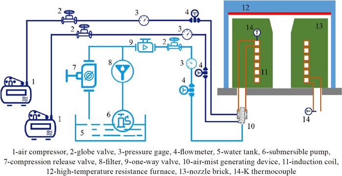
Table 1. Main structural parameters in the experimental device.
| Items | Values |
|---|
| Copper coil height | 150 mm |
| Section size of the coil | 20×20 mm |
| Wall thickness of the coil | 3 mm |
| Inner diameter of the coil | 235 mm |
| Outer diameter of the coil | 275 mm |
| Distance between the upper side of the coil and the top surface of the nozzle brick | 150 mm |
| Nozzle brick height | 350 mm |
The specific experimental steps were as follows:
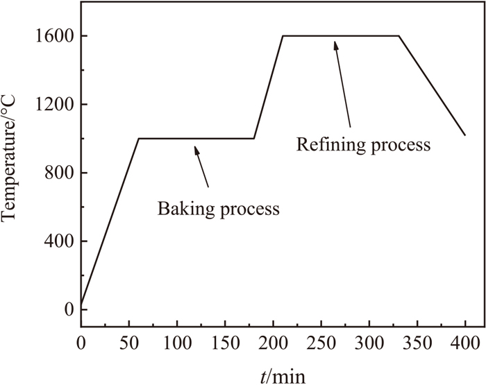
(1) According to the heating program set in advance, the high-temperature resistance furnace was used to heat the upper surface of the nozzle brick, the heating curve was shown in Fig. 2.
(2) When the coil temperature reached the initial condition of the air-mist cooling, the gas and water pipelines were opened. At the same time, the gas flow and water flow were adjusted according to the experimental parameters shown in Table 2. When the water flow was 0 L/h, the auxiliary atomization gas pipeline and water pipeline were closed. The mainstream gas pipeline was opened, and the gas flow was adjusted according to the parameter setting.
Table 2. Parameter design in the cooling experiments.
| Parameter | Unit | Value |
|---|
| Gas flow | L/min | 70, 100, 130, 160, 190 |
| Water flow | L/h | 0, 5, 10, 15 |
(3) The auxiliary high pressure gas atomized the water at the outlet of the air-mist generating device, then the air-mist mixture underwent a special improved mainstream gas channel, and the mainstream gas and the air-mist mixture were mixed.
(4) Air-mist mixture carrying water droplets was heat-exchanged in the coil to reduce the temperature of the tube wall, achieving the purpose of coil cooling.
(5) The thermocouple arranged around the coil inside the nozzle brick was connected to the data acquisition system, the coil temperature value was recorded every 10 s.
3. Results and Discussion
3.1. Optimized Design of the Air-mist Generating Device
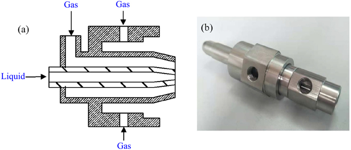
The object of traditional air-mist cooling is usually the flat or large-sized workpiece, and the spray cone angle is large.18,19) During atomization, the number and total surface area of atomized droplets increase. The friction between the droplet and the ambient gas will weaken the kinetic energy of atomized droplets. Penetration distance, an important parameter in the spray process, is limited.20) When the initial pressure is constant, the penetration distance decreases with the increase of the spray cone angle.21) So traditional air-mist generating device cannot be directly used for cooling the spiral coil. Before using the air-mist method to cool the coil, the structure of the air-mist generating device needs to be optimized. The optimized structure of the air-mist generating device is shown in Fig. 3. Atomization method using the additional gas flow can promote the effective atomization.22) So, an annular gas channel is added around the traditional air-mist nozzle in this paper. The high-pressure gas from the annular channel can weaken the collision between the air-mist mixture and the tube wall of the coil, thereby reducing the spray cone angle of the air-mist mixture. In addition, it also contributes to raising the kinetic energy of the droplets.
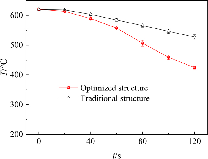
Cooling effects of the optimized and traditional structures of the air-mist generating device are compared and analyzed in experiments. When the water flow is 6 L/h and the air flow is 90 L/min, the temperature change of the coil during the cooling process of 2 min is shown in Fig. 4. When using the traditional structure, it is obvious that water seeps from the coil entrance. The atomized droplets collide with the inner wall of the coil and gather. the condensed water adheres to the inner wall, hindering the movement of the newly generated droplets and causing backflow. After the cooling, the coil temperature decreases by 93°C. When using the optimized structure, the phenomenon of water droplet aggregation and backflow is improved obviously. The coil temperature decreases by 196°C at the end of cooling.
The above results show that adding annular gas channel between the nozzle and the inner wall of the coil can significantly improve the movement state of the air-mist mixture inside the coil. Their basic principles are shown in Fig. 5. For the traditional air-mist generating device, under the action of gas pressure, the water droplets formed by breaking will drive the surrounding air to move together and form the atomization angle.23) As shown in Fig. 5(a), the air-mist mixture will collide with the coil wall in the flow process. Coil temperature at this position is usually low, so the small water droplets will collide and condense on the wall surface, forming backflow. There are two main reasons for this phenomenon. One is that the kinetic energy and pressure potential energy of atomization medium are consumed during the liquid atomization process. These energy losses are contributed to overcome the surface tension hindering the increase of liquid surface area, the viscous dissipation restraining liquid deformation and the mechanical energy consumed in the flow process.24,25) The other is that the air-mist mixture with high speed will drive the ambient air to move together.26) A negative pressure zone is formed between the air-mist generating device and the tube wall of the coil.
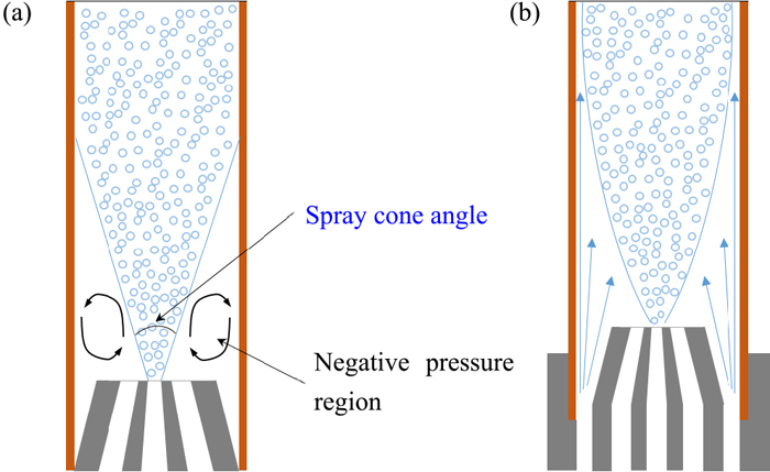
As shown in Fig. 5(b), by adding an annular gas channel around the air-mist generating device, the negative pressure area caused by the entrainment of the air-mist mixture to the surrounding air can be eliminated, and a boundary layer of gas flow is formed at the inner wall of the coil. The water droplets deviate from the moving direction and avoid accumulation and backflow without colliding with the tube wall. Therefore, the optimized structure of the air-mist generating device can improve the cooling effect of the coil effectively.
3.2. Influences of Different Parameters on the Cooling Effect of the Coil
The reason why the air-mist cooling effect is superior to the air cooling effect is that the broken water droplets will flow with the high pressure gas in the coil tube.27) When the coil temperature is high enough, the liquid droplets will undergo a phase change, absorbing a lot of heat. Therefore, the water flow in the air-mist mixture has a great influence on the cooling effect of the coil. At the same time, the gas flow is positively correlated with the gas flow velocity, and the movement of water droplets is achieved by the gas flow. Thus, the gas flow directly affects the movement velocity of water droplets, thereby affecting the cooling effect. Therefore, the influence of the water flow and gas flow on the cooling effect of the coil is analyzed in this paper.
3.2.1. Influence of the Water Flow on the Cooling Effect
Latent heat of evaporation is the key parameter that affects the enhancement of heat transfer in air-mist cooling.28) The water content in the air-mist mixture affects the total heat absorption of phase change evaporation. It is very essential to analyze the influence of water flow on coil cooling effect. When the gas flow is constant, the influence of the water flow on the coil temperature is shown in Fig. 6. When the gas flow rates are 70, 100, 130 and 160 L/min, the temperature changes of the coil at different water flow rates are shown in Figs. 6(a), 6(b), 6(c) and 6(d), respectively. Some error bars are significantly large in figures. The reason for these errors is that the air compressor producing high pressure gas is unstable because of large gas flow. But they will not affect the experimental results and the analysis of cooling trend. Obviously, the effect of air-mist cooling is significantly better than the effect of air cooling (water flow = 0 L/h). The increase of the water droplets’ mass fraction intensifies the heat transfer substantially. The main reason of the heat transfer intensification is the latent heat of water droplets evaporation.29) From Fig. 6(d), when the cooling time is 120 s and the gas flow is 160 L/min, the water flow increases from 0 to 5 L/h, and the final coil temperature decreases from 419°C to 294°C. As the water flow continues to increase, the cooling effect of the coil will continue to increase, but the increase is very limited. The results show that the water droplets move fast and cannot be fully evaporated when the gas flow is large. Especially at the end of cooling, the coil temperature has been significantly reduced. At this point, water droplets cannot be completely evaporated to produce phase transitions. Water droplets without evaporation have little effect on heat transfer.29) When the spray density increases, coil surface temperature does not fully recover before another water droplet impact to a same point.30) This also reveals that too much water flow cannot significantly reduce the coil temperature in the air-mist cooling process.
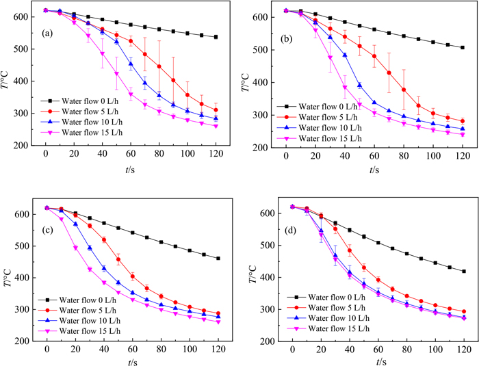
It is worth noting that in the initial stage of cooling, as the water flow increases, the decrease rate of coil temperature increases. Taking Fig. 6(b) as an example, when the water flow is 5 L/h, it consumes 120 s to reduce the coil temperature from 620°C to 282°C. When the water flow rate is 15 L/h, the time for the coil temperature to decrease from 620°C to 282°C is 75 s. The experimental results fully prove that the cooling effect of air-mist cooling is better than that of air cooling in a short time. With the increase of water flow, the cooling rate is faster. Water droplets undergo phase transition and absorb large amounts of heat from the inner wall of the induction coil.31) If the cooling time of the coil needs to be shortened, an appropriate increase in water flow is an option.
3.2.2. Influence of the Gas Flow on the Cooling Effect
The gas flow affects the flow rate of the air-mist mixture in the coil, and then affects the phase transition and evaporation of water droplets. Therefore, it is necessary to investigate the cooling effect of the coil at different gas flow rates. When the water flow is constant, the influence of the gas flow on the temperature change of the coil is shown in Fig. 7. When the water flow rates are 0, 5, 10 and 15 L/h, the temperature changes of the coil at different gas flow rates are shown in Figs. 7(a), 7(b), 7(c) and 7(d), respectively. In Fig. 7(a), when the water flow is 0 L/h, as the gas flow rate increases, the air cooling effect gradually increases, and the decrease extent of the coil temperature increases firstly and then decreases. When the gas flow is greater than 160 L/min, the cooling effect is almost no longer enhanced. It can be seen from Figs. 7(b), 7(c) and 7(d) that when the water flow is constant, as the gas flow increases, the final coil temperature almost does not change. From the experimental results, the gas flow has little effect on the final coil temperature. It mainly plays the role of transporting water droplets.32)
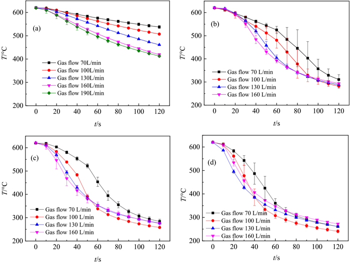
However, an increase of air flow will cause the coil temperature to decrease more quickly. The temperature distribution of the spiral coil is gradient from top to bottom in the EICAST system.11) At the initial stage of cooling, the high temperature at the top of the coil results in the phase transition of water droplets. In a short time, gas velocity increases, heat transfer coefficient also increases.30) Fast gas speed can transport a large number of water droplets to the top of the coil. So, the decrease rate of coil temperature significantly increases with the increase of gas flow. This is very meaningful for rapid cooling of the coil in industrial tests. Therefore, in the air-mist cooling process, the gas flow should be increased as much as possible within an allowed range.
3.3. Coil Temperature Change during the Combined Cooling
In the EICAST system, the coil temperature needs to be reduced to a certain value within a relatively short period of time. The reason why air cooling cannot meet the requirements is that its cooling effect is very limited in a short time. In the refining process of liquid steel, the ladle is static in the refining position, and the whole process lasts longer. Therefore, a combination of the air cooling in refining process and the air-mist cooling before steel teeming can be attempted. To this end, high-temperature experiments are conducted to investigate the temperature change of the coil during the combined cooling process.
Figure 8 shows the specific process of the combined cooling, the measurement method of coil temperature and the temperature change of coil in the whole cooling process. As shown in Fig. 8(a), When the upper surface temperature of the nozzle brick rises to 1600°C, that is, after the ladle reaches the refining position, the coil is air-cooled at a gas flow of 130 L/min. The refining process lasts for 2 h. After the refining phase is completed, a process conversion time of 10 min is required. When the ladle is moving, the coil cannot be cooled. After the ladle is placed at a ladle turret, the coil is cooled by air-mist method. The cooling time is 120 s, the gas flow is 100 L/min, and the water flow is 10 L/h.
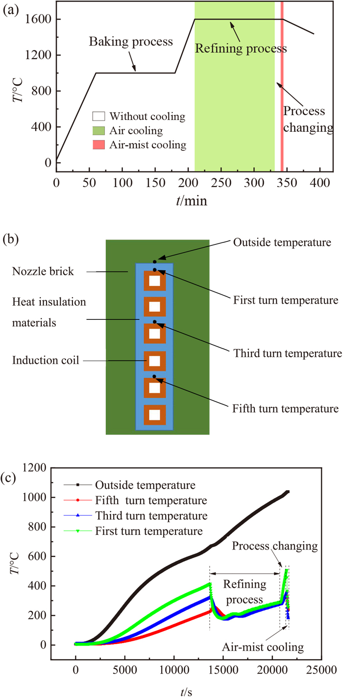
In order to analyze the temperature change of the coil accurately, 4 thermocouples are installed around the coil. The installation positions of thermocouples are shown in Fig. 8(b). The temperature changes of the coil during the whole process are shown in Fig. 8(c). The temperature outside the heat insulation materials (outside temperature) has been rising continuously throughout the whole process. In the initial stage of cooling, the heating rate decreases slightly. These reveal that cooling for the induction coil has little effect on the temperature outside the heat insulation materials. After a comparative analysis of the first turn temperature, the third turn temperature and the fifth turn temperature, two conclusions can be drawn. First, as the temperature measurement position moves downward, the time at which the coil temperature begins to decrease is delayed during cooling process. Second, the temperature on the upper side of the coil is always the highest. Therefore, the first turn temperature should be paid more attention in the research of coil service life. In the refining stage, when the air cooling starts, the temperature on the upper side of the coil (first turn temperature) is 415°C. As the cooling process continues, the coil temperature decreases to 182°C. After that, the coil temperature begins to rise slowly, indicating that the heat taken by the air cooling is less than that transferred by the liquid steel to the coil through the nozzle brick. At the end of the refining process, the temperature on the upper side of the coil is 292°C. During the transition process, the coil temperature rises sharply. This occurs when the cooling effect is not enough to reduce the temperature of other medias around the coil.33) At the beginning of the air-mist cooling, the coil temperature has risen to 507°C. After air-mist cooling of 120 s, the coil temperature drops to 255°C.
In summary, compared with the air-mist cooling before steel teeming, the coil temperature at the end of the combined cooling does not decrease significantly. However, during the whole process, the combined cooling can keep the coil at low temperature. This is favorable to ensure the service life of the coil. Therefore, in industrial applications, the combined cooling method should be selected.
4. Conclusions
To reduce the coil temperature, the structure of traditional air-mist generating device is optimized, and the effects of different parameters on the coil temperature in the air-mist cooling system are analyzed, a combined cooling method based on the ladle thermal cycle process is proposed finally. The main conclusions are as follows:
(1) Adding an annular gas path around the traditional air-mist generating device can reduce the atomization angle of the air-mist mixture, weaken the collision between the air-mist mixture and the tube wall of the coil, and improve the cooling effect.
(2) Compared with the effect of air cooling, the effect of air-mist cooling is greatly improved. During the air-mist cooling process, water flow and gas flow both affect the cooling effect and the cooling rate of the coil. When the gas flow is constant, increasing the water flow will decrease the final coil temperature, and increase the decrease rate of the coil temperature at the initial stage of cooling. The water flow is constant, when the gas flow increases, the final coil temperature almost does not change, but the decrease rate of the coil temperature in the initial stage of cooling increases dramatically.
(3) Using the combined cooling, the coil is air-cooled in the refining stage, and it is air-mist-cooled before steel teeming. The final coil temperature is 255°C, does not change much, but the coil temperature can be kept within a relatively low level, which has a positive effect for ensuring the service life of the coil.
Acknowledgements
This research was financially supported by the National Natural Science Foundation of China (No. U1560207), the National Key R&D Program of China (No. 2017YFB0304402) and the Liaoning Innovative Research Team in University (No. LT2017011).
References
- 1) L. F. Zhang and B. G. Thomas: ISIJ Int., 43 (2003), 271.
- 2) K. Steneholm, N. A. I. Andersson, A. Tilliander and P. G. Jönsson: Ironmaking Steelmaking, 45 (2018), 114.
- 3) F. Farshidfar and M. Ghassemi Kakroudi: J. Iron Steel Res. Int., 19 (2012), 11.
- 4) Y. Kobayashi, H. Todoroki, F. Kirihara, W. Nishijima and H. Komatsubara: ISIJ Int., 54 (2014), 1823.
- 5) Z. Y. Deng, B. Glaser, M. A. Bombeck and D. Sichen: Steel Res. Int., 87 (2016), 921.
- 6) X. A. Liu, Q. Wang, D. J. Li, G. L. Li, D. Q. Geng, A. Gao and J. C. He: ISIJ Int., 54 (2014), 482.
- 7) Q. Wang, D. J. Li, X. A. Liu, X. B. Wang, J. Dong and J. C. He: J. Iron Steel Res. Int., 22 (2015), 30.
- 8) D. J. Li, Q. Wang, X. A. Liu, A. Gao, X. B. Wang, J. Dong, K. Marukawa and J. C. He: J. Iron Steel Res. Int., 19 (2012), 766.
- 9) A. Gao, D. J. Li, Q. Wang, K. Wang, B. G. Jin, K. Marukawa and J. C. He: ISIJ Int., 50 (2010), 1770.
- 10) M. He, X. L. Li, Z. Q. Cao, S. L. Dong, T. Liu and Q. Wang: Vacuum, 146 (2017), 130.
- 11) M. He, X. L. Li, X. A. Liu, X. W. Zhu, T. Liu and Q. Wang: Acta Metall. Sin. (Engl. Lett.), 32 (2019), 391.
- 12) X. L. Li, M. He, X. W. Zhu, Q. W. Wang and Q. Wang: Metals, 9 (2019), 434.
- 13) T. T. Tsung, C. H. Lo, C. S. Jwo, H. Chang and K. C. Wang: Int. J. Adv. Manuf. Technol., 29 (2006), 99.
- 14) H. Shokouhmand and S. Ghaffari: Appl. Math. Model., 36 (2012), 4304.
- 15) Y. Kikuchi, K. Tatsuta and M. Sako: J. Nucl. Sci. Technol., 35 (1998), 477.
- 16) M. Colombo, A. Cammi, G. R. Guédon, F. Inzoli and M. E. Ricotti: Prog. Nucl. Energy, 85 (2015), 462.
- 17) C. A. Hernández-Bocanegra, A. H. Castillejos E., F. A. Acosta-González, X. X. Zhou and B. G. Thomas: Exp. Therm. Fluid Sci., 44 (2013), 147.
- 18) I. Hernández C., F. A. Acosta G., A. H. Castillejos E. and J. I. Minchaca M.: Metall. Mater. Trans. B, 39 (2008), 746.
- 19) R. J. Issa: J. Therm. Sci., 19 (2010), 253.
- 20) L. M. Geng, Y. J. Wang, Y. Y. Wang and H. M. Li: J. Traffic Transp. Eng. (Engl. Ed.), 7 (2020), 331.
- 21) E. Martínez-Galván, R. Antón, J. C. Ramos and R. Khodabandeh: Exp. Thermal Fluid Sci., 50 (2013), 127.
- 22) M. Ochowiak and M. Matuszak: Eur. J. Pharm. Sci., 97 (2017), 99.
- 23) V. Novak, D. Sadowski, S. Shin, K. Schoonover and S. I. Abdel-Khalik: Fusion Sci. Technol., 47 (2005), 610.
- 24) A. Yu. Vasil’ev and A. I. Maiorova: High Temp., 52 (2014), 250.
- 25) G. W. Monk: J. Appl. Phys., 23 (1952), 288.
- 26) B. P. Husted: Proc. IWMA Conf., IWMA Conference, Rome, (2004), 1.
- 27) N. Gandhi and S. Suresh: J. Therm. Anal. Calorim., 141 (2020), 2231.
- 28) V. I. Terekhov, M. A. Pakhomov, K. A. Sharov and N. E. Shishkin: Int. J. Heat Mass Transf., 48 (2005), 1760.
- 29) M. A. Pakhomov and V. I. Terekhov: Flow Turbul. Combust., 98 (2017), 341.
- 30) N. Sozbir, Y. W. Chang and S. C. Yao: J. Heat Transf., 125 (2003), 70.
- 31) Y. Z. Zhang, Z. Wen, Z. W. Zhao, J. Huang, W. F. Wu and B. W. Li: ISIJ Int., 59 (2019), 1072.
- 32) Y. Ma, M. J. Zhang and H. S. Luo: Chem. Eng. Res. Des., 162 (2020), 173.
- 33) N. Sozbir and S. C. Yao: At. Sprays, 14 (2004), 191.