Abstract
The effect of 2CaO·SiO2 (C2S) addition on the melt formation temperatures and on the microstructures of iron ore sinters has been elucidated from the perspective of the formation of silico-ferrite of calcium and aluminum (SFCA) in bonding phases as SFCA phases improve the strength of iron ore sinter. The samples used in this study are categorized into two: “C + S” and “C2S”. “C + S” samples contain CaO and SiO2 as CaO and SiO2 components, while “C2S” samples contain intermediate compounds of CaO and SiO2, i.e., C2S. Both samples have an identical chemical composition. The mixed raw materials were subjected to differential thermal analysis (DTA) and sintering experiment. DTA reveals that the melt formation temperatures are 1182°C and 1216°C for the “C + S” and “C2S” samples, respectively, which are sufficiently lower than the normal sintering temperatures. Sintering experiment reveals that the larger amount of SFCA exist in the “C + S” sample than in the “C2S” sample. This may be associated with the fact that some SiO2 gangue minerals and reagents remain unreacted for the “C + S” sample, causing the CaO/SiO2 ratio of the slag melt to be larger for the “C + S” sample than for the “C2S” sample.
1. Introduction
Iron ore sinters are the main iron source of the current blast furnace ironmaking process in Asia. Iron ore sinters are agglomerates connected by bonding phases or “necks”, which are formed by the melt reaction of limestone with iron ore particles.1,2,3) Because steel-making slags contain calcium compounds such as CaO, CaCO3, Ca(OH)2 and 2CaO·SiO2 (C2S),4,5) the slags are often reused as a raw material for sinters by a replacement for limestone.6,7) However, it has been known that the sinters produced by the addition of steel-making slags has lower strength rather than the sinters produced from limestone.7) The strengths of sinters depends on the amount of melt produced during sintering, the melt formation temperature, and the chemical compositions and the microstructures of sinters.8) With respect to the amount of melt, the sinter strength becomes higher as the amount of melt is larger. Thus, the decrement in the sinter strength caused by the addition of steel-making slags may stem from that the CaO component required to form the slag melt is insufficient in steel-making slags. Kumasaka et al.6) have examined the degradation of sinter strength caused by the addition of steel-making slags from the perspective of the melt formation temperature. They have reported that the temperature at which the melt forms between steel-making slag and Fe2O3 (1350°C) is much higher than that between limestone and Fe2O3 (1270°C) and have suggested that C2S in the slag raises the melt formation temperature. In contrast, Hoshi and Kawaguchi7) have reported that the melt formation temperature and the fluidity of melts are independent of compounds of raw materials, but only depend on the chemical compositions of sinters.
The microstructure of sinters is also a factor affecting the sinter strength. Oyama et al.8) have reported that the strength of sinters can be described by the strength of bonding phase, the porosity and the pore size distribution, and that the strength of bonding phase increases with an increase in the fraction of SFCA. Among these factors affecting the sinter strength, we have focused on the formation of SFCA. To the best of authors’ knowledge, there has been little discussion on the effect of C2S on the formation of SFCA so far.9) Thus, the aim of this study is to elucidate the effect of C2S addition on the melt formation temperatures and on the microstructures of sinters from the perspective of the formation of SFCA in bonding phases.
2. Experimental
2.1. Samples
Table 1 shows the chemical composition of the samples, which has been determined by targeting the sinter chemical composition. The samples are categorized into two: “C + S” and “C2S” samples. The raw materials of “C + S” samples were mixtures of Brazilian hematite, burnt lime obtained by firing limestone and SiO2, Al2O3 and MgO reagents. Table 2 shows chemical compositions of Brazilian hematite and limestone. The reason that Brazilian hematite has been used in this study is that it contains less SiO2 and Al2O3 so as to evaluate the effect of C2S addition on the reaction behavior more clearly. For the “C2S” samples, SiO2 and a part of CaO were substituted by C2S. Table 3 shows the mixing ratios of raw materials for “C + S” and the “C2S” samples. Brazilian hematite was crushed using alumina mortar and pestle and sieved into powders with the particle size of 75–90 μm. Burnt lime was obtained by firing limestone at 1000°C for more than 12 h in air, and subsequently ground and sieved into powders with the particle size of 38–75 μm. C2S was synthesized from reagent CaCO3 and SiO2 powders as follows: Powder mixtures of CaCO3 and SiO2 (CaCO3/SiO2 = 2 in molar ratio) were uniaxially pressed to form a tablet. The tablet was placed onto a Pt crucible and heated in air at 1300°C for 48 h. Then, the tablet was crushed into powders, pressed to form a tablet and heated again in the same manner. It was confirmed by X-ray diffraction (XRD) analysis that the sample has the single phase of C2S after the heat treatment was repeated twice. Pulverized C2S was also passed through a sieve to obtain a powdery sample having the particle size of 38–75 μm. SiO2, Al2O3 and MgO reagents were also passed through a sieve to obtain powdery samples with a particle size smaller than 38 μm. The mixed raw materials were subjected to differential thermal analysis (DTA) and sintering experiment.
Table 1. Chemical compositions of the samples (mass%).
| T.Fe* | CaO | SiO2 | Al2O3 | MgO | C/S |
|---|
| “C + S”/“C2S” Samples | 57.39 | 10.03 | 5.09 | 1.91 | 0.48 | 1.97 |
Table 2. Chemical compositions of Brazilian hematite and limestone (mass%).
| T.Fe | CaO | SiO2 | Al2O3 | MgO | LOI |
|---|
| Brazilian hematite | 65.80 | 0.04 | 1.51 | 1.22 | 0.05 | 2.6 |
| Limestone | 0.09 | 54.90 | 0.49 | 0.16 | 0.51 | 43.85 |
Table 3. Mixing ratios (mass%) of raw materials for “C + S” and “C
2S” samples.
| “C + S” | “C2S” |
|---|
| Brazilian hematite | 85.26 | 85.28 |
| Burnt lime | 10.00 | 3.00 |
| C2S | – | 10.50 |
| SiO2 reagent | 3.60 | – |
| Al2O3 reagent | 0.80 | 0.82 |
| MgO reagent | 0.34 | 0.40 |
DTA was applied to the mixed raw materials to investigate how the substitution of C2S for an equivalent quantity of CaO and SiO2 affects the melt-formation temperatures. About 30±5 mg of mixed powders was placed in an Al2O3 crucible with 4.6 mm in diameter and 4.5 mm in height and subjected to DTA. The reference material was α-Al2O3. DTA measurements were carried out at a constant heating rate of 15°C/min up to 1300°C in air. The measurement temperature was calibrated using Ag, Au and Ni melting points as references. To confirm that the observed endothermic peaks correspond to the melting of the samples, the samples were heated up to the temperatures below and above the temperatures of endothermic peaks in the same manner as DTA analyses, kept at the temperatures for 5 min, and then cooled at a constant cooling rate of 75°C/min to room temperature, which is the possible largest cooling rate of the DTA furnace. The microstructures of the obtained samples were observed by electron probe microanalyzer (EPMA).
To elucidate the effect of substitution of C2S for an equivalent quantity of CaO and SiO2 on the microstructures of the sintered samples, the mixed raw materials were heated as follows: About 450 mg of raw materials were uniaxially pressed by a compaction pressure of 40 MPa for 30 s to form tablets with 10 mm in diameter and ca. 2 mm in thickness. A tablet was put on a Pt crucible, and the crucible with a tablet was inserted into an electric furnace maintained at 1300°C. In 5 min after the onset of heating, the crucible with a tablet was took out from the furnace and cooled by air cooling. The part of sintered samples was crushed into fine powders and was subjected to XRD analyses to identify major constituent phases. The microstructures of the sintered samples were observed by EPMA. The area percentages of Fe2O3, SFCA, slag and pores were calculated by image analysis software ImageJ for BE images. 10 images were used for each sample, which were taken at randomly chosen positions covering all the sections. The area percentage of pores may be dependent on the condition of uniaxial compaction of powders before sintering. Thus, the difference in the microstructures of bonding phases between the “C + S” and the “C2S” samples has only been focused in this study.
3. Results and Discussion
3.1. Melt-formation Temperatures of Raw Materials
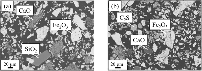
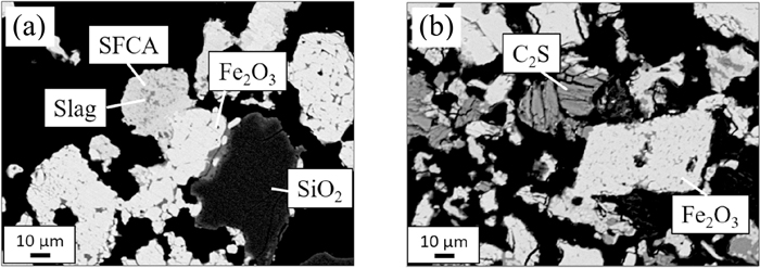
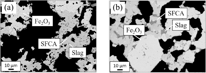
Figure 1 shows the DTA curves over the temperature range from 1170°C to 1230°C. The DTA curves reveal that the temperatures of endothermic peaks are 1182°C and 1216°C for “C + S” and “C2S” samples, respectively. Thus, the samples were heated up to 1172°C, 1186°C and 1217°C and subjected to the microstructure observations to confirm that the endothermic peaks correspond to the melting of the samples. Figures 2, 3, 4 show backscattering electron (BE) images of “C + S” (a) and “C2S” (b) samples heated up to 1172°C, 1186°C and 1217°C, respectively. In BE images, the brighter area corresponds to the larger average atomic number of that area relative to adjacent areas. It can be seen from Fig. 2 that unreacted raw materials remain for both samples heated up to 1172°C, which demonstrates that the melting does not take place at 1172°C regardless of the addition of C2S to the raw materials. The inspection of Fig. 3 indicates that the melting does not occur on the “C2S” sample, but, SFCA is precipitated from the melt on the “C + S” sample at 1186°C. At 1217°C, SFCA phases are generated from the melts on both samples, as shown in Fig. 4. Thus, it is concluded that the endothermic peaks at 1182°C and 1216°C correspond to the melting of the “C + S” and the “C2S” samples, respectively. The substitution of C2S for an equivalent quantity of CaO and SiO2 results in an increment in melt formation temperature by ca. 30°C, which may be due to that C2S is rather thermodynamically stable among intermediate compounds of CaO and SiO2.10,11) The normal sintering temperature is sufficiently higher than the melt formation temperatures of both samples. However, temperature distribution is not uniform in the sintering bed. The maximum temperature at upper part of sintering bed is known to be lower than middle and bottom part. In the light of un-uniformity of temperature, the difference in the melt formation temperature below 1200°C may give lower assimilation rate, leading to the difference in the volume and composition of sinter melt, then sinter structure.
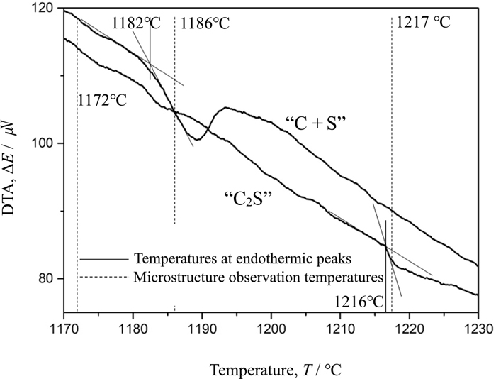
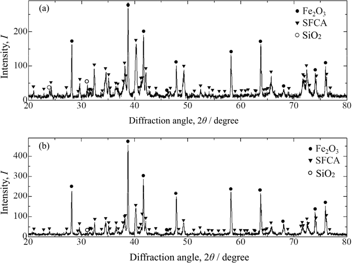
Figure 5 shows XRD profiles for “C + S” (a) and “C2S” (b) samples sintered at 1300°C in the 2θ ranges of 20°–80°. Both samples have the diffraction peaks due to Fe2O3 (PDF database No. 01-073-2234), SFCA (PDF database No. 00-046-0037) and SiO2 (PDF database No. 01-085-0035). The diffraction peaks due to SiO2 for “C2S” sample stem from gangue minerals contained in ores.
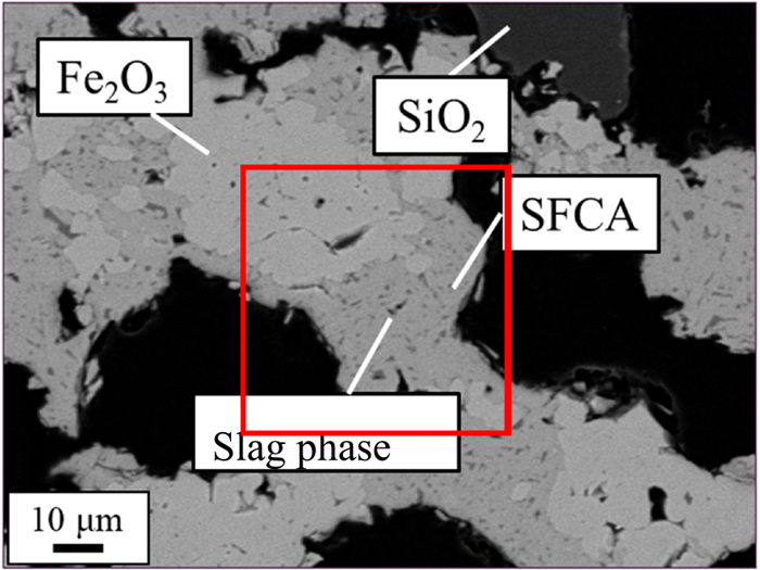
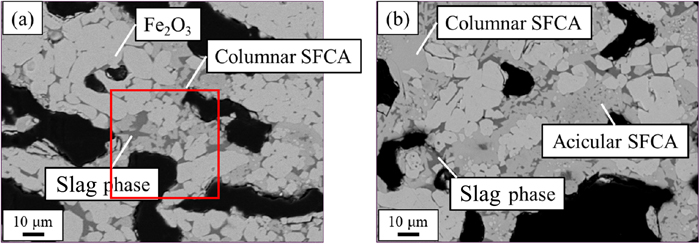
Figure 6 shows a typical BE image of the “C + S” sample sintered at 1300°C, where Fe2O3, acicular SFCA, slag and residual SiO2 are observed. Figure 7 shows two typical BE images of the “C2S” sample sintered at 1300°C, i.e., (a) Fe2O3, columnar SFCA and slag, and (b) Fe2O3, columnar SFCA, acicular SFCA and slag although, in fact, acicular SFCA can hardly be observed in the “C2S” sample. Here, acicular and columnar SFCA phases are defined by those having the width smaller and larger than 10 μm, respectively. C2S was not observed both in the “C + S” and “C2S” samples.
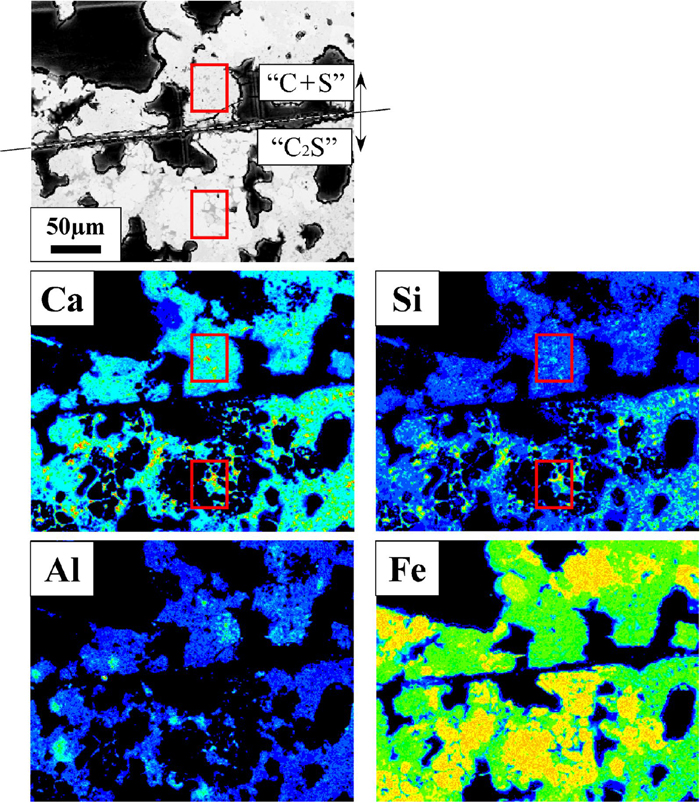
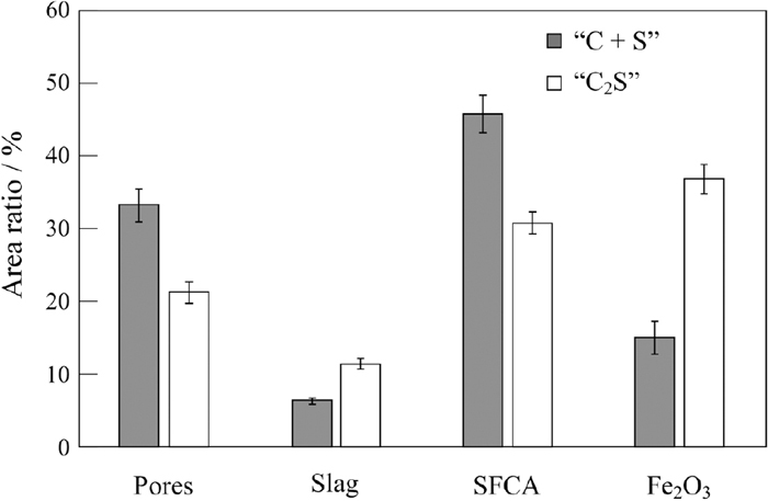
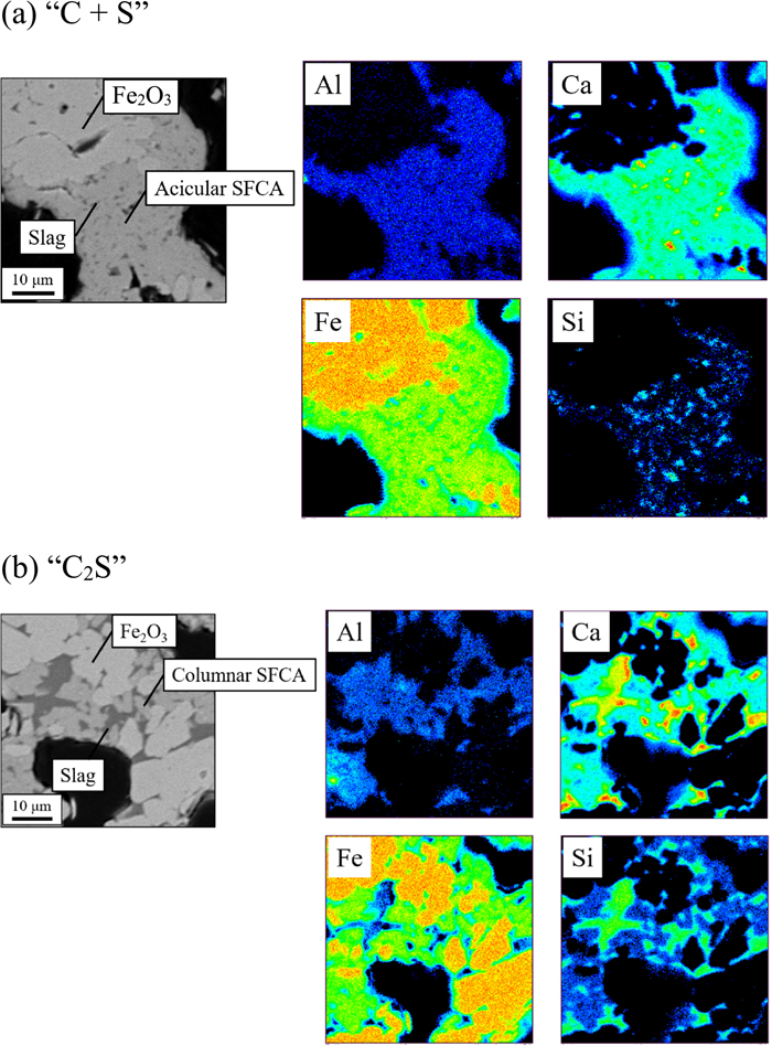
Figures 8(a) and 8(b) show BE images and element mapping images of Al, Ca, Fe and Si for the square areas for Figs. 6 (“C + S”) and 7 (“C2S”), which include acicular and columnar SFCA phases, respectively. For both samples, Al exists in SFCA and in some slag phases, and can hardly be observed in Fe2O3. Ca and Si also exist in SFCA and slag, and Si is particularly concentrated in the slag phase. In order to compare the CaO/SiO2 ratio of slag phases, the “C + S” and “C2S” samples were embedded alongside each other in the same resin. Figure 9 shows a BE image and element mapping images of Al, Ca, Fe and Si for the “C + S” and “C2S” samples. It can be found that the CaO/SiO2 ratio of slag phase in the “C + S” sample is larger than that in the “C2S” sample; the red rectangular areas enclose slag or C2S phases for the “C + S” and “C2S” samples, Ca and Si images of which are more brightly colored compared to the surroundings. However, Si image for “C + S” is less bright compared to that for “C2S”. Thus, the CaO/SiO2 ratio of the slag melt is larger for the “C + S” sample than for the “C2S” sample. In fact, inspections of Figs. 3(a) and 6 reveal that some SiO2 gangue minerals and reagents remain unreacted for “C + S” samples. These results may be explained as follows: the initial melt is formed by the reaction between CaO and Fe2O3. SiO2 can hardly assimilate with the initial melt although C2S can assimilate with the initial melt. This explanation is also supported by Fig. 5 in addition to Figs. 3(a) and 6. Inspection of Fig. 5 reveals that the intensity ratio of the diffraction peak due to SiO2 to that due to Fe2O3 is larger for the “C + S” sample than that for the “C2S” sample in spite of the fact that both samples have the same composition. This implies that more SiO2 remained undissolved in the “C + S” sample sintered at 1300°C, resulting in that SiO2 can hardly assimilate with the initial melt. In this study, SiO2 was added into the samples as reagents as well as gangue minerals contained in ores. In practical cases, SiO2 may exist in raw materials of sinters as various minerals such as quartz and kaolinite. The particle sizes and the distributions of SiO2 in sintering bed may also range widely, which result in various sintering properties.12) The relation between the existence form of SiO2 and its fluxing capability will be studied in the future. Figure 10 shows area percentages of Fe2O3, SFCA, slag and pores for “C + S” and “C2S” samples. The error bar represents the standard deviation. With the addition of C2S, area percentages of SFCA decrease and those of slag and Fe2O3 increase.
Inspection of Figs. 8, 9, 10 implies that the fraction of SFCA may be associated with the CaO/SiO2 ratio of slag contributing to the melt formation, which is larger for “C + S” samples than for “C2S” samples. The relation between the CaO/SiO2 ratio of slag and the SFCA formation will be discussed in the next section.
3.3. Mechanism of the Formation of SFCA Phase
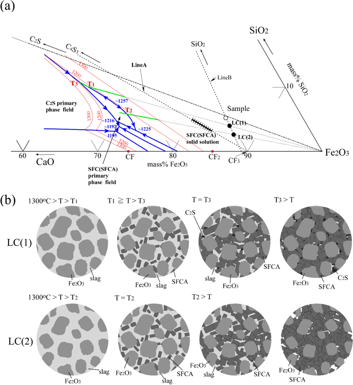
According to the phase diagram of the CaO–SiO2–Fe2O3-2 mass% Al2O3 at 1300°C in air,13) Fe2O3 and liquid phases are equilibrated for both samples. To the best of the authors’ knowledge, there is no available phase diagram of the CaO–SiO2–Fe2O3–Al2O3 system to explain the formation process of SFCA. Thus, the CaO–SiO2–Fe2O3 phase diagram reported by Chen et al.14) was used to interpret the formation of SFCA phases. Figure 11(a) shows phase equilibrium of the iron-rich corner of the CaO–SiO2–Fe2O3 system in air including liquidus, the SFC and C2S primary phase fields, the SFC solid solution and the sample composition of this study.14) The straight lines connecting 4CaO·3SiO2 (C4S3) and CaO·3Fe2O3 (CF3), and SiO2 and sample composition are denoted by Line A and Line B, respectively. SFC solid solution is on the Line A. T1 and T2 correspond to the temperatures at the intersections of the boundary between SFC (SFCA) and Fe2O3 primary phase fields with the extensions of straight lines connecting LC (1) and Fe2O3 and LC (2) and Fe2O3, respectively. T3 corresponds to the eutectic temperature of SFC (SFCA), Fe2O3 and C2S. If some SiO2 gangue minerals and/or reagents in raw materials remain unreacted during sintering, the local composition of the sample shifts away from SiO2 corner of the CaO–SiO2–Fe2O3 system along Line B. Now, assume that the local compositions of LC (1) and LC (2) in Fig. 11(a) correspond to the “C2S” and “C + S” samples, respectively, on the basis that the raw materials are ununiform and some SiO2 gangue minerals and reagents remain unreacted. Figure 11(b) shows schematic illustrations of the equilibrium microstructures for LC (1) and LC (2). For both compositions, Fe2O3 and liquid phases are equilibrated at 1300°C, and then during the cooling cycle, SFC (SFCA) phases are precipitated from liquid phase at T1 and T2 for LC (1) and LC (2), respectively. With respect to LC (1), when the temperature decreases to T3, C2S is precipitated from the residual liquid. On the other hand, as for LC (2), Fe2O3 and SFC (SFCA) phases are equilibrated below T2. Because Lines A and B approach each other as the CaO/SiO2 ratio is larger, the fraction of SFC (SFCA) is larger for LC (2) than that for LC (1). Consequently, it has been found that the larger amount of SFCA exists in the “C + S” sample than in the “C2S” sample. However, a part of the liquid became glassy without precipitation of C2S because the cooling rate of the samples was not slow enough to attain the equilibrium.
4. Conclusions
(1) DTA reveals that the melt formation temperatures are 1182°C and 1216°C for “C + S” and “C2S” samples, respectively, which is sufficiently lower than the normal sintering temperatures. The present result is consistent with the previous report that the melt formation temperature between steel-making slag and Fe2O3 is higher than that between limestone and Fe2O3.6)
(2) Sintering experiment reveals that the larger amount of SFCA exist in the “C + S” sample than in the “C2S” sample. This may be associated with the fact that some SiO2 gangue minerals and reagents remain unreacted for the “C + S” sample, causing the CaO/SiO2 ratio of the slag melt to be larger for the “C + S” sample than for the “C2S” sample.
References
- 1) M. Sasaki and Y. Hida: Tetsu-to-Hagané, 68 (1982), 563 (in Japanese). https://doi.org/10.2355/tetsutohagane1955.68.6_563
- 2) N. Webster, M. I. Pownceby, I. Madsen and J. Kimpton: Metall. Mater. Trans. B, 43 (2012), 1344. https://doi.org/10.1007/s11663-012-9740-5
- 3) S. Nicol, J. Chen, M. I. Pownceby and N. A. S. Webster: ISIJ Int., 58 (2018), 2157. https://doi.org/10.2355/isijinternational.ISIJINT-2018-203
- 4) L. Holappa and O. Wijk: Treatise on Process Metallurgy, Vol. 3, Industrial Processes, ed. by S. Seetharaman, Elsevier, Oxford, (2014), 354.
- 5) Y. Chen, M. Ko, J. Chang and C. Lin: Constr. Build. Mater., 158 (2018), 132. https://doi.org/10.1155/2018/4150145
- 6) A. Kumasaka, K. Kondo, N. Sakamoto, H. Noda and M. Shimizu: CAMP-ISIJ, 4 (1991), 1051 (in Japanese).
- 7) M. Hoshi and S. Kawaguchi: CAMP-ISIJ, 7 (1994), 137 (in Japanese).
- 8) N. Oyama, K. Nushiro, Y. Konishi, K. Igawa and K. Sorimachi: Tetsu-to-Hagané, 82 (1996), 719 (in Japanese). https://doi.org/10.2355/tetsutohagane1955.82.9_719
- 9) T. R. C. Patrick and R. R. Lovel: ISIJ Int., 41 (2001), 128. https://doi.org/10.2355/isijinternational.41.128
- 10) F. D. Richardson: Physical Chemistry of Melts in Metallurgy, Vol. 1, Academic Press, London, (1974), 256.
- 11) S. Sato, T. Kawaguchi, M. Ichidate and M. Yoshinaga: Tetsu-to-Hagané, 70 (1984), 657 (in Japanese). https://doi.org/10.2355/tetsutohagane1955.70.7_657
- 12) T. Miki and Y. Fujita: ISIJ Int., 55 (2015), 1206. https://doi.org/10.2355/isijinternational.55.1206
- 13) C. K. Yang, T. Shoji and S. Takenouchi: J. Min. Metall. Inst. Jpn., 94 (1978), 575. https://doi.org/10.2473/shigentosozai1953.94.1087_575
- 14) J. Chen, M. Shevchenko, P. C. Hayes and E. Jak: ISIJ Int., 59 (2019), 795. https://doi.org/10.2355/isijinternational.ISIJINT-2018-575