Lymphatic Imaging
The lymphatic system is made up of the lymphatic organs (lymph nodes, spleen, thymus, tonsils, and appendix) and the vessels (lymph capillaries, precollectors, collectors, trunks, and thoracic ducts). When the lymphatic pathway is impaired, lymphatic leakage may cause lymphoceles, chylothorax, or chylous ascites, and a lymphatic obstruction can result in lymphedema in the extremities. Consequently, lymphatic imaging is indicated to obtain anatomical information for accurate diagnosis and treatment planning. Particularly for lymphedema, the advent of new microsurgical approaches, such as lymphaticovenular anastomoses (LVAs) to bypass the excess fluid component by joining with the circulatory system peripherally, in addition to conventional conservative therapies, has underscored the importance of lymphatic imaging. For the correct evaluation of the function and pathways of impaired lymphatics, various imaging modalities can detect lymphatic flow, which is often masked beneath the dermal backflow (DBF) caused by the accumulation of lymph in either the skin or subcutaneous tissues.16,17 In healthy individuals, the “linear pattern” of lymphatic channels can be seen (Fig. 1A). However, the DBF observed in lymphedema patients often obscures the lymphatic vessel pathways toward the proximal regions (Fig. 1D).

Because direct lymphangiography, which requires a skin incision for the insertion of a catheter into a lymphatic vessel, is so invasive,19,20 indirect lymphography with an intradermal or subcutaneous injection of contrast agent is currently the most often used method of lymphatic imaging. Representative imaging modalities include lymphoscintigraphy,21 magnetic resonance lymphography (MRL),22,23,24 and indocyanine green (ICG) near-infrared fluorescence (NIRF) lymphography (Fig. 1A,D).5,6,25,26 Additionally, non-contrast MRL27,28 and high-resolution ultrasound (US) imaging29,30,31,32 have been introduced as new techniques without the need for contrast agent injection, which can cause adverse reactions in some patients. Inevitably, all these imaging modalities are based on different principles; consequently, every option has specific advantages and disadvantages.19 Moreover, these imaging approaches lack standardized procedures even within centers that specialize in lymphatic disorders, resulting in variable results.33 Furthermore, none of these methods can visualize the anatomical architecture of the small veins around the peripheral lymphatics19 or the actual flow of lymphatic transport within a lymphatic vessel, both of which have long been unmet needs in the field of lymphatic surgery to achieve more successful LVA.
Unlike previous techniques, PAI has a high spatial resolution with an acoustic depth of penetration. The spatial resolution of PAI varies from the submicrometer range at submillimeter imaging depths to the submillimeter range at depths up to several centimeters.34 Over these ranges, PAI provides detailed images of the superficial blood vessels containing hemoglobin. Using an exogenous contrast agent such as ICG, lymphatic vessels can also be visualized clearly. The unique characteristics of PAI can therefore improve the quality of research in this field.
Photoacoustic Imaging
PAI is based on the photoacoustic (PA) effect, first described by Alexander Graham Bell in 1880,35 which occurs when light illuminates tissues. When a tissue is illuminated with short-pulse non-ionizing light, absorption of the optical energy by local molecules causes the local temperature to increase, resulting in transient thermoelastic expansion. This expansion generates localized pressure waves (ultrasound) that can be detected using ultrasonic transducers to generate an image.36 Representative light-absorbing biomolecules include oxy- and deoxyhemoglobin, lipids, water, and melanin. These are endogenous chromophores, and each exhibits its own characteristic absorption spectrum. For example, in the detection of PA waves from hemoglobin illuminated by near-infrared (NIR) light, blood vessels can be visualized without using exogenous contrast agents.37,38,39,40,41,42,43,44,45,46 By utilizing multiple wavelengths of illumination, PAI can differentiate arteries from veins by assessing the oxygen saturation of the blood thanks to the difference in the absorption profiles of oxyhemoglobin and deoxyhemoglobin.7,37,47,48 In addition to the spectral unmixing of chromophores, the unique scalability of the spatial resolution and depth penetration resulting from the combination of light and sound with PAI also highlights important advantages over conventional imaging techniques. Therefore, PAI provides not only structural but also functional information from molecules in real-time at clinically relevant depths with a relatively high spatial resolution and without the use of ionizing radiation.7 Moreover, because the transducers can be arranged in two dimensions (2D) or three dimensions (3D), either a 2D cross-sectional image or a 3D volumetric image can be reconstructed. Utilizing the information provided by PAI, many clinical applications have been demonstrated recently.47 Although PAI is still an emerging technology, a few commercial PAI systems have already been approved for clinical use by regulatory authorities in the European Union.47 In addition to commercialized clinical and preclinical systems, most of which are equipped with handheld PA probes,8,9,49,50 many different PAI-platforms, including laboratory prototypes, also exist. PA microscopy, intravascular PAI via catheters, PA endoscopy, and PA tomography (PAT) with a stationary examination bed unit are some examples. The wide range of preclinical and clinical applications using these systems has been reviewed elsewhere.7,36,47,51
Recently, a prototype PAT system with a wide field of view (WF-PAT) has been developed by a Japanese research group (Fig. 2).38 This system has metamorphosed through several versions37,39,40,41 to acquire PA signals from a maximal field of view (FOV) of 270 × 180 mm2 in 10 min with a resolution of approximately 0.2 mm.38 Using this type of system, various clinical studies have been performed. Observation of the peritumoral and intratumoral vasculature, the response to chemotherapy,41 the investigation of potential biomarkers42 related to breast cancer, the evaluation and preoperative mapping of the 3D vasculature of the thigh for free flap reconstruction surgery,43,44 and analysis of the findings in digital or palmar arteries related to motion,45 aging,46 or inflammatory disease (psoriasis)48 have shown encouraging results.
Photoacoustic Lymphangiography
PAL is a new imaging technique that is being investigated clinically to visualize the lymphatic vessels using PAI technology.8,9,10,11,12,13,14,15 Because lymphatic fluid is transparent, the lymphatic vessels lack endogenous chromophores to absorb light in the NIR wavelength range, with which a deeper penetration of light is achieved due to its lowest total absorbance in the background tissue components. As a result, exogenous imaging agents such as ICG8,9,10,11,12,13,14,15 or methylene blue49,52 have been used to facilitate imaging. This approach enables PAL not only to visualize both lymphatic vessels and small veins simultaneously but also to spectroscopically distinguish between them using the difference in absorption spectra between the dye taken up by the lymphatics and the hemoglobin in the veins.12 This feature allows visual differentiation of lymphatics from blood vessels using color to help operators distinguish them.8,9,10,11,12,13,14,15,52 This is an important advantage over traditional medical imaging modalities that give each coordinate a single value and therefore produce only monochromic images, often leading to the lymphatic vessels being misidentified as small veins. PAL can also provide real-time imaging of the lymphatic vessels, which is useful for direct observation of the lymphatic pumps.8,10,11 The pumps involve spontaneous smooth muscle contraction of the collecting lymph vessels53 to generate a flow of lymphatic fluids, which may reflect each vessel’s capacity for lymph transport.54
Two kinds of preclinical commercial devices with handheld probes have been used to identify the lymphatic vessels in a healthy person9 and in lymphedema patients.8 However, the FOV was so limited that lymphatic and vascular mapping over a large area of the limbs was not possible. In contrast, PAL using the WF-PAT system38 (WF-PAL) revealed previously unknown 3D structural information over a large area in both healthy and lymphedematous extremities.10,11,12,13,14,15
Lymphatic vessels in healthy people
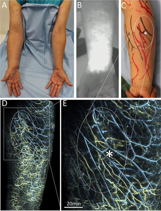
In PAL, ICG is so frequently used as a contrast agent that NIRF lymphography is often undertaken at the same time.8,12,13 Because ICG contains trace amounts of iodine, administration to subjects with previously known iodine reactivity should be avoided. Whereas NIRF shows the typical linear courses of lymphatic vessels under healthy conditions, the deeper lymphatic vessels become blurred with this technique (Fig. 1A). WF-PAL, however, visualizes the corresponding lymphatic vessels more clearly compared to those visualized by NIRF, in 3D (Fig. 1A, B).12 Furthermore, the superficial venous network around the lymphatics, which may not be visualized by NIRF, can also be depicted (Fig. 1C).12
The WF-PAT system can perform imaging in still mode, in which a large area can be imaged by scanning with a hemispherical US detector array, as utilized for WF-PAL. Additionally, the system can operate in video mode, in which a specific site with a FOV of 20 mm in diameter can be irradiated with laser light to repeatedly obtain updated PA images of the same site,25 thereby potentially enabling real-time visualization of the lymphatic pumps10,11 (Fig. 3; a supplementary video is also available). The lymphatic pumps observed using this function occurred intermittently at various intervals, and the velocity of the lymphatic flow also varied from subject to subject. However, there was a tendency for the flow in the upper limbs to be faster than that in the lower limbs.10
Abnormal lymphatic vessels in lymphedema patients
In lymphedema patients (e.g., as shown in Fig. 4A), particularly those with a distinct DBF on lymphoscintigraphy14 or NIRF12 (Fig. 1D, 4B), WF-PAL can reveal the complex 3D structures of the DBF in high resolution10,11,12,14,15 (Fig. 1E, 4D). Visualization of the lymphatics that generate a DBF had never been achieved at such a resolution before the development of WF-PAL.14 In a previous study using computed tomography–lymphography (CT-LG), which showed the 3D architecture of a DBF,17 the small lymphatic vessels branching upward from the deep lymphatic collectors toward the dermis were visualized. However, the complex 3D structure of the DBF itself, as shown with WF-PAL, was not possible due to limited sensitivity20 and resolution. The smallest lymphatic vessels identified by CT-LG and PAL were 0.717 and 0.28,11 mm in diameter, respectively. On the other hand, other 3D imaging modalities, including MRL22,23,24 and single photon emission CT (SPECT-CT),55 depict DBFs as a blurred area on the skin, which limits the visualization of the lymphatic vessels inside the DBF itself.
PAL also showed that there were many collecting vessels underneath the DBF and many of these seemed to be twisted (Fig. 4E), which may reflect the lymphatic overload and increased internal pressure. A previous histochemical study revealed that as lymphedema progresses, the lumen of lymphatic vessels become dilated, then narrowed, and then finally obstructed.56 If the morphological features of the lymphatic vessels visualized noninvasively by PAL follow this process, then progression of the pathological changes of each vessel may be predicted, which will be very useful for selecting target lymphatic vessels for LVA.
Advantages for clinical applications toward the better management of lymphedema
Whereas other imaging modalities such as lymphoscintigraphy and NIRF lymphography are unable to visualize the lymphatic vessels underneath a DBF,21 PAL has successfully identified not only the lymphatic vessels, but also the small veins underneath a DBF8,11 (Fig. 4E). Contrast-enhanced MRL also obtains full-thickness 3D information on the lymphatic vessels and soft tissue in a DBF23; however, it does not provide information on the relationship between the lymphatics and small veins. Recently, conventional high-frequency US (CHFUS) with an upper frequency of 15–24 MHz29,30,31 and ultrahigh-frequency US (UHFUS) with an upper frequency of 70 MHz32 were used to visualize the lymphatic vessels underneath a DBF as seen by NIRF. However, these imaging procedures can be difficult for less experienced operators, in part because the monochromic 2D image makes it challenging to distinguish lymphatic vessels from small veins or nerves. In PAL, the lymphatic and blood vessels can be differentiated by color8,10,11,12,13,14,15,52(Fig. 1C,F; 3A-C; 4D,E), rendering the images easier to interpret even for individuals without medical knowledge.
Another advantage of WF-PAL is that it generates information on the precise structure of small veins. Although veins are an important counterpart to lymphatic vessels for a successful LVA,57 there has never been a tool for mapping superficial veins at the submillimeter scale.58 Because PAL can clearly visualize vessels as small as 0.2 mm in diameter8,11 in superficial regions up to 20 mm in depth,14 the resultant morphology of the vasculatures is similar to that marked on the patient as part of the planning of LVA surgery using conventional methods such as NIRF for the lymphatics and CHFUS for the small veins (Fig. 4C,E). Whereas the conventional procedures for this study took more than 60 min for mapping by an experienced examiner (SH) using NIRF and CHFUS, WF-PAL took approximately 15 min to acquire each image.12
Additionally, although the feasibility of PAL for LVA surgery has already been indicated by comparing the vessel position based on PAL with the intraoperative surgical microscopic view,8 WF-PAL also provides information on the 3D relationship between the lymphatic and venous pathways over a wide area, which was not previously acquired using other imaging techniques. Therefore, WF-PAL enables improved LVA planning with the choice of better target veins to increase the drainage of lymph into the local venous circulation by taking into account the 3D relationship between the lymphatic vessels and the functional perforating veins to achieve more effective lymphatic drainage.
Moreover, the outstanding features of PAL allow postoperative assessment of anastomoses because PAL provides a clear image to visualize both the lymphatic vessels and the veins. No conventional modality has succeeded in imaging the anastomosis itself. Although evaluation of the postoperative patency rate is an important outcome of LVA surgery, there is no ideal method to assess the patency of LVAs in the clinical setting.59 In two clinical studies that used NIRF to assess patency,25,26 no more than half of the anastomoses could be assessed because of depth limitations. In contrast, PAL can clearly visualize vessels in superficial regions up to 20 mm deep8,14 and those above the deep fascia.12Therefore, it should be possible to visualize the anastomoses directly because LVA is usually achieved between vessels in the superficial layers.29,30,31,57
Limitations and future directions
PAI is still an emerging technology currently under development, and, in addition to the major advantages mentioned above, there are still some important challenges to overcome.7,47 First, given the limitations of light penetration, PAI may result in poor image quality in areas with thicker subcutaneous tissues,7 which are often found in lymphedema patients. Also, the spatial resolution will be high at higher US frequencies, but with lower depth penetration as a trade-off because of the increasing attenuation of ultrasound with increasing frequency.7,36 This is similar to the finding that the deepest layer from which UHFUS can obtain images is 10 mm from the superficial surface.33 Furthermore, the difficulty in detecting vessels deeper than the deep fascia,12,15,43 which cannot be explained using the principles above, may be due to acoustic heterogeneity.60 The differences in sound velocity in tissues such as subcutaneous tissues, deep fascia, and subfascial tissues can hinder the reconstruction of a clear image from the intensity of the PA signals. Therefore, the implementation of compensation algorithms to correct for the distribution of sound velocities in different tissues61 as part of the image reconstruction process may improve the image quality.
Second, the signal intensity generated by hair shafts is stronger than that of blood vessels or ICG-filled lymphatic vessels; the reason for this is that melanin provides great contrast for PAI in the NIR wavelength range often used for vascular imaging.7 Even if hairs are removed using hair clippers before an examination, residual hair roots can interfere with analysis of the images.8,38 The application of depilatory creams to completely remove the hair shaft in advance may be an option; however, implementation of a body surface detection algorithm62 may help to remove the hair volume data and facilitate the analysis of deeper structures.
Regarding WF-PAT, in addition to the common limitations noted above, this modality cannot obtain structural information other than that from the targeted chromophores in tissues such as the dermis, fat, superficial and deep facias, vessel walls, or nerves. However, such additional tissues could be visualized by systems that integrate PA and US imaging.50 Information on vessel wall thickness may be important for understanding the pathophysiological state of lymphedema31,56 or atherosclerotic diseases.7
Another limitation is a limited FOV. Although WF-PAT has a relatively large FOV among PAI devices, its configuration with a shallow holding tray38 limits the body regions that can be imaged. Because lymphatic surgeons need to know the lymphatic pathways throughout the limbs to assess and plan surgery for lymphedema, the use of PAL in combination with other imaging modalities, including lymphoscintigraphy, MRL, or NIRF lymphography, may be necessary to make accurate decisions and achieve good clinical outcomes.
Currently, the best potential application of PAL is for planning LVA procedures; however, the identification of target vessels in clinical practice can be difficult. Although the accuracy of lymphatic and venous mapping using WF-PAL imaging has not been clinically assessed, it may be important to carefully reproduce the patient’s positioning between the imaging examination and surgery. Vascular mapping technology on the body using projection mapping44,63 or augmented reality64,65 may also be useful for the preoperative preparation of LVA surgeries.
Nevertheless, as this rapidly progressing technology improves further, the current limitations may be overcome, paving the way for the clinical use of PAL, which it is hoped will contribute to improved treatment for lymphedema patients.


