Abstract
Multi-Walled Carbon Nanotubes (MWCNTs) have promising properties that make them potentially useful in a wide variety of applications. The decoration of MWCNTs by metallic or semiconducting nanoparticles aims to intensify some of their properties, in particular thermal and electrical conductivity. Fluidized Bed Chemical Vapour Deposition (FBCVD) is an efficient process to uniformly coat powders by various materials. The coating by SnO2, Fe and Si nanoparticles of MWCNTs (Graphistrength®) tangled in balls of 360 microns in mean diameter using the FBCVD process has been studied. The influence of some deposition parameters with and without oxidative pre-treatment is analysed on the nucleation and growth of nanoparticles. The various results obtained indicate that the intrinsic surface reactivity of MWCNTs is high enough for CVD precursors involving the formation of highly reactive unsaturated species such as silylene SiH2 formed from silane SiH4 pyrolysis in the case of Si deposition. But it must be enhanced for less reactive CVD precursors such as tin tetrachloride SnCl4 which needs the presence of oxygen-containing groups at the nanotube surface to allow Sn nucleation. So, provided the reactivity of the powder surface and that of the CVD precursors are well tuned, the FBCVD process can uniformly coat the outer surface of MWCNTs by metallic or semiconducting nanoparticles.
1. Introduction
Multi-Walled Carbon Nanotubes (MWCNTs) are nowadays a popular nanoform of graphenic carbon in which graphenes are arranged more or less parallel to the nanofilament axis. They have promising properties that make them potentially useful in a wide variety of applications such as electronics, renewable energy and composite materials. They exhibit a large surface area, high mechanical strength, and unique electrical properties, and are efficient thermal conductors (Monthioux et al., 2007). The decoration of MWCNTs by semiconducting or metallic nanoparticles (NPs) aims to intensify some of their physical properties. For instance, the deposition of silicon NPs on MWCNT networks allows the formation of anodes of Li-ion batteries with improved electrochemical performance due to the high specific capacity of silicon and good mechanical strength and structural flexibility of MWCNTs (Cui et al., 2010). Composites made of SnO2 NPs deposited on MWCNTs present excellent sensing responses for gas detection at room temperature (Mendoza et al., 2014). Metal-coated MWCNTs can be used as reinforcing and conductive fillers for high-performance polymer composites by combining the electrical conductivity of the metal and the mechanical properties of the nanotubes (Babal et al., 2014).
There are many methods of depositing nanoparticles onto MWCNTs, each offering various degrees of control of particle size and distribution along the MWCNTs (Wildgoose et al., 2006; Bacsa and Serp, 2012). They are generally classified in two groups: the wet methods including the electrochemical, sol-gel and impregnation methods, and the gas processes such as Physical Vapour Deposition (PVD), Atomic Layer Deposition (ALD) and Chemical Vapour Deposition (CVD) (Kuang et al., 2006; Bacsa and Serp, 2012; Goulas et al., 2014). The wet impregnation method is the most widely used technique even if a multi-step method, because of its simplicity (Bacsa and Serp, 2012). However, the size of the coated particles is difficult to control precisely (Kuang et al., 2006). The gas processes yield products purer than the wet methods. They are single-step methods and generally involve high coating rates (Bacsa and Serp, 2012). CVD on MWCNTs has often been used to deposit metallic (Pt, Pd, Ru, Rh) or semiconducting (InP, CdSe) nanoparticles (Bacsa and Serp, 2012), but most often at the milligram scale, on nanotubes either deposited or supported on a planar substrate or put into a crucible as a fixed powder bed.
CVD can be adapted to the large-scale production of coated MWCNTs provided a good gas-solids contact can be achieved. Gas-solids fluidisation consists in flowing a gas upwards through a vertical bed of particles, thus generating an intense gas-solids mixing and subsequently high thermal and mass transfer rates between the gas and the powders (Kunii and Levenspiel, 1991). Fluidisation can be combined with the CVD technology, giving rise to the Fluidized Bed Chemical Vapour Deposition (FBCVD) process. If the MWCNTs can be fluidized, this technology allows multi-gram-scale beds of nanotubes to be uniformly coated with a high conversion rate of the gaseous precursor into solids, high versatility, good homogeneity of products and the possibility of continuous operations (Vahlas et al., 2006). This technology is also easy to use and to rescale, and requires low equipment costs (Vahlas et al., 2006).
Whatever the process used, a bottleneck in the coating of MWCNTs by metallic or semiconducting materials often concerns their surface reactivity. Nanotubes are formed of graphenes often arranged in a concentric manner with both ends ideally capped by fullerene-like structures. Due to the seamless arrangement of hexagon rings without any dangling bonds, carbon nanotube walls are rather unreactive (Lin et al., 2003). Experimental observations have clearly shown that surface defects which are inherently present play an important role in the adsorption of atoms on MWCNTs. But as the density in defects is generally low, a surface activation in the form of functionalization or creation of defects at the carbon nanotube surface is essential to achieve a high coating density (Feng and Puddephatt, 2007; Bacsa and Serp, 2012). The most common method at the lab scale is the oxidative acid reflux that purifies and functionalizes the nanotubes in one step by grafting hydroxyl (C-OH), carbonyl (C = O) and carboxyl (O = C-OH) groups on the nanotube surface (Bacsa and Serp, 2012; Vennerberg et al., 2014). However, the liquid wastes generated by these wet oxidation methods are not suited to industrial use (Kim and Min, 2010). Some works about gas-phase oxidation of CNTs using either air (Ajayan et al., 1993; Behler et al., 2006) or nitric acid vapours (Xia et al., 2009; Li et al., 2012; Rong et al., 2010) at high temperatures have led to mixed results: the CNTs were structurally damaged or far worse, even partially burnt. Gas-phase oxidation from ozone (O3) is an environmentally friendly and low-cost route to form oxygen-containing groups on the CNT surface, even for mass production (Vennerberg et al., 2014). This route will be tested in the present work. By a pre-deposition of a titanium carbide (TiC) layer by CVD acting as a surface functionalization, Feng and Puddephatt (2007) have successfully increased the surface coverage of CNTs by Ni, Pd and Pt films deposited by CVD.
The present article aims to detail some examples of MWCNT coating by FBCVD in order to provide new insights concerning the interaction between a reactive gaseous phase leading to nanoparticle deposition and the nanotube surface. Three deposits were selected involving CVD precursors of very different reactivity and decomposition pathways. Tin oxide deposition from tin tetrachloride SnCl4 and water vapour will be first presented, and then silicon deposition from silane SiH4, and finally iron deposition from ferrocene Fe(C5H5)2. In particular, it will be shown that surface activation is not always necessary to coat MWCNTs by metallic or semiconducting particles.
2. Experimental set-up
The experimental set-up (Fig. 1) is composed of a vertical stainless steel FBCVD reactor (internal diameter of 8.3 cm and 1 m in height) heated by a two-zone external furnace. The top of the reactor is water-cooled to ensure gas tightness. A high-performance HEPA13 filtration cartridge is placed at the exhaust of the reactor to collect any elutriated particles.

At the bottom, a perforated steel plate provides a homogeneous gas distribution and the conical zone of the gas inlet is pre-heated by either an oil bath or heating ribbons. A differential pressure sensor (Unik5000; Druck Ltd.) with taps under the distributor and at the top of the reactor measures the pressure drop across the MWCNT bed. An absolute pressure sensor (PR21; Keller) allows monitoring the total pressure below the distributor. Temperature is measured by several K-type thermocouples: three in a small tube along the vertical axis of the reactor to check the MWCNT bed isothermicity (T1 at 6 cm above the distributor, T2 at 21 cm and T3 at 28 cm for the SnO2 and Si depositions, T1 at 6 cm, T2 at 12 cm and T3 at 21 cm for the Fe deposition), two on the outer reactor walls to control the temperature furnace and one in the bubblers when used.
Ferrocene Fe(C5H5)2 (98 %, Strem Chemicals) and tin chloride SnCl4 (anhydrous, 98 %, Strem Chemicals) are used as received. Deionised water is mixed to SnCl4 to deposit SnO2. Each is loaded into a specific bubbler placed in a thermostatically controlled oil bath and connected to the reactor entrance by thermostated controlled gas lines. The bath temperature is fixed at 50 °C for SnCl4 and H2O and at 155 °C for ferrocene. All the gas lines are heated by heating ribbons to the same temperature as the precursor bubblers to avoid any premature condensation. Gas flows (N50 N2 and H2, Air Liquide) are regulated by mass flow controllers (MFC-7700 type; Aera), except silane (Electronic grade SiH4, Air Liquide) whose flow rate is regulated by a ball rotameter (GT1355, Brooks Instrument). The ozone generator (Lab2B, Ozonia) is connected to the bottom of the FBCVD reactor and is fed with oxygen (Alphagaz oxygen, Air Liquide), ensuring an ozone concentration of 10 g.h–1. All the experiments are performed at atmospheric pressure.
Multi-walled carbon nanotubes (Graphistrength® C100; Arkema) were used without any purification treatment. As can be seen in Fig. 2a and 2b, they are entangled in the form of coarsely spherical balls of 388 μm in Sauter diameter.

Nanotube walls are made of 10–15 concentric graphenes with a mean external diameter of 12 nm. Some amorphous carbon is present on the walls and internal defects are visible (Fig. 2c). Their intrinsic iron content is 1.35 wt%. Their skeleton density is 1.984 kg/m3, whereas the grain density of the MWCNT balls was estimated at ∼180 kg/m3 and their untapped density is equal to 90 kg/m3 (Coppey, 2013) As found by other authors in the case of nanotubes (Yu et al., 2006; Dasgupta et al., 2011), these MWCNT balls display very good fluidization performance. They exhibit agglomerate particulate fluidization (APF) characteristics between 0 and 3.3 Umf (minimum fluidization velocity) and agglomerate bubbling fluidization (ABF) features beyond 3.3 Umf with high bed expansion (Coppey, 2013). This behaviour is characteristic of the fluidization of nanoparticle agglomerates (Zhu et al., 2005; Wang et al., 2007). It should favour excellent gas-solid contact and then high conversion rate of the CVD precursors and also uniform deposition. The minimum fluidization velocity Umf of the MWCNT balls measured at ambient temperature under N2 is equal to 1.2 cm.s–1 (Coppey, 2013).
MWCNTs were analysed before and after ozone pre-treatment and CVD by several characterization techniques. The powder morphology was observed by Field Emission Gun Scanning Electron Microscopy (FEG-SEM) on a Jeol JSM-7100F linked to an Energy Dispersive X-ray (EDX) detector (X-MAXN Oxford Instrument) and High-Resolution Transmission Electron Microscopy (HRTEM) using a CM30 (Philips) with LaB6 gun and operated at 150 kV to minimise damaging irradiation effects. The SEM and TEM images presented in the article were selected from many as the most representative ones of each sample. X-ray Diffraction (XRD) results were obtained using a D8-2 (Drucker) with a monochromatic Kα copper (Cu) source (λ = 1.5418 Å). The iron weight percentage deposited on MWCNTs was measured by ICP-MS (XSeries2 Thermo Scientific).
A dimensionless bed pressure drop ΔP* was calculated as the ratio between the bed pressure drop and the theoretical one (the latter being equal to the bed weight per unit section area). The bed pressure drop was obtained by subtracting the pressure drop of the distributor from the differential pressure measured.
The operating conditions tested are detailed in Table 1. 100 g of MWCNTs were used for each experiment, corresponding to a ratio between the fixed bed height and the reactor diameter of 2.3. Such a ratio is necessary to ensure good thermal transfer between the reactor walls and the FB and isothermal bed conditions, which are both well-suited to thermal CVD. The fluidization ratio U/Umf was fixed to 4 to ensure a good compromise between the gas-particle mixing and the residence time of the gas in the bed. For liquid and solid precursors, the gaseous precursor molar fractions entering into the reactor were estimated by assuming the equilibrium in the bubblers and using the vapour pressure laws of Yaws (1999) for SnCl4 and of Emel’yanenko et al. (2007) for ferrocene.
Table 1
Operating conditions tested and experimental results obtained
| Run |
Substrate |
Target deposit |
Average bed temperature (°C) |
Run duration (min) |
Precursor and inlet molar % |
Deposited mass deduced from bed weighing (g) |
Conversion rate of the main precursor (%) |
| T02 |
Raw CNTs |
SnO2 |
500 |
90 |
SnCl4—0.9
H2O—1.8 |
27 |
78 |
| T05 |
Raw CNTs |
SnO2 |
550 |
125 |
SnCl4—0.5
H2O—1.9 |
17 |
90 |
| T06 |
H2O-CNTs |
SnO2 |
550 |
120 |
SnCl4—0.5
H2O—1.9 |
15 |
79 |
| S30 |
Raw CNTs |
Si |
500 |
60 |
SiH4—7 |
40 |
100 |
| W6 |
H2O-CNTs |
Si |
500 |
60 |
SiH4—7 |
38.6 |
100 |
| nCNT3 |
Raw CNTs |
Fe |
650 |
180 |
Fe(C5H5)2—2.3 |
57 |
87 |
| nCNT9 |
O3-CNTs |
Fe |
650 |
180 |
Fe(C5H5)2—2.3 |
52.5 |
100 |
| nCNT10 |
O3-CNTs |
Fe |
550 |
180 |
Fe(C5H5)2—2.3 |
37.8 |
90 |
| nCNT13 |
Raw CNTs |
Fe |
650 |
180 |
Fe(C5H5)2—2.3 |
40 |
84 |
3. Results
3.1 Process behaviour
Fig. 3 presents the dimensionless bed pressure drop and thermal profile measured during run nCNT3. They are characteristic of the overall results obtained. The thermocouples T1 and T2 are located in the fluidized bed whereas T3 is just above the FB. Indeed, in a preliminary study conducted in a glass column, the fluidized bed height was measured at U/Umf = 4 as varying between 25 and 27 cm (Coppey, 2013).
This explains that the temperatures measured by T1 and T2 are very close to each other, thanks to the good gas-solids mixing and particle-wall contact existing in the fluidized bed. The bed thermal gradient did not exceed 5 °C for all the CVD experiments. The temperature measured by T3 is lower because the thermocouple is located in a region where the fluidized particles are more diluted in the gas and then it is directly in sight of the reactor walls.
The T1 and T2 temperatures were not adversely affected by the deposit, probably due to the quite low inlet molar fractions of the precursors tested. The T3 temperature decreases with run duration because the fluidized bed height tends to decrease due to the grain density increase induced by the deposit.
The dimensionless bed pressure drop ΔP* progressively increased during deposition, which is indicative of the good fluidization of the bed. This allows the increase of the bed weight due to deposition to be followed in real time. The agreement between the deposited masses deduced from the bed pressure drop and those obtained by weighing the bed before and after deposition is good on average, confirming that the bed of MWCNTs remained fluidized during the whole experiment.
The elutriation of the powder was low, on average less than 1 wt% of the bed after the CVD experiments. This is due to the fact that the MWCNT balls were not broken by the FBCVD treatment: the Sauter diameter of the powders after CVD remained very close to that before treatment, as measured by laser size scattering analysis (not shown).
3.2 SnO2 deposition
Possible CVD precursors of SnO2 are SnCl4, Sn(CH3)4, (CH3)2SnCl2 and SnH4 (VanMol, 2003; Coppey, 2013). By oxidation with O2 or hydrolysis with H2O, these precursors form a SnO2 layer. The most commonly used precursor is tin tetrachloride SnCl4 mixed with water, for which the deposition conditions are quite well established (Li and Hua, 1997; VanMol, 2003; Coppey, 2013). This route has been used here.
Fig. 4a presents SEM images of the MWCNT balls after run T02 was performed at 500 °C as detailed in Table 1. The deposit appears as micron-size particles at the ball surface, predominantly in the interstices and cracks within the balls. At higher magnification (Fig. 4b), some particles of the deposit can be distinguished. They present a pyramidal form, characteristic of crystalline materials. Their size ranges from a few hundred nanometres to several microns. The largest ones might be made up of aggregates of primary particles of the deposit. So, the surface coverage of the MWCNTs is low.

Some SEM-EDX analyses on MWCNT balls which had been opened along their hemisphere (Fig. 5) reveal that the SnO2 particles are present everywhere inside the balls. This means that the mass transfer rate inside the porous MWCNT balls is higher than or equal to the heterogeneous reaction rate, probably thanks to the quite low reactivity of the SnCl4 precursor on the nanotube walls. Table 2 summarizes the chemical reactions and pathways available in the literature about SnO2 CVD from SnCl4/H2O. It appears that at our deposition temperature (500 °C), seeds can be formed in the gas phase and can then be captured by the particles of the bed to act as nuclei for the deposit (Li and Hua, 1997). A direct heterogeneous deposition pathway also exists. The two pathways could co-exist in our conditions.

Table 2
Chemical reactions and pathways involved in the CVD of SnO
2, Si and Fe
| Deposit |
Homogeneous chemical reactions |
Heterogeneous chemical reactions |
References |
| SnO2 |
Unknown reaction pathway leading to SnO2 fines formation above 400 °C at sufficiently high SnCl4 and H2O concentrations |
From 200 °C:
SnCl4 + 2 H2O → SnO2 + 4 HCl
Necessity of H2O adsorption on the substrate to deposit Sn |
Li and Hua (1997)–Van Mol (2003)–Wartenberg and Ackermann (1988) |
| Si |
SiH4 ↔ SiH2 + H2
SiH2 + SiH4 ↔ Si2H6
SiH2 + SinH2n + 2 ↔ Sin + 1H2n + 4 |
SiH4 → Si + 2 H2
SiH2 → Si + H2
SinH2n + 2 → n Si + (n + 1) H2 |
Reuge et al. (2009)–Liu and Xiao (2015) |
| Fe |
Possible homogeneous formation of Fe3C particles and of CNT at temperatures higher than 500 °C |
Under N2:
Fe(C5H5)2 → Fe + 2 C5H5 |
Lubej and Plazl (2014)–Wasel et al. (2007)–Senocq et al. (2006) |
Under H2:
Fe(C5H5)2 + H2 → Fe + 2 C5H6 |
Under H2O:
4 Fe(C5H5)2 + 45 H2O → 4 Fe + 35 CO + 65 H2 + 5 CO2 |
In order to increase the reactivity of the precursors and then the direct nucleation on the MWCNT surface, a higher temperature was imposed for run T05. The H2O/SnCl4 ratio was also increased in order to favour the water adsorption on the MWCNTs and then to intensify the MWCNT surface reactivity. H2O adsorption on the substrate is also necessary to allow Sn (Wartenberg et Ackermann, 1988) to be deposited.
Fig. 4c shows that the number of deposited particles seems to have decreased in comparison with run T02. This has been confirmed by the entire SEM analyses performed for these runs. Their formation still occurs predominantly in the interstices of the MWCNT balls. At higher magnification (Fig. 4d), the size of the particles seems larger than for run T02. As detailed in Table 1, the conversion rate of SnCl4 is higher than for run T02 (90 % instead of 78 %), meaning that the reactivity of the SnCl4/H2O mixture was increased but the surface reactivity of the MWCNTs still remained too low. It can be concluded that the concomitant increase of the temperature and of the H2O/SnCl4 ratio was adequate to increase the precursor reactivity on already formed nuclei since growth was intensified, as found by Li and Hua (1997). However, this increase of precursor reactivity was not high enough to enhance SnO2 heterogeneous nucleation on the graphenic surface of the MWCNTs, which is clearly the limiting step of the deposit, as found by Feng and Puddephatt (2007) for Ni deposition on CNTs.
In order to increase the MWCNT surface reactivity, a pre-treatment of the nanotube bed using water vapour was finally applied during 60 min at 650 °C at a fluidization ratio U/Umf of 4, just before proceeding with the deposition using conditions close to those of run T05. Fig. 4e shows that after run T06, the deposit is mainly formed of nanosized particles even if some larger particles are present in which MWCNTs seem to be embedded, as shown on Fig. 4f.
So, the surface reactivity of the MWCNTs towards the SnCl4/H2O precursors has been intensified by the water pre-treatment since the nucleation is clearly higher than for the previous runs. The fact that some MWCNTs have been trapped by the deposit in the largest deposited particles confirms the higher wettability of the MWCNT surface by the deposit.
The conversion rate of SnCl4 is lower than for run T05, in fact quite close to that of run T02. This could mean that the nucleation rate on the graphenic surface remained lower than the growth rate on the already formed nuclei. An autocatalytic behaviour could exist, as it is often the case in the CVD of metals (Feng and Puddephatt, 2007).
3.3 Si deposition
Silicon CVD precursors are most often chosen among the silanes (silane SiH4, disilane Si2H6), the silicon chlorides (SiHCl3, SiH2Cl2) or the organosilanes (in particular trimethyl silane SiH(CH3)3) (McEvoy et al., 2013). Even if pyrophoric, silane presents the advantages of producing pure silicon deposits at temperatures lower than 700 °C without any corrosive by-products, which explains its massive use in the microelectronic and photovoltaic industry (Braga et al., 2008; Reuge et al., 2009; McEvoy et al., 2013).
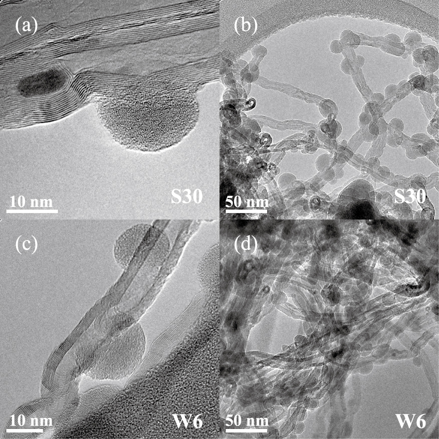
Figs. 6a and 6b present TEM views of the MWCNTs after run S30 performed at 500 °C, as detailed in Table 1. Silicon is present everywhere in the MWCNT balls, taking the form of nanoparticles of 20 nm in average diameter. This indicates that the mass transfer into the porous balls is not a limiting step of the process, as for the SnO2 deposition. The nanoparticles are predominantly present on structural defects of the MWCNT surface.
The conversion rate of silane was 100 %, probably due to the high surface area of the MWCNT powder and to the quite high reactivity of silane.
The silicon nanoparticles are clearly more numerous and smaller than the SnO2 particles. These results mean that the reactivity of silane is higher than that of the SnCl4/H2O mixture. However, a nucleation limitation still exists for Si deposition since the surface coverage of the MWCNT surface is not 100 %. It is well-known that, as detailed in Table 2, when silane is heated to temperatures higher than 370 °C, pyrolysis reactions occur in the gas phase leading to the formation of very reactive unsaturated molecules such as silylene SiH2. It is likely that these unsaturated molecules are the origin of the first formation of nuclei on the MWCNT surface.
They are probably much more reactive than the species formed during the depositions from SnCl4/H2O. However, they are not reactive enough to chemisorb and form nuclei everywhere on the inert MWCNT surface. Once the first Si nuclei are formed on the nanotube surface, the growth is probably easier as shown by Zahi et al. (2011) on SiO2 planar substrates, explaining the 100 % conversion of silane.
In order to intensify the surface reactivity of the MWCNTs, a pre-treatment using water vapour at 650 °C was applied during 60 min at a fluidization ratio of 4 just before the deposition using the conditions of run S30, as detailed in Table 1. The conversion rate of silane for run W6 was still 100 %. As can be seen in Figs. 6c and 6d, no significant difference can be seen regarding the morphology of the deposit between this run and run S30. The size, localisation and surface density of the Si nanoparticles are unchanged. It can be concluded that for the conditions tested, the water pre-treatment has not modified the surface reactivity of the MWCNTs for the silicon deposition from silane.
If we compare with the SnO2 deposition results, the same pre-treatment was applied to the MWCNTs. In the case of SnCl4/H2O, an increase of the deposit nucleation had occurred, whereas this was not the case for silane. As previously explained, SnCl4 needs a preliminary H2O adsorption step for allowing the chemisorption of Sn to occur. It is then logical that the SnO2 deposition is intensified by an H2O pre-treatment. On the contrary, the surface reactivity of the chemical species responsible for silicon deposition is not intensified by the H2O pre-treatment. Previous works (Zahi et al., 2011) about the first steps of nucleation and growth during silicon CVD from silane on planar substrates have shown that substrates covered by hydroxyl (OH) groups involve a quite low surface reactivity of unsaturated species such as SiH2 due to the high electronegativity of the oxygen atom. For the Si FBCVD process, the creation of more defects on the MWCNT surface would probably have been more efficient to increase Si nucleation.
3.4 Fe deposition
Among the possible CVD precursors of iron, ferrocene (Fe(C5H5)2) is an organometallic compound stable in air and non-toxic, quite cheap and easy to sublimate, forming stable vapour to feed the CVD reactor (Philippe, 2006; Senocq et al., 2006) and able to deposit pure iron (Stauf et al., 1987; Dormans, 1991).
As detailed in Table 1, the deposition temperature was fixed at 650 °C, except for nCNT10 (550 °C) because of the reactivity increase of ferrocene induced by the presence of hydrogen (Wasel et al., 2007; Qian et al., 2001).
Under an inert atmosphere (N2), Figs. 7 and 8a show that the deposit occurs in the form of discrete iron-based nanoparticles of 50–500 nm in diameter confined in a graphenic carbon shell and present everywhere in the MWCNT balls. This has been confirmed by SEM-EDX analyses (not shown) at the ball scale.

This uniform distribution indicates that the mass transfer into the porous balls is not a limiting step of the process, as for the previous deposits. But the surface coverage of the MWCNTs is low. So, a nucleation limitation also exists for this deposit. X-Ray Diffraction (XRD) analyses (Fig. 9) indicate that the nanoparticles are composed of iron and iron carbide Fe3C for all runs. A possible explanation is that the homogeneous decomposition of ferrocene under N2 is auto-catalytic beyond 500 °C (Senocq et al., 2006) and forms Fe3C particles (cementite) which can then be captured by the nanotubes of the bed. Some nanoparticles could also directly nucleate on the MWCNT surface, probably on surface defects like for silicon. Some of the nanoparticles seem to catalyse the formation of nanofibres (CNFs) or of large CNTs.

Ferrocene is indeed known to be a precursor of both iron and carbon nanomaterials (Bhatia and Prasad, 2010). Carbon coming from the ligands lost by ferrocene during its decomposition could saturate iron nanoparticles to form Fe3C and then CNTs and/or carbon nanofibres (CNFs).
The conversion rate of ferrocene into iron deposited within the MWCNT balls was deduced from ICP-MS measurements and bed weighing. It is 87 %, as detailed in Table 1. ICP-MS measurements indicate that the powder after run nCNT3 is composed of 11.8 wt% of iron (without removing the initial iron content).
The same deposition conditions were tested after an O3 pre-treatment (nCNT9) in order to increase the surface reactivity of MWCNTs and then the nucleation of iron. TEM images (Fig. 8b) indicate that the deposit produces 10–100-nm-size iron-based particles more uniformly distributed at the TEM scale than previously. The deposited particles are then more numerous and smaller than previously. These two effects and the more uniform presence of nanoparticles on the nanotube surface could be a consequence of ozonation. By grafting oxygen-containing groups (hydroxyl or carboxyl) onto the nanotube surface, ozonation increases the nucleation of iron-based nanoparticles and then the surface reactivity of MWCNTs towards ferrocene and its gaseous products of decomposition. This is confirmed by the ICP-MS iron content of 17.6 wt% in the powder and by the higher ferrocene conversion rate (close to 100 %), as detailed in Table 1. However, the deposited nanoparticles are still covered by graphenic shells, CNFs/CNTs are still formed and the deposit is still composed of Fe and Fe3C (Fig. 9). Moreover, a large amount of amorphous carbon was deposited everywhere.
The addition of H2 at a volume percentage higher than 25 % is known to limit CNF/CNT growth and amorphous carbon formation (Wasel et al., 2007; Qian et al., 2001). Consequently, H2 was added with a H2/N2 ratio of 67/33 vol.% during run nCNT10. TEM images (Fig. 8c) reveal less numerous iron-based nanoparticles which are less uniformly distributed at the TEM scale. These Fe/Fe3C particles are smaller (20–50 nm) and still covered by graphenic shells but no CNFs/CNTs were observed and the large amount of amorphous carbon previously reported is absent. So, the addition of H2 seems to have inhibited the formation of both the amorphous carbon and the CNT/CNFs, but seems also to reduce the nanoparticle nucleation and growth, as confirmed by the ICP-MS iron content of 13.7 wt% and by the ferrocene lower conversion rate (90 %).
According to Senocq et al. (2006), the addition of water vapour to ferrocene could favour the formation of pure iron films under conditions close to ours. The run nCNT13 was then performed in the presence of water vapour. TEM images are shown in Fig. 8d. Less numerous and less uniformly distributed Fe3O4/Fe3C nanoparticles are covered by graphenic shells and have catalysed the formation of large CNFs/CNTs. Their diameter is related to the nanoparticle size, ranging between 10 and 100 nm. The ICP-MS iron content is 12.3 wt%, which is similar to that of run nCNT3. This means that under the conditions tested, the addition of water vapour does not favour the deposition of pure iron nanoparticles as expected. It even seems to lower the ferrocene reactivity in proportion close to that observed in the presence of hydrogen, as indicated by the ferrocene conversion rate of 84 % given in Table 1.
When compared with the two previous deposition experiments (SnO2 and Si), the use of ferrocene involves not only a nucleation limitation on the nanotube surface as strong as for the SnCl4/H2O system, but also a difficulty to form pure iron deposits, which was not the case of the two previous deposits studied. When compared with other works performed on steel, quartz or Si planar substrates (Stauf et al., 1987; Dormans, 1991; Senocq et al., 2006), this difficulty to deposit pure iron is clearly reinforced by the chemical nature of the MWCNT surface. A pre-deposit of TiC as done by Feng and Puddephatt (2007) could improve both the surface reactivity of the MWCNTs and the selectivity of ferrocene decomposition to produce pure iron deposits.
4. Conclusion
Multi-walled carbon nanotubes were decorated by three kinds of nanoparticles from precursors of very different reactivity using the fluidized bed chemical vapour deposition process.
When comparing the results obtained in terms of nucleation of nanoparticles on the nanotube surface, it clearly appears that the intrinsic reactivity of the CVD precursors is a key factor. The most reactive precursor we studied, silane SiH4, forms many silicon nanoparticles of several tens of nanometres on the nanotube surface, without any nanotube pre-treatment. This is not the case with the less reactive SnCl4/H2O system for which the nucleation of SnO2 nanoparticles was favoured by an H2O pre-treatment. A third situation was observed using ferrocene, for which not only a nucleation limitation on the nanotube surface exists, but also a difficulty to obtain pure iron deposits which seems reinforced by the chemical nature of the nanotube surface. However, an ozone pre-treatment of the nanotubes made it possible to increase the iron deposition.
So, the FB-CVD process can successfully decorate carbon nanotubes by metallic or semi-conducting nanoparticles provided that the reactivity of the precursors towards the nanotube surface is high enough. If this is not the case, a dry mode pre-treatment of the nanotubes by ozone or water vapour can be efficient if the surface modification involved is well-suited to the precursor reactivity. The reactive pathways of the precursor must then be analysed accurately before deciding whether to apply a pre-treatment and what kind of pre-treatment.
In comparison with the wet methods, a main advantage of the dry mode pre-treatments in fluidized beds and of the FB-CVD process is that they can treat large amounts of carbon nanotubes, i.e. 100 g at lab-scale and tons at the industrial scale, opening the way for a mass production of decorated MWCNTs for applications such as nano-fillers of innovative multi-functional composite materials or high-capacity anodes for Li-ion batteries.
Acknowledgements
The part of work concerning iron deposition was supported by the French Midi-Pyrénées region and by the Waspe FUI project. The authors thank M. Molinier and E. Prévot from LGC for technical help and ARKEMA for providing the carbon nanotubes.
Author’s short biography
Pierre Lassègue

Pierre Lassègue is a PhD student in the Innovative Multiphase Reactor Engineering Department of the Laboratory of Chemical Engineering at the National Polytechnic Institute of Toulouse. He received his BSc degree in chemistry and physico-chemical processes in 2011 and his two MSc degrees in process engineering and in environment and processes in 2013 from Toulouse University. His research interests concern carbon nanotubes and fluidized bed chemical vapour deposition.
Nicolas Coppey

Dr. Nicolas Coppey is currently working as a laboratory manager at SNAM, a European player collecting and recycling metals from batteries. He is taking part in the development of hydrometallurgy treatment units to optimise recycling performance. He received his PhD. in process engineering and environment from the University of Toulouse in 2013 under the supervision of Prof. Brigitte Caussat. He studied the decoration of carbon nanotubes by silicon nanoparticles and the application as an electrode material in lithium-ion batteries.
Laure Noé

Mrs Laure Noé has been tenured at the French National Research Institute (CNRS) since 1991, where she is currently working as an assistant engineer. She is dedicated to the synthesis and/or characterization of materials (mostly carbon nanoforms, but other nanomaterials as well, and more recently archaeological crafts), formerly regarding their chemical composition by means of chemical analytical routes, nowadays regarding their structural, textural, and chemical features by means of TEM-related methods (HRTEM, electron diffraction, X-EDS). She has co-authored 22 publications in international journals and 37 papers in colloquia and conferences.
Marc Monthioux

Dr. Marc Monthioux is currently working as a research director at the French National Research Institute (CNRS). He has been working on the synthesis and/or structural characterisation of carbon and carbon-containing materials of any kind since 1979. He is currently co-editor of CARBON journal (Elsevier), former chairman of the French Carbon Group (GFEC) and former chairman of the European Carbon Association (ECA). He has (co)authored 18 book chapters, more than 340 papers in conferences, and more than 130 papers in international journals cited more than 5000 times (h = 30).
Brigitte Caussat

Brigitte Caussat is a professor of chemical engineering in the Innovative Multiphase Reactor Engineering Department of the Laboratory of Chemical Engineering at the National Polytechnic Institute of Toulouse. She is an engineer in chemical engineering and received her PhD in 1994. Her research interests concern the chemical vapour deposition processes either on planar substrates to form graphene and thin films, or in fluidized bed to decorate carbon nanotube balls and to coat powders. She is co-author of more than 80 publications, 6 patents and 90 papers.
References
- Ajayan P.M., Ebbesen T.W., Ichihashi T., Iijima S., Tanagaki K., Hiura H., Opening carbon nanotubes with oxygen and implications for filling, Nature, 362 (1993) 522–525.
- Babal A.S., Gupta R., Singh B.P., Singh V.N., Dhakate S.R., Mathur R.B., Mechanical and electrical properties of high performance MWCNT/polycarbonate composites prepared by an industrial viable twin screw extruder with back flow channel, RSCAdv., 4 (2014) 64649–64650.
- Bacsa R., Serp P., Decorated (coated) carbon nanotubes, in: Monthioux M. (Ed.), Carbon meta-nanotubes, synthesis, properties and applications, Wiley, 2012, pp. 163–207.
- Behler K., Osswald S., Ye H., Dimovski S., Gogotsi Y., Effect of thermal treatment on the structure of multiwall carbon nanotubes, J. Nanopart. Res., 8 (2006) 615–625.
- Bhatia R., Prasad V., Synthesis of multiwall carbon nanotubes by chemical vapour deposition of ferrocene alone, Solid State Commun., 150 (2010) 311–315.
- Braga A.F., Moreira S.P., Zampieri P.R., Bacchin J.M.G., Mei P.R., New processes for the production of solar-grade polycrystalline silicon: a review, Solar En. Mat. Solar Cells, 92 (2008) 418–424.
- Coppey N., Nanotubes de carbone décorés par CVD en lit fluidisé: application en batterie lithium-ion, PhD thesis, INP Toulouse, France, 2013.
- Cui L.F., Hu L., Choi J.W., Cui Y., Light-weight free-standing carbon nanotube-silicon films for anodes of lithium ion batteries, ACSNano, 4 (2010) 3671–3678.
- Dasgupta K., Joshi J.B., Banerjee S., Fluidized bed synthesis of carbon nanotubes—A review, Chem. Eng. J., 171 (2011) 841–869.
- Dormans G.J.M., OMCVD of transition metals and their silicides using metallocenes and (di)silane or silicon tetra-bromide, J. Cryst. Growth, 5 (1991) 806–816.
- Emel’yanenko V.N., Verevkin S.P., Krol O.V., Varushchenko R.M., Chelovskaya N.V., Vapour pressures and enthalpies of vapourization of a series of the ferrocene derivatives, J. Chem. Thermodyn., 39 (2007) 594–601.
- Feng M., Puddephatt R.J., Chemical Vapour Deposition of nickel-group metals on multiwall carbon nanotubes, Can. J. Chem., 85 (2007) 645–650.
- Geldart D., Types of gas fluidization, Powder Techn., 7 (1973) 285–292.
- Goulas A., Ruud van Ommen J., Scalable production of nano-structured particles using atomic layer deposition, Kona Powder and Particle Journal, 31 (2014) 234–246.
- Kim J.H., Min B.G., Functionalization of multi-walled carbon nanotube by treatment with dry ozone gas for the enhanced dispersion and adhesion in polymeric composites, Carbon Lett., 11 (2010) 298–303.
- Kuang Q., Li S.F., Xie Z.X., Lin S.C., Zhang X.H., Xie S.Y., Huang R.B., Zheng L.S., Controllable fabrication of SnO2-coated multiwalled carbon nanotubes by Chemical Vapour Deposition, Carbon, 44 (2006) 1166–1172.
- Kunii D., Levenspiel O., Fluidization engineering, second edition, John Wiley & sons Inc., New York, 1991.
- Li C., Hua B., Preparation of nanocrystalline SnO2 thin film coated Al2O3 ultrafine particles by fluidized chemical vapour deposition, Thin Solid Films, 310 (1997) 238–243.
- Li C., Zhao A., Xia W., Liang C., Muhler M., Quantitative studies on the oxygen and nitrogen functionalization of carbon nanotubes performed in the gas phase, J. Phys. Chem. C, 116 (2012) 20930–20936.
- Lin T., Bajpai V., Ji T., Dai L., Chemistry of carbon nanotubes, Aust. J. Chem., 56 (2003) 635–651.
- Liu S.S., Xiao W.D., CFD-PBM coupled simulation of silicon CVD growth in a fluidized bed reactor: Effect of silane pyrolysis kinetic models, Chem. Eng. Sci., 127 (2015) 84–94.
- Lubej M., Plazl I., Theoretical and experimental study of iron catalyst preparation by chemical vapour deposition of ferrocene in air, Chem. Eng. J., 242 (2014) 306–312.
- McEvoy A., Markvart T., Castaner L., Solar Cells: Materials, Manufacture and Operation, Elsevier, second edition, 2013.
- Mendoza F., Hernandez D.M., Makarov V., Febus E., Weiner B.R., Morell G., Room temperature gas sensor based on tin dioxide-carbon nanotubes composite films, Sensors Actuat. B, 190 (2014) 227–233.
- Monthioux M., Serp P., Flahaut E., Laurent C., Peigney A., Razafinimanana M., Bacsa W., Broto J.M., Introduction to carbon nanotubes, in: Brushan B. (Ed.), Springer Handbook of Nanotechnology, Second revised and extended edition, Springer-Verlag, Heidelberg, 2007.
- Philippe R., Synthèse de nanotubes de carbone multi-parois par dépôt chimique en phase vapeur catalytique en lit fluidisé. Nouvelle classe de catalyseurs, étude cinétique et modélisation, PhD thesis, INP Toulouse, France, 2006.
- Qian D., Dickey E.C., Andrews R., Jacques D., Kinetics of carbon nanotube growth by pyrolysis of ferrocene/xylene, Carbon, 1 (2001) 1117–1119.
- Reuge N., Cadoret L., Caussat B., Multifluid eulerian modelling of a silicon fluidized bed Chemical Vapour Deposition process: analysis of various kinetic models, Chem. Eng. J., 148 (2009) 506–516.
- Rong H., Liu Z., Wu Q., Lee Y.H., A facile and efficient gas phase process for purifying single-walled carbon nanotubes, Curr. Appl. Phys., 10 (2010) 1231–1235.
- Ruan S.L., Gao P., Yang X.G., Yua T.X., Toughening high performance ultrahigh molecular weight polyethylene using multiwalled carbon nanotubes, Polymer, 44 (2003) 5643–5654.
- Senocq F., Duminica D., Maury F., Delsol T., Vahlas C., Iron thin films from Fe(CO)5 and FeCp2/H2O under atmospheric pressure, J. Electrochem. Soc., 153 (2006) G1025–G1031.
- Stauf G.T., Driscoll D.C., Dowben P.A., Barfuss S., Grade M., Iron and nickel thin film deposition via metallocene decomposition, Thin Solid Films, 153 (1987) 421–430.
- Vahlas C., Caussat B., Serp P., Angelopoulos G., Principles and applications of CVD powder technology, Mat. Sci. Eng. : Reports, 53 (2006) 1–72.
- Van Mol A.M.B., Chemical Vapour Deposition of tin oxide thin films, Technische Universiteit Eindhoven, 2003, ISBN 90-386-2715-7.
- Vennerberg D.C., Quirino R.L., Jang Y., Kessler M.R., Oxidation behaviour of multi walled carbon nanotubes fluidized with ozone, Appl. Mater. Interfaces, 6 (2014) 1835–1842.
- Wang X.S., Rahman F., Rhodes M.J., Nanoparticle fluidization and Geldart’s classification, Chem. Eng. Sci., 62 (2007) 3455–3461.
- Wartenberg E.W., Ackermann P.W., Electrical and mechanical properties of quenched SnO2 films on glass substrates, Glastechnische Berichte, 61 (1988) 256–262.
- Wasel W., Kuwana K., Reilly P.T.A., Saito K., Experimental characterization of the role of hydrogen in CVD synthesis of MWCNTs, Carbon, 45 (2007) 833–838.
- Wildgoose G.G., Banks C.E., Compton R.G., Metal nanoparticles and related materials supported on carbon nanotubes: methods and applications, Small, 2 (2006) 182–193.
- Xia W., Jin C., Kundu S., Muhler M., A highly efficient gasphase route for the oxygen functionalization of carbon nanotubes based on nitric acid vapour, Carbon, 47 (2009) 919–922.
- Yaws C.L., Chemical Properties Handbook, McGrawHill, 1999.
- Yu H., Zhang Q., Gu G., Wang Y., Luo G., Wei F., Hydrodynamics and gas mixing in a carbon nanotube agglomerate fluidized bed, A.I.Ch.E. Journal, 52 (2006) 4110–4123.
- Zahi I., Mur P., Blaise Ph., Esteve A., Djafari Rouhani M., Vergnes H., Caussat B., Multi scale modelling of silicon nanocrystals synthesis by Low Pressure Chemical Vapour Deposition, Thin Solid Films, 519 (2011) 7650–7658.
- Zhu C., Yu Q., Dave R.N., Gas fluidization characteristics of nanoparticle agglomerates, A.I.Ch.E. Journal, 51 (2005) 426–437.


;%0A%09%09%09newWindow.document.open();%0A%09%09%09newWindow.document.write('<img src=%22./Graphics/33_2016018_10.jpg%22>');%0A%09%09%09newWindow.document.close();%0A%09%09)
;%0A%09%09%09newWindow.document.open();%0A%09%09%09newWindow.document.write('<img src=%22./Graphics/33_2016018_11.jpg%22>');%0A%09%09%09newWindow.document.close();%0A%09%09)
;%0A%09%09%09newWindow.document.open();%0A%09%09%09newWindow.document.write('<img src=%22./Graphics/33_2016018_12.jpg%22>');%0A%09%09%09newWindow.document.close();%0A%09%09)
;%0A%09%09%09newWindow.document.open();%0A%09%09%09newWindow.document.write('<img src=%22./Graphics/33_2016018_13.jpg%22>');%0A%09%09%09newWindow.document.close();%0A%09%09)
;%0A%09%09%09newWindow.document.open();%0A%09%09%09newWindow.document.write('<img src=%22./Graphics/33_2016018_14.jpg%22>');%0A%09%09%09newWindow.document.close();%0A%09%09)