Abstract
This study was conducted to comprehensively investigate the fundamental properties of Ti-6Al-4V alloy produced by the selective laser melting (SLM) method. The examined materials were three SLM materials having different axial directions. For comparison, wrought material of Ti-6Al-4V alloy was also examined. The results showed that the densities of the SLM materials were adequately high and more than 99.9% of that of the wrought material. The SLM materials possessed a columnar microstructure extending along the building direction. This microstructure was mainly composed of the acicular α' martensite phase. Due to the generation of the fine α' phase, the static strength of the SLM materials was markedly higher than that of the wrought material although their elongation was lower. There was anisotropy in the static strength and the ductility of the SLM materials. In spite of the higher tensile strength, the fatigue strength of the SLM materials was much lower than that of the wrought material since molding defects may induce stress concentration and accelerate the generation of fatigue cracks.
1. Introduction
Additive manufacturing (AM) is an innovative processing method that can make metal products with arbitrary three-dimensional shapes from computer-aided design (CAD) data1,2). In this method, a high energy beam is scanned on a powder bed, obeying slice data derived from CAD data. Selectively melted layers are then piled up one-by-one and the desired products are completed. As the high energy beam, a laser beam or an electron beam is generally used. Depending on the kind of beam, AM is categorized as either the selective laser melting (SLM) method used in this study or the electron beam melting (EBM) method.
Medical implants are a suitable application for AM because they have complicated shapes and are made from processing-resistant materials such as titanium alloys. By applying this method, we can create implants with shapes optimized for individual human bodies3,4) and also reduce the implant weight by introducing appropriate open cellular or porous structures5–7). Such tailored implants can reduce the physical burden or damage to the body.
However, some studies have reported that the fatigue strength of Ti-6Al-4V alloy produced by AM is much lower than that of the wrought material8–11). This issue must be overcome in order to apply AM to various products including medical implants. Our previous studies showed that the fatigue strength of Ti-6Al-4V alloy (wrought material) was markedly improved by short-time heat treatment12,13), hybrid surface treatment14,15) and their combination16,17). These treatments have a high potential to improve the fatigue strength of Ti-6Al-4V alloy produced by the AM method.
AM technology has progressed rapidly in recent years. Before investigating the effects of the various treatments, we needed to clarify the current performance of AM materials. Therefore, this study was conducted to comprehensively investigate the fundamental properties of Ti-6Al-4V alloy produced by the SLM method (SLM material).
The examined materials were three SLM materials with different axial directions and the wrought material of Ti-6Al-4V alloy for comparison. We conducted density measurement, observation of molding defects, microstructural observation, electron back-scatter diffraction (EBSD) analysis, X-ray diffraction, hardness measurement, tensile tests, fatigue tests and X-ray residual stress measurement. The fracture surfaces of the tensile and fatigue specimens were observed by scanning electron microscopy (SEM).
2. Materials and Experimental Procedures
2.1 Materials
Table 1 shows the chemical compositions of powders used for the SLM materials. The average diameter of powders was about 50 μm. During the SLM process, the chamber was filled up by shielding gas (Ar) and the oxygen concentration was maintained at 0.07–0.12% to avoid oxidization.
Table 1
Chemical compositions of Ti-6Al-4V alloy (mass%).
| |
Al |
V |
Fe |
O |
H |
C |
N |
Ti |
| Powders (SLM) |
5.79 |
3.80 |
0.18 |
0.12 |
0.002 |
0.01 |
0.007 |
Bal. |
| Wrought material (W) |
6.41 |
4.17 |
0.220 |
0.200 |
0.0043 |
0.004 |
0.003 |
Bal. |
Figure 1 shows the macroscopic features of the round bars produced by the SLM method. The round bars were of diameter 14 mm and length 91 mm. The tilt angles of the axial directions were 0°, 45° and 90° to the plane normal to the building direction. Hereafter, the three SLM materials are called the SLM0, SLM45 and SLM90 materials, according to their respective tilt angles. The building direction and its normal plane are called the BD direction and the BD plane, respectively (Fig. 1). The axial and radial directions of the round bars are called the AD and RD directions, and their normal planes are called the AD and RD planes, respectively.
Wrought material of Ti-6Al-4V alloy (rolled round bars) was prepared for comparison. Its chemical composition is shown in Table 1. The wrought material was annealed at 1023 K for 3.6 ks before machining to the specimen shapes. Hereafter, this material is called W material.
The above materials were machined to the four types of specimen shape shown in Fig. 2. The test sections of all the specimens except those for density measurement were polished to mirror surfaces by emery papers (#400-#2000), alumina powders (#3000) and silicon dioxide suspension (diameter: 80 nm).
2.2 Experimental procedures
The density of each material was measured by the Archimedes' principle using an electronic precision balance. Each density measurement was made three times and the average values were used. The relative densities of the SLM materials were obtained against the density of W material. Molding defects were observed on the cross sections of the SLM materials by an optical microscope and SEM.
The microstructures of W and SLM90 materials were optically observed on the RD and AD planes. Before the observation, the surfaces of the specimens were finished to mirror surfaces in the same manner described in Section 2.1 and then etched with Kroll's etchant. EBSD analysis was also carried out on both planes and the inverse pole figure (IPF) maps, the phase maps and the pole figures were obtained. For all the materials, the X-ray diffraction was conducted on the AD plane. The test conditions were as follows: (1) diffraction angle: 2θ = 30–42°, (2) angle division: 0.01°, (3) scanning speed: 0.017°/s.
Hardness was measured by a micro-Vickers hardness tester under a test force of 2.94 N and retention time of 15 s. The measurement was made ten times each on the AD plane and the average values were taken. The tensile test was performed at room temperature in air. Strain was measured by strain gauges pasted to the test sections. The features of the fractured tensile specimens were macroscopically observed and their fracture surfaces were observed by SEM. The plane-bending fatigue test was carried out under a stress ratio R = −1 and cyclic speed of 25 Hz at room temperature in air. The fatigue fracture surfaces were observed by SEM.
X-ray residual stress measurement was conducted on the test sections of the fatigue specimens in the axial direction (Fig. 2(d)). For the SLM0 and SLM45 materials, the residual stress was measured on both upper and lower sides. The sin2ψ method was used and the peak search was performed with the half-width center method18). The measurement conditions were as follows: (1) X-ray tube: Cu X-ray tube (Kα ray), beam diameter: 1 mm, diffraction angle: 2θ = 142.0°, diffraction plane: (213), ψ angles: 10, 20, 30, 35 and 40°, stress constant: −258.2 MPa/°.
3. Results and Discussion
3.1 Molding defects and densities
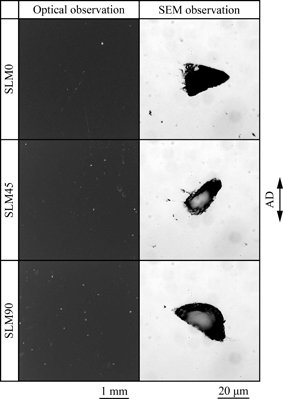
Figure 3 shows the features of the molding defects observed on the cross sections of the SLM materials. In Table 2, the densities and the relative densities are shown. The other results in this table are explained later.
Table 2
Density, relative density, mechanical properties, hardness, residual stress and fatigue strength.
| |
Density,
ρ/(g/cm3) |
Relative
Density
(%) |
Mechanical properties |
Hardness,
H/HV |
Residual stress |
Fatigue
strength,
σW/MPa |
Young’s
modulus,
E/GPa |
Yield
strength,
σY/MPa |
Tensile
strength,
σTS/MPa |
Elongation
(%) |
Reduction
of area
(%) |
Upper
side,
σR/MPa |
Lower
side,
σR/MPa |
| W |
4.433 |
100.00 |
105 |
981 |
1032 |
15 |
47 |
322 |
−115 ± 60 |
− |
620 |
| SLM0 |
4.428 |
99.90 |
114 |
1092 |
1304 |
8.1 |
25 |
408 |
−115 ± 86 |
−93 ± 67 |
460 |
| SLM45 |
4.428 |
99.90 |
122 |
1147 |
1344 |
8.1 |
25 |
401 |
−135 ± 23 |
−239 ± 55 |
400 |
| SLM90 |
4.431 |
99.97 |
114 |
1010 |
1270 |
9.1 |
46 |
396 |
−195 ± 48 |
− |
400 |
As shown in Fig. 3, there were small molding defects in the SLM materials. It has been reported that such molding defects are formed in the SLM process by trapped shielding gas and insufficient melting of powders11). Since the molding defects were very small (diameter 30–40 μm), their total volume was small. As a result, the densities of the SLM materials were adequately high and more than 99.9% of that of W material (Table 2).
3.2 Microstructures
Figure 4 shows the optically observed microstructures of W and SLM90 materials. This figure includes the IPF maps and the phase maps obtained by the EBSD analysis. Figure 5 shows the pole figures of the above materials concerning the α phase (hcp) and the β phase (bcc). Figure 6 shows the profiles of the X-ray diffraction obtained from all the materials.
In W material, the X-ray diffraction profile showed the microstructure to consist of the α phase and the β phase (Fig. 6). As understood from Fig. 4, the α phase was equiaxial and the fine β phase existed around α grains. Its pole figures showed that the α phase possessed one of the typical textures (basal/transvers texture) developed by rolling (Fig. 5)19).
As shown in Fig. 4, the microstructure of the SLM material was columnar and completely different from that of W material. Hereafter, this microstructure is called “columnar microstructure”. Since the columnar microstructure was grown in the BD direction during the SLM process, it looked like a bundle of small columns when observed on the BD plane. According to Refs. 9,20,21), the above microstructure is typical in SLM and EBM materials made from powders of Ti-6Al-4V alloy.
The following mechanism has been proposed to explain the formation of the columnar microstructure21): In the SLM process, laser irradiation melts newly-fed powders on the previously solidified layers. Under the melted layer, the previously solidified layers are heated beyond the β transus temperature (1271 K) and retransformed to the β phase. Epitaxial growth then occurs from the retransformed layers into the melted layer. This process is repeated and the columnar microstructure grows in the BD direction.
As understood from Fig. 4, the columnar microstructure was mainly composed of a fine acicular phase. In the SLM process, the β phase is rapidly cooled by the shielding gas after the epitaxial growth mentioned above. Therefore, we considered that the generated acicular phase was the α' martensite phase. The same conclusion has been drawn in other studies21,22). Before the transformation to the α' phase, the prior β phase in each columnar part had the same orientation, resulting from the epitaxial growth. As a result, the generated α' phase possessed a crystallographic texture (Fig. 5) and its orientation in each columnar part belonged to the same variants (IPF map in Fig. 4)22,23).
The very fine β phase was also observed in the phase map of the SLM material (Fig. 4). As understood from Fig. 5 (white circles), there was a Burger's orientation relationship ((0002)α//{110}β) between the α (α') phase and the β phase on the AD (BD) plane. In the profiles of the X-ray diffraction (Fig. 6), the peaks of the α' phase were not recognized. The crystal structures of the α and α' phases are hexagonal close-packed (hcp) structures. Therefore, their peaks are, in general, somewhat difficult to separate clearly. Moreover, no peak corresponding to the β phase was found in the SLM materials. One of the possible causes for the above discrepancy was considered to be as follows:
Since Ti-6Al-4V alloy was rapidly heated beyond the β transus temperature and cooled, the α' phase was generated. At the same time, the β phase may partially remain as a metastable phase due to insufficient diffusion of the β stabilizer (V)24). It was considered that the remaining β phase was metastable in the SLM materials because laser-irradiated points are rapidly heated and cooled in the SLM process. According to Ref. 25), since the inter-planar spacing is nearly the same between the α' phase and the metastable β phase, their diffraction angles are almost the same. As a result, the X-ray diffraction was not able to differentiate the β phase from the α' phase in the SLM materials24,25).
3.3 Mechanical properties
Table 2 shows the mechanical properties and hardnesses of all the materials. Figure 7 shows the features of the tensile fracture surfaces and the fractured specimens.
As mentioned in the previous section, the columnar microstructure of the SLM materials was mainly composed of the α' phase. This meant that rapid heating and cooling in the SLM process had a heat treatment effect similar to the short-time heat treatment12,13,25). Indeed, the static strength (yield strength and tensile strength) and the hardness of the SLM materials were much higher than those of W material (Table 2).
The columnar microstructure of the SLM materials grew in the specific direction (BD direction) and the crystallographic texture formed. Consequently, an anisotropy was induced in the static strength. SLM45 material showed the highest static strength among the SLM materials.
As understood from Fig. 7, the fracture surfaces of the SLM materials showed ductile features with dimples. However, their elongation was lower than that of W material.
The ductility of the wrought material (Ti-6Al-4V alloy) heated over the β transus temperature, in general, is low because its microstructure exhibits the acicular α phase (Widmanstätten structure) in addition to growth of the prior β grains. According to our previous study, moreover, when short-time heat treatment (heating time 60 s) was performed above the β transus temperature, the ductility of the wrought material (Ti-6Al-4V alloy) was greatly decreased because of the grown prior β grains composed of the α' phase26). From the above factors, we considered that the coarse columnar microstructure caused the reduction of the elongation in the SLM materials.
SLM90 material showed cup-and-cone type fracture and its reduction of area was as high as that of W material. In contrast, SLM0 and SLM45 materials showed different fracture features and their reduction of area was lower. We considered that the growth direction of the columnar microstructure and the orientation of the crystallographic texture induced an anisotropy in the plastic deformation ability.
3.4 Fatigue properties
Figure 8 shows the S-N curves of all the materials. In this figure, a dash mark means that fatigue cracks were generated from internal molding defects. Figure 9 shows the fatigue fracture surfaces near the crack initiation sites. In Table 2, the residual stress and the fatigue strength of each material are shown. For SLM0 and SLM45 materials, the residual stresses were measured on both upper and lower sides of the fatigue specimens (Fig. 2(d)).
In spite of the higher static strength of the SLM materials, their fatigue strength was markedly lower than that of W material as seen from Fig. 8 and Table 2. It has been reported by Refs. 8–11,21) that Ti-6Al-4V alloy produced by AM has low fatigue strength.
The fracture surface of W material showed that the fatigue crack was generated from the surface and propagated inside in a radial pattern (Fig. 9). In contrast, the fracture surfaces of the SLM materials revealed that the fatigue cracks developed from molding defects. If many fairly large defects were formed in SLM materials and mainly controlled their fatigue life, such large defects should have been found on the fatigue fracture surfaces. However, the sizes of the molding defects observed on the fatigue fracture surfaces were around 30–50 μm (Fig. 9). The sizes of the observed molding defects were almost the same as those of the typical defects shown in Fig. 3. In the scope of this study, therefore, it was considered that the relatively small molding defects existing near the surfaces controlled the fatigue properties of SLM materials.
In general, once a fatigue crack is generated in titanium, it continues to propagate without stopping until final fracture27). That is, since the fatigue strength of titanium is strongly controlled by the stress amplitude at which a crack is generated, it is sensitive to the stress concentration. As a result, the stress concentration by molding defects accelerated the initiation of fatigue cracks and reduced the fatigue strengths of the SLM materials.
In Ref. 28), Ti-6Al-4V alloy (wrought material) was fatigue-tested under vacuum conditions. According to this reference, oxygen absorption on the “fresh” slip planes and newly formed crack surfaces was suppressed under the vacuum conditions, so that reverse slips and re-adhesion of crack surfaces were induced. As a result, the threshold of the stress intensity factor range became higher and the crack growth rate was reduced under the vacuum conditions. In the molding defects of SLM materials, there was a high possibility that the oxygen content was very low because the chamber was filled up by shielding gas (Ar) during the SLM process. Therefore, it can be considered that the crack initiation and propagation from the molding defects was more difficult from the internal defects than from the surface defects.
Figure 8 indicates a large data spread in the fatigue life of the SLM materials. Based on the consideration mentioned above, the generation and propagation of fatigue cracks from internal molding defects was more difficult than those from the surface. As a result, the fatigue life of the SLM materials was longer when the cracks developed from the internal molding defects. The above consideration suggested that the positional distribution of the molding defects affected the fatigue life of the SLM materials and caused the large data spread.
The fatigue strength of SLM0 material was slightly higher than those of SLM45 and SLM90 materials. For the wrought material of Ti-6Al-4V alloy, the influence of the texture on the fatigue strength has been reported by Ref. 29). In the SLM materials, however, the positional distribution of the molding defects was the factor that most greatly affected the fatigue life, as mentioned above. As a result, we considered that the difference in the fatigue strength of the SLM materials was probably caused by the presence of molding defects at the surfaces of the specimens.
As shown in Table 2, although compressive residual stress was induced at the surfaces of all the materials, its absolute values were not so high. Within the scope of this study, no relationship was found between the residual stress and the fatigue strength. As mentioned, the fatigue cracks were generated in the SLM materials from not only the surfaces but also from the inside. In future, therefore, further residual stress measurement through the whole cross-sectional area will be needed to clarify its influence on fatigue strength.
4. Conclusions
(1) Small molding defects were formed in the SLM materials. The densities of the SLM materials were adequately high and more than 99.9% of that of the wrought material.
(2) The SLM materials had a columnar microstructure extending along the building direction. The inside of this microstructure was mainly composed of the fine acicular α' martensite phase.
(3) The static strength of the SLM materials was markedly higher than that of the wrought material although their elongation was lower. There was an anisotropy in the static strength and the ductility of the SLM materials.
(4) In spite of the higher tensile strength, the fatigue strength of the SLM materials was much lower than that of the wrought material since the molding defects may induce stress concentration and accelerate the generation of fatigue cracks.
Acknowledgments
This study was supported by the Japan Society for the Promotion of Science, Grants-in-Aid for Scientific Research (B), 2015–2018, No.15H03892 and by the Light Metal Educational Foundation, Inc., 2015–2016. The authors sincerely thank Neturen Co. Ltd. for the X-ray residual stress measurement.
REFERENCES
- 1) N. Guo and M.C. Leu: Front. Mech. Eng. 8 (2013) 215–243. 10.1007/s11465-013-0248-8
- 2) W.E. Frazier: J. Mater. Eng. Perform. 23 (2014) 1917–1928. 10.1007/s11665-014-0958-z
- 3) L.E. Murra, S.A. Quinonesb, S.M. Gaytana, M.I. Lopeza, A. Rodelaa, E.Y. Marineza, D.H. Hernandeza, E. Martineza, F. Medinac and R.B. Wickerc: J. Mech. Behav. Biomed. Mater. 2 (2009) 23–32.
- 4) H. Yoshikawa, A. Matsuoka, T. Nakano, Y. Nakashima: The development of artificial joints -from the history to future prospects-, (Nihon Igakukan, 2013) pp.245–280 (in Japanese).
- 5) L.E. Murr, S.M. Gaytan, F. Medina, H. Lopez, E. Martinez, B.I. Machado, D.H. Herzandez, L. Martinez, M.I. Lopez, R.B. Wicker and J. Bracke: Phil. Trans. R. Soc. A 368 (2010) 1999–2032. 10.1098/rsta.2010.0010
- 6) T. Nakano and W. Fujitani: ISIJ Int. 51 (2011) 562–268.
- 7) N. Ikeo, T. Ishimoto, H. Fukuda and T. Nakano: Adv. Mater. Res. 49 (2012) 142–145.
- 8) E. Wycisk, C. Emmelmann, S. Siddique and F. Walther: Adv. Mater. Res. 816–817 (2013) 134–139. 10.4028/www.scientific.net/AMR.816-817.134
- 9) P. Edwards and M. Ramulu: Mater. Sci. Eng. A 598 (2014) 327–337. 10.1016/j.msea.2014.01.041
- 10) S. Leuders, T. Lieneke, S. Lammers, T. Troster and T. Niendori: J. Mater. Res. 29 (2014) 1911–1919. 10.1557/jmr.2014.157
- 11) Q. Liu, J. Elambasseril, S. Sun, M. Leary, M. Brandt and P.K. Sharp: Adv. Mater. Res. 891–892 (2014) 1519–1524. 10.4028/www.scientific.net/AMR.891-892.1519
- 12) S. Tanaka, T. Morita, K. Shinoda: Proc. 13th Inter. Conf. Fract. (2013) S18-S10.
- 13) T. Morita, S. Tanaka and S. Ninomiya: Mater. Sci. Eng. A 669 (2016) 127–133. 10.1016/j.msea.2016.05.071
- 14) T. Morita, N. Uehigashi and C. Kagaya: Mater. Trans. 54 (2013) 22–27. 10.2320/matertrans.M2012262
- 15) T. Morita, N. Uehigashi and C. Kagaya: Mater. Trans. 54 (2013) 1719–1724. 10.2320/matertrans.M2013228
- 16) T. Morita, K. Asakura and C. Kagaya: Mater. Sci. Eng. A 618 (2014) 438–446. 10.1016/j.msea.2014.09.042
- 17) C. Tsuda, T. Morita, S. Kariya and C. Kagaya: J. Jpn. Inst. Met. Mater. 79 (2015) 195–202 (in Japanese). 10.2320/jinstmet.J2014059
- 18) Edited by Society of Material Science, Japan: Standard for X-ray residual measurement method (JSMS-SD-5-02), (Society of Material Science, Japan, 2002), pp.8–15, pp.40–41 (in Japanese).
- 19) G. Lutjering, J.C. Williams: Titanium, (Springer, 2003) p. 220.
- 20) S.S. Al-Bermani, M.L. Blackmore, W. Zhang and I. Todd: Metall. Mater. Trans., A 41 (2010) 3422–3434. 10.1007/s11661-010-0397-x
- 21) H.K. Rafi, N.V. Karthik, H. Gong, T.L. Starr and B.E. Stucker: J. Mater. Eng. Perform. 22 (2013) 3872–3883. 10.1007/s11665-013-0658-0
- 22) M. Simonelli, Y.Y. Tse and C. Tuck: Metall. Mater. Trans., A 45 (2014) 2863–2872. 10.1007/s11661-014-2218-0
- 23) N. Stanford and P.S. Bate: Acta Mater. 52 (2004) 5215–5224. 10.1016/j.actamat.2004.07.034
- 24) T. Morita, K. Hatsuoka, T. Iizuka and K. Kawasaki: Mater. Trans. 46 (2005) 1681–1686. 10.2320/matertrans.46.1681
- 25) M.A. Imam and C.M. Gilmore: Metal. Trans. A 14 (1983) 233–240. 10.1007/BF02651620
- 26) T. Morita, W. Niwayama, K. Kawasaki and Y. Misaka: Trans. JSME A 64 (1998) 2115–2120 (in Jpanese). 10.1299/kikaia.64.2115
- 27) K. Takao, H. Nisitani: Proc. 2nd Int. Conf. Fatigue (Fatigue Thresholds II, 1984) 827–834.
- 28) H. Oguma and T. Nakamura: J. Soc. Mater. Sci., Japan 60 (2011) 1072–1078 (in Japanese). 10.2472/jsms.60.1072
- 29) M. Peters, A. Gysler and G. Lutjering: Metal. Trans. A 15 (1984) 1597–1605. 10.1007/BF02657799