Abstract
Typically, bismuth added in traditional Cu–Zn brass segregates as films or particles along the alpha-beta phase boundary and induces cracks after casting. The present work investigated the bismuth formation in lead-free Cu–Zn–Si yellow brass with various amounts of recycled bismuth–tin (Bi–Sn) solder. The results showed that no bismuth film segregated at the phase boundaries. In contrast, round particles of bismuth formed in the beta phase and at the alpha-beta phase boundaries when added 1 mass% Bi–Sn alloy and the bismuth particles embedded only in the alpha phase when added 2 to 4 mass% Bi–Sn alloy, respectively. The morphology of the fracture surfaces was significantly modified when Bi–Sn alloy content was increased. More importantly, there was no crack observed in as-cast samples and samples did not subject to any heat treatment process unlike the bismuth formation in other work. Thus, this work suggests that the addition of recycled Bi–Sn solder in lead-free Cu–Zn–Si yellow brass is beneficial to avoid cracks in castings and offer an original lead-free brass alloy with superior properties.
1. Introduction
Historically, lead has been used in brass alloys in order to improve the machinability. The lead segregates into small globules, which are dispersed throughout the microstructure, and act as excellent chip breakers and as a tool lubricant.1) However, the production of leaded brasses in recent years has been limited due to the toxicity of lead to human health and the environment.2) Therefore, lead has been replaced with distinctive elements including magnesium, aluminum, silicon, antimony and tin.3–11) Several researchers have also produced lead-free brasses by powder metallurgy processes with additions of titanium, magnesium, tin, graphite, bismuth and chromium.12–19)
Recently, bismuth has been added to certain copper alloys to enhance the machinability.20,21) Bismuth has similar properties to lead including low melting point and no solubility in copper. However, bismuth in copper alloys segregated in form of thin films along the grain boundaries. There are many effects caused by grain boundaries segregation such as enhanced creep embrittlement, temper embrittlement that enhanced grain boundaries stress corrosion cracking, hydrogen embrittlement.22,23)
Ando et al.24) suggested that, the dispersion of bismuth in form of particles could be produced by heat treatment process. However, their alloys cracked during casting, extrusion and machining. A previous research reported that adding phosphorous, indium or tin could reduce the embrittlement of Cu–Zn–Bi alloy.25) Jang et al.26) found that bismuth could form globules of a bismuth intermetallic compound with Ce, La, Nd and other rare earth elements and were present at the phase boundaries. In addition, Chih-Chun et al. and Martinez-Hernandez et al.27,28) suggested that bismuth in Cu–Zn–Al alloys precipitated as bismuth particles at the phase boundaries, which resulted in cracks on the surface of castings and promoted embrittlement during machining process.
On one hand, it is known that metallurgical and micromechanical aspects controlling the microstructural array, unsoundness, strength and ductility of number materials and alloys are complex.29–31) On the other hand, it is also recognized that microstructural array, grain morphology, solute concentration, dispersion of second phases and inclusions have important roles on its resulting properties.31–34) These mentioned parameters seem to constitute obstacles to slip, which can be intimately be associated with mechanical behavior.32–34)
Thus, this work proposed a new idea of adding Bi–Sn alloy as an alternative to lead. An attempt to prevent bismuth segregation at the phase boundaries in lead-free yellow brass was successful. The effects of systematically adding Bi–Sn alloy on the microstructures, mechanical properties and fracture morphology were investigated.
2. Experimental Procedure
Lead-free brass in this study consisted of Cu–38Zn with 0.5 mass% silicon with various 1–4 mass% Bi–Sn alloys, as described in details in our previous work.21) The alloys were prepared with high purity copper (Bangkok Assays, ≥99.5%), zinc (Padaeng Industry, 99.9%), silicon (S.M. Chemical Supplies, 99.5%), and a recycled electronic solder, which is an alloy composed of 52Bi–48Sn. The alloys were melted in a graphite crucible, using a medium frequency induction furnace at a constant temperature of 1050°C. The temperature was measured with a type K thermocouple (OMRON) with an accuracy of ±2°C. After melting and homogenization, the molten alloys were poured into a cylindrical fiber-glass mold with a diameter of 25 mm and the length of 150 mm. The castings were allowed to cool in the mold for 5 minutes, then removed and air cooled to room temperature. The specimens were mechanically polished and etched in a solution of FeCl3 (5 g), HCl (50 ml) and H2O (100 ml). The microstructures of the as-cast samples were observed by scanning electron microscope (SEM). The chemical analysis of the phases and maps of elemental distribution were determined by energy dispersive x-ray spectrometer (EDS-JSM-6610, JEOL). The phase identifications were analyzed by powder X-ray diffraction (XRD) and database from the Joint Committee on Powder Diffraction Standards (JCDPS).
Microhardness testing was performed using a Vickers microhardness tester (Shimadzu, HMV-2000) with an indentation load of 200 g, for 10 sec at room temperature. The hardness values were calculated by averaging five indentations. The chemical compositions of the as-cast samples were analyzed by X-ray fluorescence spectrometry (Thermo Scientific, Niton XL3-56741). The mechanical properties were measured by tensile testing with a Lloyd UTM using a crosshead speed of 10 mm/min, according to ASTM standard E8. The reported results were obtained by averaging the results of three samples.
3. Results and Discussions
3.1 Microstructures and chemical analysis
BSE/SEM micrographs of the as-cast samples were shown in Fig. 1. The micrographs showed a dual phase microstructure consisting of a solid solution of alpha phase (fcc) and beta phase (bcc). The addition of 1–4 mass% Bi–Sn alloy to the Cu–38Zn–0.5Si brass resulted in microstructural modifications, primarily phase size reduction as shown in Fig. 1(a)–1(d), respectively. The phase transformation of these alloys related with zinc equivalent were explained in details in our previous work.21)
In addition, Fig. 1(a) of specimens with 1 mass% Bi–Sn alloy additions showed that the bismuth particles were embedded in the beta phase and at the alpha-beta phase boundaries. When adding 2 to 4 mass% Bi–Sn alloy, shown in Fig. 1(b)–1(d), respectively, the bismuth particles were embedded only in the alpha phase, which will be discussed later in some details. The Bi particles were larger and there were more of them with increasing Bi–Sn alloy content.
The chemical analysis of the phases and the concentration distribution of elements were determined by X-ray energy dispersive spectroscopy (EDS). The EDS point analysis and the elemental maps were shown in Fig. 2 and 3, respectively. The EDS plot of the area 1 indicated that the particle was pure bismuth (Fig. 2(b)). Due to bismuth has a very low solubility in the solid solution of copper–zinc. Hence, it was solidified at low temperature (∼271°C) and formed pure bismuth particles distributed throughout the microstructure.35) The EDS plot of the area 2 showed an alpha phase and of the area 3 was a beta phase as illustrated in Fig. 2(c) and (d), respectively. The beta phase contained a higher content of zinc, silicon and tin than the alpha phase in the area 2. This was confirmed by the X-ray elemental maps as shown in Fig. 3, which also indicated that a high concentration of tin was observed in the beta phase around the pure bismuth particles and at the alpha phase boundaries.


Presence of tin at the phase boundaries can be explained by the segregation mechanism. Since the total zinc equivalent of the studied composition was in the range of 41–44 as reported in our previous work.21) In the case of 44% zinc equivalent as shown in Fig. 4, when the temperature of the liquid alloy was cooled to 908°C at the liquidus line (at point A), the freezing began where the β phase crystallized. When the temperature dropped to point B, fraction of the β phase increased. The solidification was completed when the system reached 875°C, the solidus at point C. The freezing range temperature was 908–875 = 33°C. Solidification of the Cu–Zn alloys in this work can be classified as a short freezing range (liquidus to solidus interval < 50°C).36) The transformation of L→L+β→β was in the equilibrium and zinc atoms could diffuse only in short range. Therefore, the structure consisted entirely of the beta phase where tin could dissolve and no gamma phase was generated.

When temperature was reduced below 500–750°C (at α+β boundary), the alpha phase began to precipitate at the beta phase boundaries and increased in quantity as the temperature dropped. Tin was diffused from beta to alpha phase according to the solid solubility limits. In the last solid transformation, the excess concentration of tin in alpha phase would agglomerate at the alpha/beta phase boundaries.
To identify the phase formation, X-ray diffraction patterns were shown in Fig. 5. Lead-free Cu–38Zn–0.5Si consisted of the alpha and beta phases. The additions of 1–4 mass% Bi–Sn alloys resulted in the third phase of pure bismuth formation. This confirmed the above result that the third phase formed by adding Bi–Sn was a pure bismuth phase. It is evidenced that microstructures of all studied alloys are consisted of only alpha and beta phases without any gamma phase.
The EDS and XRD results demonstrated dissolution behavior of bismuth and tin, which was the same as when adding pure bismuth and pure tin. It was also noted that tin was dissolved in the solid solution beta phase more than that in the alpha phase, which was in accordance with the previous research.7) While bismuth was insoluble in the brass alloy and formed only pure bismuth particles as shown in this study.
It was noted that the microstructures observed in the present work were different from a traditional Cu–Zn–Bi alloy microstructure as shown schematically in Fig. 6(a). Typically, bismuth formed a thin film along the phase boundaries. Jang et al.26) founded that addition of Misch (Ms) metal, which could be a mixture of Ce, La, Nd, and other rare earth elements, could form globules of a Bi–Ms intermetallic compound, which tended to be present at the phase boundaries, as shown in Fig. 6(b). In addition, Chih-Chun et al. and Martinez-Hernandez et al.27,28) showed that bismuth additions to Cu–Zn–Al alloys precipitated as bismuth particles at the phase boundaries, as shown in Fig. 6(c), which resulted in cracks on the surface of castings and promoted embrittlement during machining.

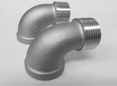
Compared to other works,24,28) there was no crack observed after casting and machining in the present samples as shown in Fig. 7. It is suggested that the addition of bismuth together with tin more than 1 mass% could prevent both the formation of bismuth films and bismuth particles along the phase boundaries (Fig. 6(d)). This is due to tin has higher surface tension than bismuth.37) Thus, the area with higher tin concentration exhibited higher surface tension, which resulting in decreasing the wettability of bismuth particles.38) The chemical phase analyses and elemental maps (Fig. 2 and Fig. 3) supported that tin dissolved in the beta phase more than that in the alpha phase. Moreover, the high concentration of tin around bismuth particles and at the alpha boundaries were evidence. Consequently, in the beta and the alpha phase boundaries were extremely strong surface tension than in the alpha phase. Hence, the bismuth particles were dewetting in these areas. This is the reason why the bismuth particles were not embedded in the beta phase and at the phase boundaries. This was significant in preventing embrittlement of ternary Cu–Zn–Bi alloys and was beneficial for the usability of the alloys.
The results suggested that the addition of 1–4 mass% Bi–Sn alloy had a significant influence on enhancing the hardness from 99 to 149 HV. Due to the microstructural modification from both the phase size refinement by bismuth additions and the solid solution strengthening by tin additions, the volume fraction of beta phase was increased. The beta phase (bcc) was harder than the alpha phase (fcc). Thus, increasing the hardness through dislocation movement obstruction. Conversely, the tensile strength decreased (from 378 to 329 MPa) with increasing Bi–Sn alloy 1–3 mass% and the elongation decreased (from 28% to 7%) with increasing Bi–Sn alloy up to 4 mass%, which was a consequence of the increased volume fraction and sizes of bismuth particles.
This trend of the mechanical properties was similar to that of the conventional leaded brasses whereby higher lead content and large lead particles decreased tensile strength and elongation.39,40) On the other hand, tensile strength (332 MPa) of lead-free brass with 4 mass% Bi–Sn alloy addition was slightly higher than that (329 MPa) of lead-free brass with 3 mass% Bi–Sn alloy addition, which was a result of increasing amount of dissolved tin in the beta phase. The effect of the tin on increasing the strength is more than the effect of the bismuth on decreasing the strength.
3.3 Fracture surface morphology
The SEM micrographs of fracture surface morphology of tensile test specimens were shown in Fig. 8. It illustrated that the fracture surface of lead-free brass without Bi–Sn alloy addition (Fig. 8(a)) showed equiaxed dimples and a few conical dimples, which was a typical ductile dimples rupture. The fracture feature of lead-free brass with 1 mass% Bi–Sn alloy addition revealed a mixture of coarse and fine dimples with bismuth particles embedded in the bottom of the dimples and that some regions contained fracture bismuth particles, as shown in Fig. 8(b). The 2 to 3 mass% Bi–Sn alloys changed the fracture features from a mixture of coarse and fine shallow dimples to coarse and large shallow dimples, as shown in Fig. 8(c) and (d), respectively. Lead-free brass with 4 mass% Bi–Sn alloy shown cleavage feature and large shallow dimples with some larger fracture bismuth particles, as shown in Fig. 8(e).

The results demonstrated that under a uniaxial tensile force, the bismuth particles acted as microvoid initiators,40) shown schematically in Fig. 9(a). They were formed at the boundary between the bismuth particles and the matrix phase (Fig. 9(b)). These microvoids continued to grow by a slip and necking process until adjacent microvoids begin to coalescence, (Fig. 9(c)) and formed a microcrack, which then propagated in the direction normal to the tensile stress axis (Fig. 9(d)). The crack then rapidly propagated through the periphery along the shear plane, leaving the characteristic cup and cone fracture surfaces, shown in (Fig. 9(e)). The process of microvoid formation from the bismuth particles was seen as dimples on the fracture surface. Since, the bismuth particles were randomly located within the microstructure, the microvoids were also formed at random, which gave the fracture surface an irregular, dimpled appearance. It is noted that the dimple size in the present alloys is directly proportionally to the bismuth particle sizes.

4. Conclusions
The investigation of adding various amount of bismuth–tin alloy on bismuth formation in lead-Free Cu–Zn–Si yellow brass could be concluded as the following:
-
1.
The addition of 1–4 mass% Bi–Sn alloys prevented the formation of a bismuth film or particles along the phase boundaries and no cracks were observed after casting.
-
2.
The addition of 1 mass% Bi–Sn alloys generated bismuth particles located in the beta phase and at the alpha-beta phase boundaries. An increasing of Bi–Sn alloy content from 1 mass% to 2–4 mass% resulted in bismuth particles embedded in the alpha phase only.
-
3.
The lead-free Cu–Zn–Si yellow brass with 1–3 mass% Bi–Sn alloy contents enhanced the hardness and exhibited good tensile properties. The morphology of fracture surface displayed ductile fracture behavior.
Acknowledgment
This work was supported by the Thailand Research Fund, Research and Researcher for Industries [No. PHD56I0064] and Smilebrass Company Limited. The authors would like to thank Prof. Supapan Seraphin for a fruitful discussion.
REFERENCES
- 1) A. Wolfenden and P.K. Wright: Metal. Technol. 6 (1979) 297–302.
- 2) T.C. Hutchinson and K.M. Meema: Lead, mercury, cadmium and arsenic in the environment, (John Wiley & Sons, New York, 1987).
- 3) C. Xu, Z. Hu and S. Zhang: Pub. No. US 2010/0080731 A1 (2010).
- 4) C. Xu, Z. Hu and S. Zhang: Pub. No. US 2010/0155011 A1 (2010).
- 5) C. Xu, Z. Hu and S. Zhang: Patent No. US 8,273,193 B2 (2012).
- 6) M. Zhang, S. Zhang, H. Lou and X. Xie: Patent No. US 7,628,872 B2 (2009).
- 7) S. Puathawee, S. Rojananan and S. Rojananan: Adv. Mater. Res. 802 (2013) 169–173.
- 8) C. Vilarinho, D. Soares and F. Castro: J. Alloys Compd. 379 (2004) 161–165.
- 9) Q. Zhu, W. Wu, K. Lui, G. Chen and W. Chen: Sci. China, Ser. E 52 (2009) 2172–2174.
- 10) C. Vilarinho, J.P. Davim, D. Soares, F. Castro and J. Barbosa: J. Mater. Process. Technol. 170 (2005) 441–447.
- 11) M.A. Taha, N.A. El-Mahallawy, R.M. Hammouda, T.M. Moussa and M.H. Gheith: Ain Shams Eng. J. 3 (2012) 383–392.
- 12) H. Imai, S. Li, H. Atsumi, Y. Kosaka, A. Kojima and K. Kondoh: Mater. Trans. 51 (2010) 855–859.
- 13) H. Imai, Y. Kosaka, A. Kojima, S. Li, K. Kondoh, J. Umeda and H. Atsumi: Powder Technol. 198 (2010) 417–421.
- 14) H. Atsumi, H. Imai, S. Li, K. Kondoh, Y. Kosaka and A. Kojima: Mater. Chem. Phys. 135 (2012) 554–562.
- 15) S. Li, K. Kondoh, H. Imai and H. Atsumi: Powder Technol. 205 (2011) 242–249.
- 16) S. Li, H. Imai, H. Atsumi, K. Kondoh, A. Kojima, Y. Kosaka, K. Yamamoto and M. Takahashi: Mater. Sci. Eng. A 535 (2012) 22–31.
- 17) S. Li, H. Imai, H. Atsumi and K. Kondoh: J. Mater. Eng. Perform. 22 (2013) 3168–3174.
- 18) H. Imai, S. Li, K. Kondoh, Y. Kosaka, A. Kojima, H. Atsumi and J. Umeda: Mater. Trans. 52 (2011) 1426–1430.
- 19) H. Imai, S. Li, K. Kondoh, Y. Kosaka, T. Okada, K. Yamamoto, M. Takahashi and J. Umeda: Mater. Trans. 55 (2014) 528–533.
- 20) A. Sandvig, G. Boyd, G. Kirmeyer, M. Edward, S. Triantafyllidou and B.M. Murphy: (Awwa Research Foundation, U.S.A., 2007).
- 21) P. Suksongkarm, S. Rojananan and S. Rojananan: Mater. Trans. 58 (2017) 1754–1760.
- 22) S. Hofmann and P. Lejcek: Interface Sci. 3 (1996) 241–267.
- 23) G. Pantazopoulos: J. Mater. Eng. Perform. 11 (2002) 402–407.
- 24) T. Ando and T. Mochizuki: Patent No. EP 1598436 A1 (2005) 25.
- 25) J.T. Plewes and D.N. Loiacono: Adv. Mater. Process. 140 (1991) 23–27.
- 26) Y. Jang, S. Kim and S. Han: Metall. Mater. Trans. A 36 (2005) 1060–1065.
- 27) C.-C. Hsieh, J.-S. Wang, P.T.-Y. Wu and W. Wu: Met. Mater. Int. 19 (2013) 1173–1179.
- 28) M. Martinez-Hernandez, A. Juarez-Hernandez and C. Gonzalez-Rivera: Eng. Fail. Anal. 28 (2013) 63–68.
- 29) L.C. Peixoto, A.D. Bortolozo, A. Garcia and W.R. Osório: J. Mater. Eng. Perform. 25 (2016) 2211–2221.
- 30) F. Ochoa, J.J. Williams and N. Chawla: J. Electron. Mater. 32 (2003) 1414–1420.
- 31) W.R. Osório, C.A. Siqueira, C.M.A. Freire and A. Garcia: Rev. Metal. Madrid. (2005) 176–180.
- 32) L.M. Satizabal, D. Costa, G.O. Hainick, D.R. Moura, A.D. Bortolozo and W.R. Osório: Metall. Mater. Trans. A 48 (2017) 1880–1892.
- 33) W.R. Osório, L.R. Garcia, L.C. Peixoto and A. Garcia: Mater. Des. 32 (2011) 4763–4772.
- 34) L.C. Peixoto, W.R. Osório and A. Garcia: J. Power Sources 195 (2010) 621–630.
- 35) S. Divinski, M. Lohmann and C. Herzig: Acta Mater. 52 (2004) 3973–3982.
- 36) ASM International: Casting Design and Performance, Riser Design, (Materials Park, Ohio, 2009).
- 37) C.B. Lee, S.B. Jung, Y.E. Snin and C.C. Shur: Mater. Trans. 42 (2001) 751–755.
- 38) A. La Fontaine and V.J. Keast: Mater. Charact. 57 (2006) 424–429.
- 39) P. García, S. Rivera, M. Palacios and J. Belzunce: Eng. Fail. Anal. 17 (2010) 771–776.
- 40) A.I. Toulfatzis, G.A. Pantazopoulos and A.S. Paipetis: J. Mater. Eng. Perform. 23 (2014) 3193–3206.


