Prediction of Deformation Behavior of Metallic Foams Using a Yield Criterion for Compressible Materials
2018 Volume 59 Issue 12 Pages 1892-1897

Details
2018 Volume 59 Issue 12 Pages 1892-1897
Deformation behavior of metallic foams is complicated due to changes in bulk density and volume during deformation. In the previous studies, repeated compression tests were conducted with cylindrical specimens of open-cell type nickel foam and closed-cell type aluminum foam to investigate changes in density and dimensional change. In this study, Oyane’s yield criterion which was originally developed for powder sintered materials and the associated flow rule were used to describe the deformation behavior of the metallic foams with consideration of changes in density, i.e., volumetric strain. The material constants in Oyane’s equation were determined for the two metallic foams based on the experimental results. The obtained constants were a = 2.12 and m = 0.3 for the both foams. Deformation behavior in uniaxial compression is successfully reproduced with the obtained material constants.
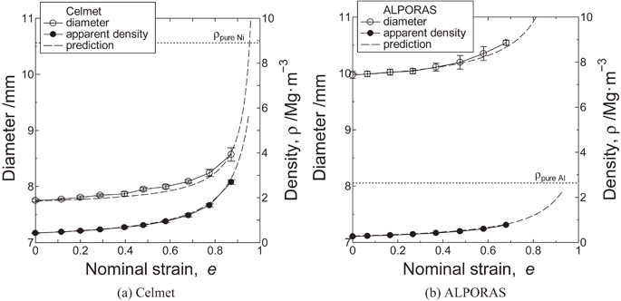
Fig. 5 Prediction and experimental results of changes in diameter and bulk density for (a) Celmet and (b) ALPORAS.
Metallic foams have cellular structure that is composed of a solid metal and a large volume fraction of pores. Metallic foams are divided into (a) open-cell and (b) closed-cell foams by pore structure. Open-cell foam has skeleton structure with open pores, while closed-cell foam is composed of gas-filled pores which are sealed each other. There are many possible applications of metallic foams ranging from construction, sound and heat insulation, energy absorption by advantages in lightweight and large surface area. However, industrial applications as structural materials are still limited due to low specific strength and difficulties in cutting1,2) and joining.3) Therefore manufacturing mechanical components with desired shape by metal forming is important.4) Although it is demanded to predict deformation behavior by numerical analysis, it is not easy because of large volume change in the processes.5)
Deformation behavior of metallic foams was often investigated by compression tests.6–8) Mukherjee et al.6) reported that the lateral constraint leads to strain hardening by formation of cell crush bands. Kadkhodapour et al.7) investigated the effect of relative density, cell shape and cell size of closed-cell foam on the mechanical properties. Saadatfar et al.8) investigated morphological/geometrical characteristics of cell collapse and strain localization in closed-cell aluminum foams by interrupted constrained uniaxial compression. They reported that the stress slightly increases with densification by pore closure, while the foam is deformed by shear banding by local cell collapse until heavy deformation.
By the way, most plasticity theories, e.g., von Mises, have been developed based on the assumption of the volume constancy. However metallic foams show large changes in volume and density with plastic deformation. Therefore, constitutive equation with consideration of compressibility is required. Deshpande et al.9) introduced plastic Poisson’s ratio and proposed the yield criteria of open and closed-cell type aluminum foam as a function of relative density and hydrostatic stress. Fang et al.10) performed numerical crushing simulation of foam-filled columns with change in plastic Poisson’s ratio. On the other hand, Shima et al.11) proposed the yield criterion of powder-sintered materials as a function of relative density and hydrostatic stress. Yoshimura et al.12) used Oyane’s yield criterion for prediction of the deformation of closed-cell aluminum foam. After obtaining material constants a and m in Oyane’s criterion experimentally, stress-strain curve in uniaxial compression was predicted. In their studies, however, change in density during forming have not been fully considered because of the change itself is not large.
For application to bulk metal forming, consideration of density change is necessary due to a large amount of change in density during the processes. Tsuruoka et al.13) investigated deformation behavior of open-cell, closed-cell foams and lotus metals in cold rolling. They used elongation efficiency which is the ratio of the longitudinal strain and the thickness strain to distinguish volume change in the bulk deformation. They reported that the elongation efficiency is a simple function of porosity regardless of pore structure. It seems to be very useful if same constants can be used for different porous materials and deformation processes.
In previous study, Kim et al.14,15) performed the repeated compression tests of closed-cell type aluminum foam (ALPORAS) and open-cell type nickel foam (Celmet). It is reported that the diameter change of metallic foams with high porosity is negligible until the particular strain of 0.4 which is close to the end of plateau region. A simple equation to estimate density was proposed under assumption of no diameter change. On the other hand the diameter change is not negligible after the plateau region so that it is not easy to predict the behavior.
In this study, the deformation behavior of the two metallic foams reported in the previous studies14,15) was analyzed to determine the material constants in Oyane’s criterion and the associated flow rule. Porosity and dimensional change of the two foams in uniaxial compression were successfully reproduced with the determined constants. In addition, obtained constants are compared with those in literature. It is supposed that deformation behaviors of metallic foams can be predicted with the constitutive equations and the material constants.
Experimental results of repeated compression tests of open-cell type nickel foam (Celmet® by Sumitomo Electric Industries Ltd.) and closed-cell type aluminum foam (ALPORAS® by Shinko Wire Company Ltd.) in the references14,15) were analyzed in this study. The specifications of the used specimens were shown in Table 1. The bulk density was determined by the measured weight and the apparent volume. The porosity, p was calculated using the bulk density ρbulk and the solid reference density ρreference.
| \begin{equation} p = 1 - (\rho_{\text{bulk}}/\rho_{\text{reference}}) \end{equation} | (1) |
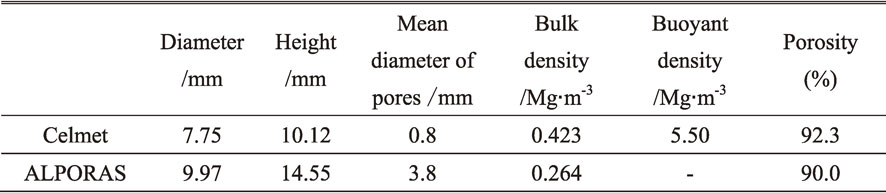
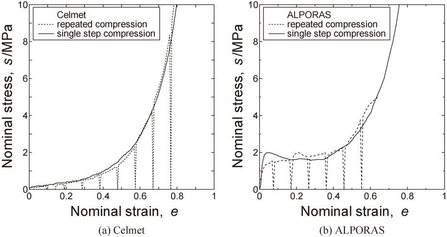
For the reference density, the buoyant density was used for Celmet, while the density of commercial aluminum (2.636 Mg/m3) was used for ALPORAS. ‘Buoyant density’ is the density measured by the Archimedes method. For the open-cell foam, the buoyant density and the real density are not same due to micro pores in ligaments. The compression was interrupted at every 10% of nominal reduction from the initial height, then the diameter, the height of the billet and the bulk density were measured under unloaded condition. Single-step compression test was also carried out for comparison.
Figure 1 shows typical nominal stress-strain curves of Celmet and ALPORAS in single-step and repeated compression.14,15) Nominal stress s and nominal strain e were defined as,
| \begin{equation} s = F/A_{0} \end{equation} | (2) |
| \begin{equation} e = (h_{0} - h)/h_{0} \end{equation} | (3) |
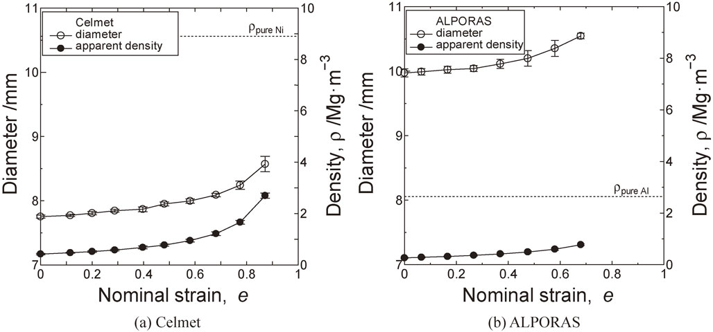
Changes in diameter and bulk density of Celmet and ALPORAS in the repeated compression were shown in Fig. 2. Error bars show that standard deviations among the nine measurement values (three specimens × three measurements). Changes in bulk densities of the two metallic foams show similar trend with their diameter change. Bulk density of Celmet increases linearly from 0.423 Mg/m3 to 0.681 Mg/m3 with little increase in diameter (7.75 mm to 7.87 mm) until the nominal strain of 0.4, then the bulk density increases to 2.69 Mg/m3 with increase in diameter to 8.57 mm. ALPORAS also shows similar change in density with Celmet although initial density and diameter are different. The bulk density and the diameter gradually increase until the nominal strain of 0.4 (bulk density: 0.264 Mg/m3 to 0.417 Mg/m3, diameter: 9.97 mm to 10.11 mm). Above the strain of e = 0.4, the density and the diameter apparently increase to 0.772 Mg/m3 and 10.55 mm, respectively.
Changes in density or porosity during the compression should be considered precisely together with diameter change. In the uniaxial compression of the compressible materials, metal flow in the radial direction competes with the volume change. To investigate how much strain in height εz turns into radial strain εr and peripheral strain εθ and volumetric strain εV, strains at the end of the i-th step of the compression were calculated from the dimensions as follows,
| \begin{equation} \varepsilon_{r}{}^{i} = \varepsilon_{\theta}{}^{i} = \ln\frac{r^{i}}{r_{0}},\quad\varepsilon_{z}{}^{i} = \ln\frac{h^{i}}{h_{0}} \end{equation} | (4) |
| \begin{equation} \varepsilon_{V}{}^{i} = \ln \frac{V^{i}}{V_{0}} = 2\ln\left(\frac{r^{i}}{r_{0}}\right) + \ln\left(\frac{h^{i}}{h_{0}}\right) = 2\varepsilon_{r}{}^{i} + \varepsilon_{z}{}^{i} \end{equation} | (5) |
Figure 3 shows experimental changes in volumetric strain εVi and radial strain εri against height strain εzi. In case of the nonporous metal, the volumetric strain should be zero during compression due to the volume constancy. However, volumetric strain changes greatly in the metallic foams. In case without diameter change (dashed line in Fig. 3), radial strain εr = 0, εV = εz. When εz > −1, the radial strain is negligible. The experimental volumetric strain is close to that under assumption of no diameter change. It means that the height strain εz mostly turns into volumetric strain εV when εz > −1, while radial strain becomes not negligible when εz < −1.
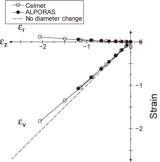
Experimental changes in volumetric and radial strain by height strain during repeated compression.
In order to express the above-mentioned change in dimensions as well as density in the compression test, the yield criterion for powder-sintered materials proposed by Shima et al.11) was used. The criterion is described by eq. (6),
| \begin{align} \bar{\sigma}& = \frac{1}{\varphi^{n}}\Bigg[\frac{1}{2}\left\{(\sigma_{1} - \sigma_{2})^{2} + (\sigma_{2} - \sigma_{3})^{2} + (\sigma_{3} - \sigma_{1})^{2}\right\} \\ &\quad + \left(\frac{\sigma_{\text{m}}}{f}\right)^{2}\Bigg]^{1/2} \end{align} | (6a) |
| \begin{equation} f = \frac{1}{a(1 - \varphi)^{m}} \end{equation} | (6b) |
If the associated flow rule $( \text{d}\varepsilon _{ij} = \text{d}\lambda \frac{\partial \bar{\sigma }}{\partial \sigma _{ij}} )$ is assumed, the principal plastic strain increments, dε1, dε2 and dε3 are derived by partial differentiation of $\bar{\sigma }$ with regarding to σ1, σ2 and σ3,
| \begin{align} &\text{d}\varepsilon_{1} = \frac{3}{2}\frac{1}{\varphi^{2n - 1}}\frac{\overline{\text{d}\varepsilon}}{\bar{\sigma}}\left\{\sigma_{1} - \left(1 - \frac{2}{9f^{2}}\right)\sigma_{\text{m}}\right\}\\ &\text{d}\varepsilon_{2} = \frac{3}{2}\frac{1}{\varphi^{2n - 1}}\frac{\overline{\text{d}\varepsilon}}{\bar{\sigma}}\left\{\sigma_{2} - \left(1 - \frac{2}{9f^{2}}\right)\sigma_{\text{m}}\right\}\\ &\text{d}\varepsilon_{3} = \frac{3}{2}\frac{1}{\varphi^{2n - 1}}\frac{\overline{\text{d}\varepsilon}}{\bar{\sigma}}\left\{\sigma_{3} - \left(1 - \frac{2}{9f^{2}}\right)\sigma_{\text{m}}\right\} \end{align} | (7) |
| \begin{align} \overline{\text{d}\varepsilon}& = \varphi^{n - 1}\biggl[\frac{2}{9}\{(\text{d}\varepsilon_{1} - \text{d}\varepsilon_{2})^{2} + (\text{d}\varepsilon_{2} - \text{d}\varepsilon_{3})^{2}\\ &\quad + (\text{d}\varepsilon_{3} - \text{d}\varepsilon_{1})^{2}\} + (f\text{d}\varepsilon_{V})^{2}\biggr]^{1/2} \end{align} | (8) |
| \begin{equation} \sigma_{\text{m}} = \frac{\sigma_{r} + \sigma_{\theta} + \sigma_{z}}{3} = \frac{\sigma_{z}}{3} \end{equation} | (9) |
| \begin{equation} \text{d}\varepsilon_{V} = \text{d}\varepsilon_{r} + \text{d}\varepsilon_{\theta} + \text{d}\varepsilon_{z} = 2\text{d}\varepsilon_{r} + \text{d}\varepsilon_{z} \end{equation} | (10) |
| \begin{equation} \text{d}\varepsilon_{r} = \text{d}\varepsilon_{\theta} = \frac{3}{2}\frac{1}{\varphi^{2n-1}}\frac{\overline{\text{d}\varepsilon}}{\bar{\sigma}}\left\{0 - \left(1 - \frac{2}{9f^{2}}\right)\frac{\sigma_{z}}{3}\right\} \end{equation} | (11a) |
| \begin{equation} \text{d}\varepsilon_{z} = \frac{3}{2}\frac{1}{\varphi^{2n-1}}\frac{\overline{\text{d}\varepsilon}}{\bar{\sigma}}\left\{\sigma_{z} - \left(1 - \frac{2}{9f^{2}}\right)\frac{\sigma_{z}}{3}\right\} \end{equation} | (11b) |
| \begin{equation} \frac{\text{d}\varepsilon_{r}}{\text{d}\varepsilon_{z}} = \cfrac{-\biggl(1 - \cfrac{2}{9f^{2}}\biggr)}{2\biggl(1 + \cfrac{1}{9f^{2}}\biggr)} = \cfrac{1 - \cfrac{9f^{2}}{2}}{1 + 9f^{2}} = \frac{2 - 9f^{2}}{2 + 18f^{2}} \end{equation} | (12a) |
| \begin{equation} \frac{\text{d}\varepsilon_{V}}{\text{d}\varepsilon_{z}} = \frac{2\text{d}\varepsilon_{r} + d\varepsilon_{z}}{\text{d}\varepsilon_{z}} = \cfrac{\cfrac{1}{3f^{2}}}{1 + \cfrac{1}{9f^{2}}} = \frac{3}{9f^{2} + 1} \end{equation} | (12b) |
The above equations are applied to the repeated compression test. The height strain and the height strain increment was calculated as $\varepsilon _{z}{}^{i} = \ln \frac{h^{i}}{h_{0}}$, $\Delta \varepsilon _{z}{}^{i} = \ln \frac{h_{i}}{h_{i - 1}}$. The radial and the volumetric strain increment were predicted by eq. (12) as,
| \begin{equation} \Delta\varepsilon_{r} = \Delta\varepsilon_{\theta} = \Delta\varepsilon_{z} \times \cfrac{1 - \cfrac{9f^{2}}{2}}{1 + 9f^{2}} = \Delta\varepsilon_{z} \times \frac{2 - 9f^{2}}{2 + 18f^{2}} \end{equation} | (13a) |
| \begin{equation} \Delta\varepsilon_{V} = \Delta\varepsilon_{z} \times \frac{3}{1 + 9f^{2}} \end{equation} | (13b) |
| \begin{align} \Delta\varepsilon_{V}{}^{i} &= \ln(V_{i}/V_{i - 1}) = \ln\left(\frac{1 - p_{i - 1}}{1 - p_{i}}\right)\\ &= \ln (1 - p_{i - 1}) - \ln(1 - p_{i}) = \ln\rho_{i - 1} - \ln\rho_{i} \end{align} | (14) |
| \begin{equation} \ln(1 - p_{i}) = \ln(1 - p_{i - 1}) - \Delta\varepsilon_{V}{}^{i} \end{equation} | (15) |
| \begin{equation} p = 1 - \exp\{\ln(1 - p_{0}) - \varepsilon_{V}\} \end{equation} | (16a) |
| \begin{equation} \varphi = 1 - p \end{equation} | (16b) |
Experimental and prediction results of the incremental strain ratios were shown as a function of porosity in Fig. 4. As porosity decreases, strain ratio |Δεr/Δεz| increases with an increase in diameter. While, strain ratio |ΔεV/Δεz| decreases with decreasing porosity.
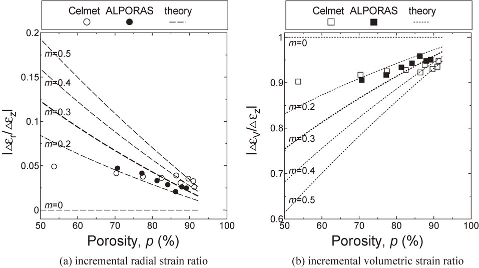
Experimental and prediction results of the incremental (a) radial and (b) volumetric strain ratios as a function of porosity. The prediction is estimated with a = 2.12 and various material constants of m by eq. (12).
In order to determine material constants a and m, experimental results are compared with theoretical curves with various material constants. a and m are material constants, which are independent from porosity or relative density.11) Tsuruoka et al.13) performed cold rolling and calculated the elongation efficiency. They determined $a = 3/\sqrt{2} = 2.12$ based on the insight if φ → 0 (or p → 1), that means the material is nearly air, the elongation efficiency should be close to zero. Same value can be derived if no radial strain increment is assumed for uniaxial compression of a dilute porous material (φ → 0). Among the prediction with various constants of m, the prediction for 0.3 of m shows good agreement with experimental results. It is notable that the value (m = 0.3) is same as Tsuruoka obtained by cold rolling as seen in Fig. 4. Therefore, the material constants for metallic foams is obtained (a = 2.12, m = 0.3).
Inversely changes in diameter and density are predicted with the obtained material constants. Radial strain was expressed by
| \begin{equation} \varepsilon_{r} = \varepsilon_{1} = \ln(d/d_{0}) = \ln d - \ln d_{0} \end{equation} | (17) |
| \begin{align} &\ln d = \varepsilon_{1} + \ln d_{0}\\ &d = \exp(\varepsilon_{1} + \ln d_{0}) = \exp\left(\sum\nolimits_{i = 1}^{n}\Delta\varepsilon_{r} + \ln d_{0}\right) \end{align} | (18) |
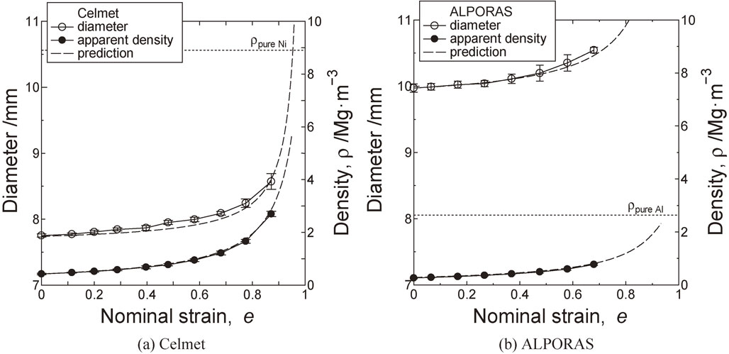
Prediction and experimental results of changes in diameter and bulk density for (a) Celmet and (b) ALPORAS.
Material constants of Oyane’s equation used in other studies were compared in Table 2. The original Oyane’s material constants, a = 2.5 and m = 0.5,11) covers a little range of relative density from 0.69 to 0.73 because they were used for sintered powders. When material constants of a and m increases, f in eq. (6b) decreases. It means yielding dependence on hydrostatic stress increases.
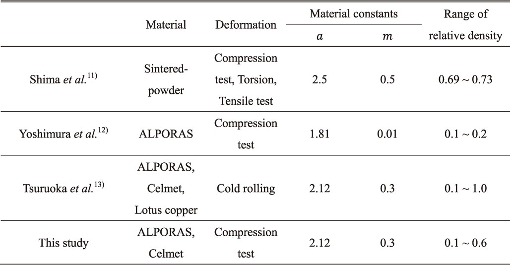
On the other hand, Yoshimura obtained a = 1.81 and m = 0.01 for ALPORAS12) under a narrow range of low relative density from 0.1 to 0.2. Tsuruoka et al.13) investigated the deformation behavior under a wide range of porosity in cold rolling process. In this study, it was found that the same constants as Tsuruoka’s constants are valid for uniaxial compression in a wide range of relative density from 0.1 to 0.6.
Based on the comparison, it is found that prediction of deformation of porous metals until large deformation with large change in density is possible if we use Tsuruoka’s constants. It is supposed that prediction of deformation and density will be practical with finite element (FE) analysis using the above-mentioned constitutive equation and material constants.
Yield function of compressible sintered material (Oyane’s criterion) and the associated flow rule were applied to express the deformation behavior of two metallic foams [open-cell type nickel foam (Celmet) and closed-cell type aluminum foam (ALPORAS)] in uniaxial compression test. The obtained remarks are summarized as follows.