Abstract
The effect of Zr addition on the corrosion behavior of an extruded Mg-10Gd-1Zn alloy (GZ101) in 3.5 mass% NaCl solution was investigated by electrochemical and immersion tests in 3.5% NaCl solution. The addition of 1 mass% Zr to GZ101 (to afford GZ101-1Zr) decreased the fraction of 14H (number of stacking layers and H-Hexahedral structure) and lamellar long period stacking ordered (LPSO) phases across the α-Mg matrix and increased the fraction of the X-phase (Mg12GdZn) formed at grain boundaries. Extruded GZ101-1Zr exhibited a significantly smaller corrosion rate than extruded GZ101 (0.13 vs. 2.11 mm∙year−1) due to containing less 14H/lamellar LPSO phases (detrimental to corrosion resistance) and featuring a noble $\{10\bar{1}0\}$ prismatic texture in the extrusion direction.
1. Introduction
The use of lightweight structural materials provides a solution to a number of environmental problems, improves the energy efficiency of certain processes (e.g., of those employed in the fabrication of automobile parts) and therefore has attracted increased attention. For example, the superior mechanical properties of magnesium alloys have made them a popular research subject,1) despite their applications still being limited by poor high-temperature performance and corrosion resistance.2–4)
The corrosion resistance and mechanical properties of magnesium alloys have been widely investigated.4–6) Srinivasan et al. showed that the addition of rare earth (RE) elements improves the strength and corrosion resistance of the above alloys.4) Moreover, such property improvement is also greatly affected by the presence of long periodic stacking order (LPSO) structures observed in Zn-containing Mg-RE alloys.5,6)
In addition, the corrosion resistance of wrought Mg alloys is also significantly influenced by their texture, since it affects the atomic packing density and crystallographic anisotropy in the hexagonal close-packed (HCP) structure of these alloys.7,8) The surface normal direction of the plate has a predominant basal texture developed through the rolling process, which shows a more stable surface than the cross-section surface in the NaCl aqueous solution environment of the previously reported.7)
In particular, the effect of secondary (e.g., I-, W-, and X-) phases on the microstructure and mechanical properties of ternary Mg-Gd-Zn alloys has been extensively investigated.9,10) However, studies dealing with the corrosion resistance of such alloys are still scarce. Zr doping is a very effective method of improving tensile elongation via grain refinement. In the case of Al-free alloys, α-Mg nuclei form on the surface of Zr nuclei due to the role of nuclei in casting and grain refinement is caused.9,11) However, the optimization of Zr content in Mg-RE alloys is still underexplored.12,13)
Herein, we describe how the corrosion resistance of Mg alloys can be improved by Zr addition and extrusion, by subjecting extruded samples placed in 3.5 mass% aqueous NaCl to electrochemical corrosion and immersion tests and further probing their properties by field emission scanning electron microscopy (FE-SEM) coupled with energy-dispersive X-ray scatter (EDS) and electron backscatter diffraction (EBSD) analyses.
2. Experimental Procedure
Ingots with a nominal composition of Mg-10Gd-1Zn-xZr (here and subsequently, the above numbers/notation correspond to mass%; x = 0 and 1.0) were prepared by adding Mg-39Gd and Mg-33.3Zr master alloys to molten Mg (99.9 mass%) contained in a BN-coated steel crucible held in an electrical furnace under a dynamic protective gas (SF6 + CO2) atmosphere to prevent Mg oxidation. The melt was held at 1023 K for 40 min and stirred for 1 min before casting into a BN-coated steel mold preheated to 473 K to produce billets (diameter = 42 mm, length = 135 mm). The above billets were homogenized at 783 K for 12 h and cooled by warm water at 353 K to afford “ST” samples, being subsequently subjected to hot extrusion at 703 K, a ram speed of 2.5 mm/s, and an extrusion ratio of 10:1 to afford “AE” samples. Samples with dimensions of 50 × 5 × 2 mm3 were used for the immersion test, with those utilized for the electrochemical corrosion test being about 50-mm-long with a diameter of 11 mm. Finally, the as-prepared samples were polished with SiC paper and rinsed with ethanol.
The microstructural analysis was performed by FE-SEM (JEOL, JSM-7001F) coupled with EDS and EBSD (EDAX-TSL, Digiview). The fractions of secondary phases were measured by analyzing (Image J 1.48) SEM images for at least five areas of each sample. Quantitative secondary phase EDS analysis was performed at different randomly selected locations, and the results were expressed as average with standard deviation.
The immersion test was performed in 3.5 mass% aqueous NaCl at 298 K, and the produced corrosion products were removed using a solution of CrO3 (200 g), AgNO3 (10 g), and Ba(NO3)2 (20 g) in deionized water (1000 mL). The corrosion rates were expressed in millimeters per year (mm∙year−1) was evaluated by measuring the weight change after immersion test.14) Electrochemical corrosion tests were carried out in 3.5 mass% aqueous NaCl at 298 K according to ASTM G 5.15) The test cell comprised a working electrode, a glass capillary probe connected to a saturated calomel reference electrode (SCE), and two graphite rod counter electrodes, and testing was conducted within a potential range of −2.0 to −1.0 V vs. SCE at a scan rate of 1 mV/s.
3. Results and Discussions
Figure 1 shows low- and high-magnification SEM images of ST samples. As shown in Figs. 1(a) and (c), the Mg-10Gd-1Zn (further referred to as GZ101) alloy comprised four phases, namely α-Mg, Mg5Gd, 14H LPSO (Yamasaki found that 14H-type LPSO phase formed in Mg97Zn1Gd2 (at%) alloy, who showed a stacking sequence of ABABABACBCBCBC with a period)16,17), and lamellar LPSO. However, the Mg-10Gd-1Zn-1Zr alloy (further referred to as GZ101-1Zr; Figs. 1(b) and (d)) was markedly different from GZ101. In particular, the addition of Zr decreased the contents of 14H LPSO (1.33 → 0.51 vol%), lamellar LPSO (3.8 → 1.83 vol%), and Mg5Gd (0.83 → 0.45 vol%) phases, increasing that of the X phase (2.6 → 3.86 vol%). Moreover, GZ101-1Zr exhibited an increased total secondary phase fraction (6 → 6.7 vol%) and contained a ZnZr phase formed at the center of α-Mg grains. The chemical compositions of all phases were in good agreement with those determined previously (Table 1).9,13,18)
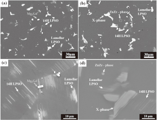
Table 1
Average chemical compositions of the intermetallic compounds formed on the experimental alloys by using SEM-EDS.
| Intermetallic compounds |
Chemical composition (at%) |
| Gd |
Zn |
Zr |
Mg |
| Mg5Gd |
17.8 |
- |
- |
Balance |
| 14H LPSO |
2.6 |
1.5 |
- |
Balance |
| Lamellar LPSO |
5.6 |
3.9 |
- |
Balance |
| X-phase |
10.8 |
7.0 |
- |
Balance |
| ZnZr |
1.9 |
0.4 |
0.4 |
Balance |
Table 2
Electrochemical corrosion parameters obtained from potentiodynamic polarization curves of the extruded alloys.
| Alloys |
icorr (µA/cm2) |
Ecorr (V) |
βc (mV/dacade) |
βa (mV/dacade) |
| GZ101 |
81.8 |
−1.57 |
254 |
88 |
| GZ101-1Zr |
4.2 |
−1.82 |
98 |
104 |
Figure 2 shows SEM images of AE samples, revealing that extrusion-induced microstructure deformation and recrystallization were observed for both alloys. Moreover, the fractions of 14 H (0.13 vol%) and lamellar (1.55 vol%) LPSO phases decreased in as-extruded GZ101, with as-extruded GZ101-1Zr containing 0.51 vol% of the lamellar LPSO phase. Interestingly, the above phases were split into small particles aligned in the extrusion direction, whereas X-phase (3.8 vol%) particles were almost unaffected by extrusion, being only slightly elongated in the extrusion direction. Additionally, banded bulk β phase formation was also observed, as reported previously,19) with the total secondary phase fractions in as-extruded GZ101 and GZ101-1Zr equaling 9.8 and 11.5 vol%, respectively.
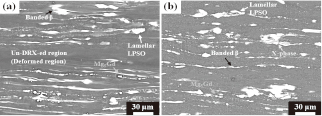
Figure 3 presents EBSD images and pole figures of extruded GZ101 and GZ101-1Zr, showing that dynamic recrystallization during extrusion resulted in the formation of recrystallized microstructures, which were more homogenously distributed and fine-grained in the case of extruded GZ101-1Zr (Figs. 3(c) and (d)). In addition, Figs. 3(e) and (f) show that the average grain size of extruded GZ101 (~24.58 μm) was smaller than that of extruded GZ101-1Zr (~70.32 μm). The (0001) basal and $(10\bar{1}0)$ prismatic pole figures indicate that the addition of 1 mass% Zr to GZ101 decreased the maximum basal pole intensity due to inducing dynamic recrystallization, but deformed grain distribution became homogeneous with small size to the direction of extrusion (Figs. 3(g)–(j)). Based on the above results, the addition of Zr favored the development of a $\{10\bar{1}0\}$ prismatic texture in the extrusion direction and resulted in the basal plane being inclined to the sample normal direction of the extruded alloy.
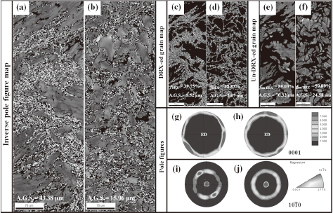
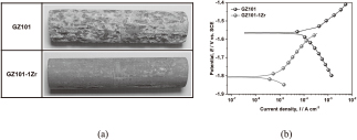
Figure 4 shows the corrosion morphologies obtained after the seven-day immersion test of extruded alloys and their potentiodynamic polarization curves in 3.5 mass% aqueous NaCl at 298 K. As shown in Fig. 4(a), extruded GZ101-1Zr featured a more stable corrosion morphology than extruded GZ101, additionally exhibiting a significantly decreased corrosion rate (2.11 → 0.13 mm∙year−1). However, the corrosion rates of GZ101 and GZ101-1Zr calculated from potentiodynamic polarization curves equaled 0.67 and 0.15 mm∙year−1, respectively, indicating the significant effect of analysis conditions such as test time and exposure area. In addition, a much higher corrosion current density was observed for extruded GZ101-1Zr (Fig. 4(b)). The electrochemical corrosion parameters are summarized in Table 2.
As reported previously,18,20) the addition of Zr to Mg-Gd-Zn alloys results in the formation of a ZnZr phase, and hinders the formation of LPSO structure due to causing Zn consumption. Therefore, the formation of 14 H and lamellar LPSO phases in GZ101-1Zr was suppressed, as shown in Figs. 1 (c) and (d). Furthermore, the above addition did not induce significant shape changes for the X-phase formed at grain boundaries in GZ101-1Zr, whereas 14 H and lamellar LPSO phases were broken up into small particles in the extruded GZ101 sample. Therefore, a stronger PSN effect was observed for the X-phase than for 14 H and lamellar LPSO phases, resulting in microstructure recrystallization (Figs. 2 (a) and (b)).
The obtained results indicated that the addition of Zr resulted in significantly microstructure change and increased corrosion resistance. Moreover, EBSD analysis indicated that Zr addition not only improved the distribution of small deformed grains but also decreased the size of recrystallized grains formed after extrusion in GZ101-1Zr (Figs. 3 (a)–(f)). The smaller recrystallized grains had a random texture, whereas the deformed grains had a strong in $\{10\bar{1}0\}$ prismatic texture in the extrusion direction, as shown in Figs. 3 (g) and (h). Overall, the corrosion resistance of extruded alloys was improved by Zr addition, in line with the well-known fact that phase and texture microstructural features are closely related to the corrosion behavior of Mg alloys.7,8,21)
Extruded GZ101-1Zr exhibited the more stable corrosion morphology than GZ101 and featured a significantly smaller corrosion current density (Figs. 4 (a) and (b)). These results were attributed to the decreased fraction of 14H and lamellar phases (which had a continuous net-like shape in Mg matrix grains and deteriorated corrosion resistance due to promoting the generation of micro-galvanic sites) in the former alloy.21)
From the viewpoint of galvanic couple formation, the above behavior was expected to suppress the partial cathodic reaction and reduce corrosion current density during the corrosion process. However, X-phase formation at alloy grain boundaries enhanced corrosion resistance due to acting as a corrosion barrier.22) Furthermore, in extruded GZ101-1Zr, almost all grains exhibited a $\{10\bar{1}0\}$ prismatic texture in the extrusion direction and featured a homogeneous size distribution. In general, it is known that the corrosion resistance of the basal plane superior wrought magnesium alloys due to the packing density of the atoms in the crystallographic anisotropy in the HCP structure.7,8) Also, it can be seen that the reduced corrosion rate influenced by the grains with (0002) preferential orientation with newly deformed $\{10\bar{1}0\}$ prismatic texture to the ED during extrusion, due to the more difficult to corrode away, since the corrosion current density effectively decreased of the Mg matrix grain when exposed an aqueous solution.7)
4. Conclusions
Herein, we investigated the corrosion resistance of extruded Zr-doped (GZ101-1Zr) and non-doped (GZ101) Mg alloys in 3.5 mass% NaCl solution, revealing that Zr doping decreased the fraction of 14H and lamellar LPSO phases. Additionally, extruded GZ101-1Zr exhibited a much smaller corrosion rate than extruded GZ101 (0.13 vs. 2.11 mm∙year−1) due to containing smaller amounts of 14H and lamellar LPSO phases (detrimental to corrosion resistance) and exhibiting a $\{10\bar{1}0\}$ prismatic texture in the extrusion direction. The above changes led to the basal plane being inclined to the sample normal direction (surface) and significantly decreased the corrosion rate of extruded GZ101-1Zr in aqueous NaCl solutions.
Acknowledgements
This study was financially supported by the Important Defense Materials Technology Development project funded by the Korea Ministry of Industrial, Trade and Energy (Project No. NRF 10043821) Korea Government.
REFERENCES
- 1) J. Hirsch and T. Al-Samman: Acta Mater. 61 (2013) 818–843. 10.1016/j.actamat.2012.10.044
- 2) G.Y. Yuan, Z.L. Liu, Q.D. Wang and W.J. Ding: Mater. Lett. 56 (2002) 53–58. 10.1016/S0167-577X(02)00417-2
- 3) M.O. Pekguleryuz and A.A. Kaya: Adv. Eng. Mater. 5 (2003) 866–878. 10.1002/adem.200300403
- 4) A. Srinivasan, Y. Huang, C.L. Mendis, H. Dieringa, C. Blawert, K.U. Kainer and N. Hort: Mater. Sci. Forum 765 (2013) 28–32. 10.4028/www.scientific.net/MSF.765.28
- 5) M. Yamasaki, M. Sasaki, M. Nishijima, K. Hiraga and Y. Kawamura: Acta Mater. 55 (2007) 6798–6805. 10.1016/j.actamat.2007.08.033
- 6) T. Honma, T. Ohkubo, S. Kamado and K. Hono: Acta Mater. 55 (2007) 4137–4150. 10.1016/j.actamat.2007.02.036
- 7) G. Song (Ed.), Corrosion of Magnesium Alloys, WP Publishing (2011) 46–51.
- 8) M. Liu, D. Qiu, M.-C. Jhao, G. Song and A. Atrens: Scr. Mater. 58 (2008) 421–424. 10.1016/j.scriptamat.2007.10.027
- 9) A. Srinivasan, Y. Huang, C.L. Mendis, C. Blawert, K.U. Kainer and N. Hort: Mater. Sci. Eng. A 595 (2014) 224–234. 10.1016/j.msea.2013.12.016
- 10) K.R. Athul, A. Srinivasan, U.T. Subramonia Pillai and B. Chandrasekhara Pai: Mater. Sci. Forum 830 (2015) 631–634.
- 11) C. Wang, M. Sun, F. Zheng, L. Peng and W. Ding: J. Mag. and Alloys 2 (2014) 239–244. 10.1016/j.jma.2014.09.001
- 12) M. Sun, G. Wu, W. Wang and W. Ding: Mater. Sci. Eng. A 523 (2009) 145–151. 10.1016/j.msea.2009.06.002
- 13) M. Yang, H. Li, R. Cheng, F. Pan and H. Hu: Mater. Sci. Eng. A 545 (2012) 201–208. 10.1016/j.msea.2012.03.035
- 14) M. Yuasa, X. Huang, K. Suzuki, M. Mabuchi and Y. Chino: Mater. Trans. 55 (2014) 1202–1207. 10.2320/matertrans.MC201403
- 15) Annual Book of ASTM Standards, ASTM G5.
- 16) M. Yamasaki, T. Anan, S. Yoshimoto and Y. Kawamura: Scr. Mater. 53 (2005) 799–803. 10.1016/j.scriptamat.2005.06.006
- 17) M. Yamasaki, M. Sasaki, M. Nishijima, K. Hiraga and Y. Kawamura: Acta Mater. 55 (2007) 6798–6805. 10.1016/j.actamat.2007.08.033
- 18) J.H. Li, J. Barrirero, G. Sha, H. Aboulfadl, F. Mücklich and P. Schumacher: Acta Mater. 108 (2016) 207–218. 10.1016/j.actamat.2016.01.053
- 19) J.G. Jung, S.H. Park, H. Yu, Y.M. Kim, Y.-K. Lee and B.S. You: Scr. Mater. 93 (2014) 8–11. 10.1016/j.scriptamat.2014.08.017
- 20) W. Rong, Y. Zhang, Y. Wu, M. Sun, J. Chen, Y. Wang, J. Han, L. Peng and H. Ding: J. Alloy. Compd. 692 (2017) 805–816. 10.1016/j.jallcom.2016.09.068
- 21) A. Srinivasan, C. Blawert, Y. Huang, C.L. Mendis, K.U. Kainer and N. Hort: J. Mag. And Alloys 2 (2014) 245–256. 10.1016/j.jma.2014.08.002
- 22) J. Zhang, J. Xu, W. Cheng, C. Chen and J. Kang: J. Mater. Sci. Technol. 28 (2012) 1157–1162. 10.1016/S1005-0302(12)60186-8
