Influence of Metallic Foam Inter-Layers on the Mechanical Properties of Self-Piercing Riveted Sandwich Joints
2018 年 59 巻 9 号 p. 1440-1445

詳細
2018 年 59 巻 9 号 p. 1440-1445
The influence of different metallic foam inter-layers on the mechanical properties of self-piercing riveted (SPR) sandwich joints is investigated in this paper. Comparing with the homogeneous sheet of AA5052, the copper, nickel, iron-nickel foams are added in the joints as inter-layers. The tensile-shear test, SEM and EDS experiments are employed to discuss the mechanical properties of SPR sandwich joints. The results indicate that the addition of metallic foam inter-layers can effectively affect the mechanical lock inside of SPR sandwich joints. The SPR sandwich joint with iron-nickel foam inter-layers exhibits the highest peak load. The SPR sandwich joint with nickel foam inter-layers exhibits the maximum failure displacement and the energy absorption value.
Due to the huge pressure of energy shortage and environmental pollution caused by various industrial fields, lightweight structure has become one of the most important means to improve the competitiveness of the products. Moreover, in recent years, new light sheet materials are widely used in aerospace, automobile manufacturing and other industrial fields. Friction stir welding,1) laser welding,2) self piercing riveting (SPR),3–5) clinching,6–8) structural bonding9–11) and other advanced light alloy sheet connection technology are widely used.
The SPR technology belongs to the domain of rapid cold forming machinery technology. The principle is to realize the effective connection between sheets relied on the mechanical lock inside, which is formed by the plastic deformation and the spring-back among the upper and lower sheets and rivets during the riveting process. AA5052 aluminum alloy is one of the antirust aluminum which is used the most widely, that characteristic in light weight and well-processing performance. However, it cannot be processed through the ordinary spot welding. The most suitable processing method to join AA5052 sheets is SPR. It is well known that various investigations have been done in SPR of AA5052 sheets.12,13) Researches also center on influence of differing thickness sheets on the mechanical properties of SPR joints.14)
Metal foam is a new structural and functional materials, it is often used as an internal structure forming the sandwich structure, which is characterized in that the base metal is distributed in a large number of holes.15) The synthetic board has better mechanical and thermal properties.16,17) Although the sandwich structure containing the metal foam has been applied extraordinary widely, the research only involves traditional riveting, bonding and screw nut connecting etc. Related references about the SPR sandwich joints have not been reported yet.
In this paper, the copper foam, nickel foam, and iron-nickel alloy foam inter-layers are added inside the AA5052 basis SPR joints aimed to improve the shock absorption performance and the acoustical behavior. The tensile-shear tests, scanning electron microscopy (SEM) tests and energy dispersive X-ray (EDX) experiments are employed to discuss the mechanical properties of the SPR sandwich joints.
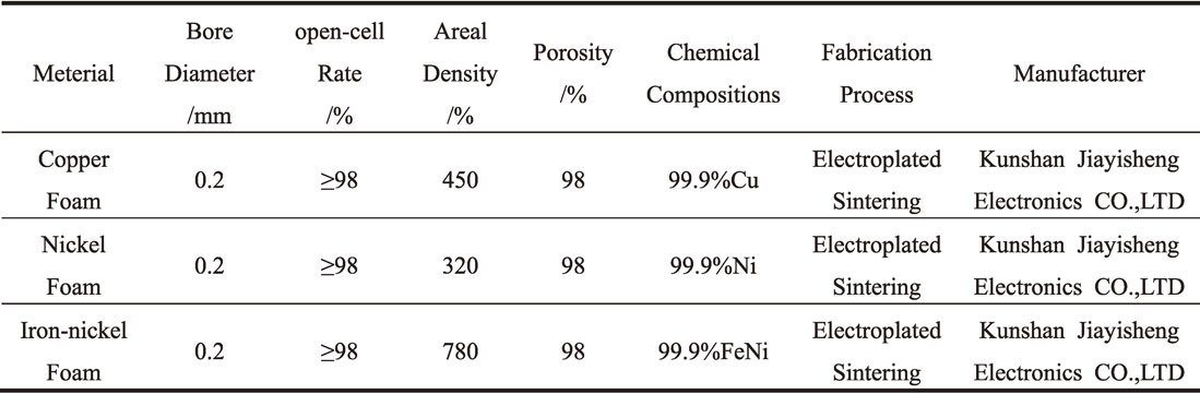
The mechanical properties of the AA5052 aluminum alloy used in the test are shown in Table 1 that are experimented in MTS landmark100 electro-hydraulic servo test machine. The material parameters of metallic foams are shown in Table 2. The process is based on the tensile test method of GB/T228-2002 metal material. The distance between extensometer and gauge is 20 mm.

SPR riveting equipment modeled RIVSETVARIO-FC (MTF) is manufactured in Böllhoff from Germany. After the riveting experiments, the riveting parameters have been confirmed, that is, the pre-pressing pressure is 5 MPa, the piercing pressure is 15 MPa, the shaping pressure is 10 MPa, and the punch travel distance is 132.46 mm. These parameter will be used in four groups of joints. The hardness of rivets used in this paper is H4, and the shape and size of the rivet are shown in Fig. 1(a). The geometrical shape and dimensions of the sample are shown in Fig. 1(b). The size of metallic foam inter-layer is 20 mm * 20 mm, and the thickness is 1 mm. Four groups of single lap joint specimens with the same thickness are prepared according to the above dimensions, each of which has 12 specimens. Four groups of joints are named respectively AO, AC, AN, AF. The optimum joint section of four groups of specimens is shown in Fig. 2.

(a) Illustration of the rivet (b) Illustration of the tensile shear test specimen.

Cross-sections of the optimum joints.
The tensile-shear tests were conducted on the Landmark 100 electro-hydraulic servo test machine which is manufactured by MTS company in the United States. Each group was tested with 12 specimens. Since there is a certain thickness difference between the upper plate and the lower plate, it is possible to produce the torque by clamping the specimen directly. Uniform thickness spacers are laid on both sides of the plate to decrease the torque. The tensile speed is 5 mm/min. The load-displacement curves of the SPR sandwich joints obtained in the tests are shown in Fig. 3.

Load-displacement curves of the SPR joints.
In the riveting process, the same riveting parameters were used in four groups of joints. It can be seen from Fig. 2 that three evaluation indexes are labeled which named head height of the rivet, spread of the rivet and remaining bottom thickness of the rivet.
On account of the existent of metallic inter-layer, compared with AO group, remaining bottom thickness of the rivet of other groups gets thicker. Three different metallic foam inter-layers have different hardness. The nickel foam is softer than copper foam, and iron-nickel foam is much harder than copper foam. Under the same riveting parameters, remaining bottom thickness of AC joint is bigger than AN joint. As the spread of the rivet of AF joint gets lower obviously, so the remaining thickness of AF joint will be lower.
In the riveting process, with the rivet goes downward, the upper sheet is pierced firstly, and then the rivet is penetrated into the lower sheet accompanied by spreading the rivet feet. The spread of the rivet of AO joint is 0.72 mm, AC joint is 0.72 mm, AN joint is 0.67 mm, and AF joint is 0.59 mm. It verifies that softer inter-layers make the spread of the rivet bigger. Additional, AN group is a little lower than AC group, the reason is that nickel foam is so soft that impede the rivet less in transformation.
In general, the addition of metallic foam inter-layers affect the mechanical lock inside of SPR sandwich joints to some extent, and it can play a positive role in the forming quality of SPR sandwich joint.
4.2 Static failure load and displacementIn the tensile-shear test, the distribution of test results obeys the normal distribution approximately. This is a typical small sample data. Therefore, the T distribution is selected in Matlab2014B to validate the test data, and the peak load and the maximum failure displacement are tested. The confidence of the sample is 95%, and the test result is shown in Table 3. As can be seen from the table, the peak load and the maximum failure displacement of three sets of joints meet the requirements of their confidence interval, and the test results are valid.

The static failure load of AO group joints is 3601.8 N, which is between the AN group (3365.6 N) and the AF group (3895.7 N). AC group (3297.7 N) is lower than AN group. The influence of different metallic foam inter-layers on SPR sandwich joints is mainly composed of two parts. Firstly, the addition of metallic foam inter-layers change the forming quality of SPR sandwich joints. Additional, in the tensile test, the metallic foam inter-layer plays a lubrication role between the rivet and the base board during the process of extrusion, which makes it smaller in the process of extrusion. As can be seen in Fig. 2, metallic foam exists in the interlocking area as a dense state.12) This proves that inter-layers will give an influence to the forming quality, hence affect the remaining bottom thickness and spread of the rivet. Additionally, AC and AN joints with dense-state metallic foam occupy fixed volume in the inter-lock area, and it will lubricate the joint, making it easier to failure. These factors affect the peak load collectively.
The maximum failure displacement of AO joint is 4.755 mm, greater than that of the AC joint (4.678 mm), larger than that of the AF joint (4.436 mm). The AN joint has the greatest failure displacement (5.201 mm). As the hardness of copper and nickel are lower than iron-nickel, the dense-state metallic foams of the AC and AN joints make lubricate influence to the joints at a greater extent. Meanwhile, the iron-nickel foam inter-layers give a positive influence to the SPR sandwich joints. On the other hand, the remaining bottom thickness of the AF joint is the minimum one, this indicates that the rivet of the AF joint penetrate the sheet material deepest, and finally lead to that the maximum failure displacement of the AF joint becomes the largest.
In general, the hardness of different metallic foam inter-layers affects forming quality of the joints, peak load and the maximum failure displacement. The peak load of the joints with iron-nickel foam will increase. The maximum failure displacement of the joints with nickel foam will increase. Joints with copper foam can effectively avoid the load decreasing severely during the tensile test.
4.3 Energy absorption performanceThe energy absorption value of the SPR sandwich joint reflects the shock absorption performance of the joint. In this paper, the energy absorption value of each joint is obtained by using MATLAB R2014b numerical method, and the accuracy is 0.001. According to Formula 1, the average energy absorption value of each group is calculated, and the function image, namely load and displacement curve, is plotted to detect whether the data is abnormal or not.
| \begin{align} S_{\text{i}}(X) &= M_{i}\frac{(X_{i+1}-X)^{3}}{6h_{i}}+M_{i+1}\frac{(X-X_{i})^{3}}{6h_{i}}\\ &\quad + \left(y_{i} - \frac{M_{i}h^{2}_{i}}{6}\right)\frac{X_{i+1}-X}{h_{i}} \\ &\quad+ \left(y_{i+1}-\frac{M_{i+1}h^{2}_{i}}{6}\right)\frac{X-X_{i}}{h_{i}} \end{align} | (1) |
| \begin{equation*} \mathrm{h}_{\text{i}} = X_{i+1}-X_{i} \end{equation*} |
| \begin{equation*} S''(X_{i}) = M_{i} \end{equation*} |
| \begin{equation*} S(X) = \sum S_{i}(X) \end{equation*} |
After running the MATLAB program, the energy absorption can be calculated. The energy absorption of AO group is 11.858 J, AC group is 9.757 J, AN group is 11.983 J, and AF group is 11.680 J. Visually, the energy absorption value of the joint is expressed as the area between the load displacement curve and the X axis, which is directly related to the maximum peak load and the failure displacement. On the whole, the energy absorption value of the test object after adding foam copper is reduced, but joints with nickel and iron-nickel foam inter-layers express larger energy absorption. The dense foam copper inter-layer affects the internal structure of the SPR sandwich joint, and the lubrication effect is the main reason for the decrease of energy absorption value during the rivet withdrawal. The nickel and iron-nickel foam in AN and AF groups effectively prevent the load drop and extend the tear distance between the rivet head and the upper plate. This is the main reason that the energy absorption value of the AN and AF joints are greater than that of the AO joints.
4.4 Microscopic failure mechanismFor analyzing the microscopic failure mechanisms of the SPR sandwich joints, SEM and EDS experiments were carried out to detect the representative fracture surfaces. The SEM and EDS images of the joints are shown in Fig. 4 and Fig. 5.

SEM and EDS images of the rivet. (a) SEM image of the rivet. (b) Magnified image marked by frame. (c) Point dimension. (d) Element contents of point 1. (e) Element contents of point 2. (f) Element contents of point 3. (g) Element contents of point 4.

SEM and EDS images of the failure part. (a) SEM image of the failure part. (b) Magnified image marked by frame. (c) Point dimension. (d) Element contents of point 1. (e) Element contents of point 2.
The microscopic structure graph and energy spectrum analysis are exhibited in Fig. 4, from which the striations can be evidently observed. From Fig. 4(c) to 4(g), element contents of four points labeled in graph 4(c) have been shown. From region 1 to region 4, pulling out process of the rivet is evidently investigated. The metallic foam inter-layers mainly exist in region 1 and region 3. SEM and EDS graphs of the failure part in upper sheet are displayed in Fig. 5. Region 1 investigates the element distribution of the base sheet. From Fig. 5(e), oxidized sheet and metallic foam can be observed clearly.
This study is supported by the National Natural Science Foundation of China (Grant No. 51565023, 51565022) and Major Program Foundation of the Education Department of Yunnan Province, China (Grant No. ZD201504).