Abstract
Al foam was press-formed utilizing a steel mesh die during the foaming of the precursor to shape the Al foam. The effects of the temperature of the precursor and the pressing velocity during press forming on the forming behavior of the obtained Al foam were investigated. It was found that Al foam was sufficiently softened above the liquidus temperature to conduct press forming. In contrast, press forming cannot be conducted below the liquidus temperature. The press forming of Al foam should be conducted after the Al foam has been sufficiently foamed above the liquidus temperature to obtain high-porosity Al foam. No extrusion of Al foam through the mesh openings occurred even when press forming was conducted above the liquidus temperature. The Al foam and steel mesh were easily separated. The mesh pattern was clearly observed on the surface of Al foams. There is little effect of conducting press forming on the pore structures of the obtained Al foams regardless of pressing velocity. Al foam with a triangular cross section having the same shape as the steel mesh die and a porosity of approximately 80% was obtained. The press-formed Al foam sufficiently filled the steel mesh die. Consequently, it was demonstrated that the press forming of Al foam after sufficient foaming is effective for fabricating Al foams with complex shapes.

1. Introduction
A near-net-shape manufacturing process for aluminum (Al) foam is a key technology for the application of Al foam in the transportation and construction material industries, in which lightweight materials are required.1,2) However, the shaping of Al foam by plastic deformation and cutting is relatively difficult owing to the thin walls of pores. The plastic deformation of Al foam easily causes the pores to collapse, which may result in its bending,3) and its forging.4) The cutting of Al foams easily causes the thin walls of pores to fold.5,6) This difficulty of shaping Al foam limits its wider application in various industrial fields.
A precursor foaming process has been developed to enable the manufacture of Al foams with desired pore structures.7) In this manufacturing process, a blowing agent powder distributed in solid Al called a “precursor” is first fabricated by a powder metallurgy route,7) an accumulative roll bonding (ARB) route,8,9) a casting route,10) and a friction stir welding (FSW) route.11–14) Heat treatment of the precursor induces the expansion of Al via the generation of gas from the blowing agent. Generally, the Al foam used for the precursor foaming process is shaped using a mold.15–17) The precursor is placed in a the steel mold, then it is foamed in the mold by heat treatment, and Al foam with the same shape as the mold can be obtained. In this process, the steel mold should be heated with the precursor because the foaming of the precursor is induced by radiant heat and heat transfer from the heated mold. Therefore, it is difficult to control the precursor temperature when foaming using a mold, which affects the pore structures of the obtained Al foam. Thus, a new process for shaping Al foam is required.
Recently, optical heating was used to foam the precursor.18,19) The precursor can foam in a shorter heating time by optical heating than when using an electric furnace. In addition, it was demonstrated that a light-transmitting material can be utilized as a mold during the foaming of the precursor. Furthermore, a steel mesh was used as a light-transmitting material.20) The precursor can be foamed by light irradiation through the mesh openings. Little extrusion of Al foam through the mesh openings was observed owing to the surface tension of the foamed Al. It was reported that a steel mesh is easily deformed and that Al foams with complex shapes can be obtained from the deformed steel mesh mold.21)
In this study, Al foam was press-formed utilizing a steel mesh die during the foaming of the precursor. The effects of the temperature of the precursor and the pressing velocity during press forming on the forming behavior of the obtained Al foam were investigated. If Al foam can be easily shaped by press forming, Al foams with complex shapes can be manufactured with high productivity using a small number of dies because one die can be used many times, in contrast to the foaming of a precursor in a mold, where one mold is required for each product.
2. Experimental Procedure
2.1 Fabrication of precursor
The precursor was fabricated utilizing the FSW route as shown in Fig. 1. ADC12 (Al–Si–Cu die-casting alloy equivalent to A383.0 Al alloy) plates of 3 mm thickness, which were fabricated by the die-casting process,22) were used as the starting material. The solidus and liquidus temperatures of ADC12 alloy are 515°C and 580°C, respectively, according to Ref. 23). First, a mixture of a blowing agent powder (TiH2, <45 µm) and a stabilization agent powder (α-Al2O3, ∼1 µm) was distributed on a plate, onto which another plate was laminated as shown in Fig. 1(a). The amounts of these powders were 1 mass% and 5 mass% of the weight of ADC12 where FSW was performed, respectively. Next, FSW was conducted on the area where the powders were distributed as shown in Fig. 1(b). The powerful stirring action induced by the traversing of the tool homogeneously distributed the mixture into the plates. Multipass FSW,24) was employed, in which the tool repeatedly traversed several lines, as shown in Fig. 1(c), to fabricate a large precursor. Overlapping FSW,25) was employed, in which the tool repeatedly traversed the same area as the previous lines several times, as shown in Fig. 1(d), to homogeneously distribute the mixture into the plates. Overlapping FSW was performed four times along four lines in accordance with Ref. 26). Precursors of 15 mm × 15 mm and 6 mm thickness were obtained from the traversed zone, as shown in Fig. 1(e).

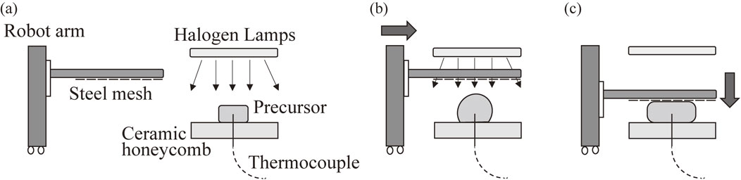
Figure 2 shows the foaming process of the precursor by optical heating and the subsequent press forming of the Al foam utilizing a steel mesh die. Four 2 kW halogen lamps aligned parallel to each other were used. The current and voltage applied to each lamp were 9 A and 180 V, respectively, throughout the experiments. A precursor was placed on a ceramic honeycomb, as shown in Fig. 2(a), with the initial surface of the precursor 40 mm from the lamps. Then, the lamps were turned on without the steel mesh placed between the lamps and the precursor. The precursor temperature T was observed utilizing a K-type thermocouple inserted into the center of the precursor. Press forming was conducted using an SUS 304 stainless steel mesh, as shown in Figs. 3(a) and (b), whose mesh opening ratio, sieve mesh size, and wire diameter were 66.9%, 1.30 mm, and 0.29 mm, respectively, in accordance with Ref. 20). As shown in Fig. 3(c), the steel mesh was attached to two parallel stainless steel bars using steel wires, which in turn were attached to a robot arm (Single Axis Robots RS2; MISUMI Group Inc., Tokyo, Japan) so that the steel mesh could be moved up and down. As shown in Fig. 2(b), the steel mesh was placed between the precursor and the lamps 40–50 s after T reached 530°C (solidus–liquidus coexistence region). The distance between the initial surface of the precursor and the surface of the steel mesh was approximately 25 mm. When T reached a certain value Tp, the steel mesh was pressed on the foamed precursor from above for 15 mm to obtain an Al foam of approximately 10 mm thickness, as shown in Fig. 2(c), after the lamps were turned off. It was reported that the ADC12 precursor began foaming in the solidus–liquidus temperature range (515–580°C) and vigorously foamed after the temperature exceeded the liquidus temperature.19) In this study, Tp was set to 580°C and 630°C, and the pressing velocity vp was set to 100 mm/s for Tp = 580°C and 1 mm/s, 50 mm/s, and 100 mm/s for Tp = 630°C, where 1 mm/s and 100 mm/s are the minimum and maximum velocities attained using the robot arm, respectively. In addition, free foaming without press forming was conducted for Tp = 630°C. The steel mesh was removed from the Al foam by moving the steel mesh upward after the Al foam was completely solidified below the solidus temperature.
The porosity p (%) of the entire Al foam was obtained by the equation
| \begin{equation*}
p = \frac{\rho_{\text{i}} - \rho_{\text{f}}}{\rho_{\text{i}}} \times 100,
\end{equation*}
|
where ρ
f is the density of the obtained Al foam evaluated by Archimedes’ principle and ρ
i is the density of the precursor before foaming. The density of the dense ADC12 Al alloy in accordance with Ref.
23) was used for ρ
i.
Microfocus X-ray computed tomography (CT) was utilized to observe the pore structures of the obtained Al foams. The voltage of the X-ray tube was 80 kV and the current was 30 µA. A cone-type CT system that can obtain a set of cross-sectional two-dimensional CT images of an entire Al foam was employed. Approximately 200 CT images were obtained. The equivalent length of a pixel was approximately 80 µm. The equivalent diameter d and circularity e of each pore were obtained by the equations
| \begin{equation*}
d = 2\left(\frac{A}{\pi} \right)^{\frac{1}{2}}
\end{equation*}
|
| \begin{equation*}
e = \frac{4\pi A}{L^{2}}
\end{equation*}
|
using the CT images, where
A and
L are the pore area and pore perimeter, respectively. A value of
e closer to 1 indicates a more circular pore. The average equivalent diameter
da and the average circularity
ea of the pores in the obtained Al foam were respectively evaluated as the average values of
d and
e of the pores in 30 CT images extracted at regular intervals. The pores with
da less than approximately 0.7 mm
2 were omitted from the evaluation of
da and
ea because they were noise in the image.
3. Results and Discussion
3.1 Tp = 580°C
Figure 4 shows the foaming and forming behavior during the heat treatment along with the precursor temperature T – heating time t relationship at Tp = 580°C and vp = 100 mm/s. t = 0 s was defined as the time when T reached 100°C after the lamps were turned on. (a)–(d) in Fig. 4(e) correspond to Figs. 4(a)–(d), respectively. (S) and (L) in Fig. 4(e) correspond to the solidus and liquidus temperatures, respectively. Figure 4(a) shows the precursor shortly after the lamps were turned on for heat treatment. When T exceeded the solidus temperature, as shown in Fig. 4(b), the precursor began to foam and gradually foamed in the solidus–liquidus coexistence region. The black diamond (◆) in Fig. 4(e) in the solidus–liquidus coexistence region indicates when the steel mesh was inserted between the lamps and the precursor. No decrease in the precursor temperature occurred even though the steel mesh was inserted, and the precursor was continuously heat-treated by the light irradiated through the mesh openings. Figure 4(c) shows the precursor just before the lamps were turned off. When T = 580°C, the steel mesh was pressed on the Al foam at vp = 100 mm/s immediately after the lamps were turned off. Figure 4(d) shows the precursor after the completion of the press forming. It was shown that Al foam can be press-formed by the steel mesh at T = 580°C. No extrusion of Al foam occurred from the mesh openings even when the steel mesh was pressed at vp = 100 m/s at the liquidus temperature. The Al foam and steel mesh were easily separated because only the wires of the steel mesh were in contact with the Al foam.

Figure 5(a) shows the obtained Al foam, whose upper surface was pressed with the steel mesh and whose lower surface was in contact with the ceramic honeycomb. Figure 5(b) shows its cross-sectional X-ray CT image, in which gray and black parts correspond to Al and pores, respectively. An Al foam with a plane upper surface was obtained by press forming. The pores were spherical, and a few elongated pores were observed even though press forming was applied. However, the square shape of the precursor was retained owing to insufficient foaming. The porosity of the obtained Al foam was p = 65.6%, which is lower than that obtained by the precursor foaming processes reported by other researchers.27,28) This is because vigorous foaming occurred after T exceeded the liquidus temperature.19) Therefore, although the Al foam was sufficiently softened to conduct press forming at 580°C, the press forming should be conducted after the precursor has been sufficiently foamed above the liquidus temperature. As reported in the next section, press forming was conducted at Tp = 630°C, at which the precursor can be sufficiently foamed.19)

Figure 6 shows the foaming and forming behavior during the heat treatment along with the T–t relationship at Tp = 630°C and vp = 100 mm/s. Figure 6(a) shows the precursor shortly after the lamps were turned on. The precursor gradually foamed in the solidus–liquidus coexistence region as shown in Fig. 6(b). Figure 6(c) shows the precursor just before the lamps were turned off. The precursor vigorously foamed when T exceeded the liquidus temperature and the precursor was sufficiently foamed at T = 630°C. The steel mesh was pressed on the precursor at vp = 100 m/s immediately after the lamps were turned off at T = 630°C. Figure 6(d) shows the precursor after the completion of the press forming. It was shown that the sufficiently foamed Al foam can be press-formed. No extrusion of Al foam through the mesh openings occurred even though the steel mesh was pressed at vp = 100 m/s above the liquidus temperature. The Al foam and steel mesh were easily separated after the Al foam had solidified.

Figures 7(a)–(d) show the foaming and forming behavior during the heat treatment and Fig. 7(e) shows the T–t relationship for Tp = 630°C and vp = 1 mm/s. The temperature of the Al foam decreased during the forming of the Al foam after the lamps were turned off. It was found that the Al foam can be press-formed by the steel mesh even though the forming was completed around the liquidus temperature for vp = 1 mm/s.
Figures 8(a)–(d) show the obtained Al foams and Figs. 8(e)–(h) show enlarged images of their surfaces pressed with the steel mesh at Tp = 630°C for various vp along with those of Al foam obtained by free foaming. An Al foam with plane upper surface was obtained and the mesh pattern was clearly observed on the surface of the Al foam regardless of vp, whereas the Al foam obtained by free foaming was almost spherical with an uneven rough surface.

Figures 8(i)–(l) show cross-sectional X-ray CT images corresponding to Figs. 8(a)–(d). The upper and lower surfaces were respectively pressed with the steel mesh and in contact with the ceramic honeycomb. The porosities of the foams were approximately 80%. It was found that there is no significant effect of conducting press forming on the pore structures of the obtained Al foams regardless of vp. These press-forming experiments were conducted three times for each vp. Similar tendencies were obtained for all Al foams. Namely, little collapse of the pores occurred even though the compression force of press forming was applied during foaming above the liquidus temperature. This is considered to be due to the observation that although the deformation of pores occurred during the movement of the steel mesh, foaming continued after the completion of press forming. The generated pores remained spherical because the Al matrix was sufficiently softened above the liquidus temperature and because of the surface tension of the pores. These results indicate that the press forming of Al foam can be conducted after sufficient foaming regardless of vp.
To determine the minimum temperature at which Al foam can be press-formed, Al foam that had been vigorously foamed by heating to 630°C similar to that in Figs. 6(c) and 7(c) was cooled to Tp = 580°C, 560°C, and 530°C, then press-formed at vp = 100 mm/s. As shown in Fig. 9, the Al foam cooled to Tp = 580°C could be sufficiently press-formed to obtain a similar Al foam to that in Fig. 8, whereas the Al foams cooled to Tp = 560°C and 530°C could not be press-formed at all. At Tp = 560°C and 530°C, the steel mesh was deformed rather than the Al foam. No mesh pattern was seen on the surface of the Al foams, similarly to the free-foamed Al foam shown in Fig. 8(h). This is considered to be due to solidification starting from the surface of the Al foam despite the inner Al foam still being in the solid–liquid coexistence region. The solidified surface of the Al foam showed higher resistance to the press-forming steel mesh.
3.3 Triangular Al foam
Figure 10(a) shows the steel mesh die used to fabricate an Al foam with a triangular cross section. The same steel mesh as that used in sections 3.1 and 3.2, as shown in Fig. 3, was bent to form a triangular shape. The steel mesh was easily bent by hand. The bent steel mesh was attached to the robot arm as shown in Fig. 3(c). Press forming was conducted at Tp = 630°C and vp = 100 mm/s. Figure 10(b) shows the vigorously foamed precursor just before the lamps were turned off. Figure 10(c) shows the precursor after the completion of the press forming. The press-formed Al foam sufficiently filled the top corner of the triangle as shown by the white arrow. Figures 10(d) and (e) show the obtained Al foam and its cross-sectional X-ray CT image, respectively. Al foam with a triangular cross section similar to the shape of the steel mesh was obtained. The porosity of the obtained Al foam was 78.4%, which is similar to those of the Al foams obtained in section 3.2. Note that a burr was observed on the left side of the Al foam. The burr can be reduced by supplying a sufficient amount of precursor to ensure that the entire volume of the die is filled by the Al foam.

Figure 11 shows the average equivalent diameter and average circularity of the pores of the obtained Al foams such as those shown in Figs. 8 and 10. Although there is some scatter, the press-formed Al foams including the triangular-shaped Al foam exhibited similar pore structures to those of Al foam obtained by free foaming.
Consequently, it was found that Al foam can be press-formed with a steel mesh die to fabricate Al foams with complex shapes without collapse or deformation of the pore structures of the Al foam regardless of vp.
4. Conclusions
Al foam was press-formed utilizing a steel mesh die during the foaming of the precursor to shape the Al foam. The following conclusions were obtained.
-
(1)
Al foam was sufficiently softened above the liquidus temperature to conduct press forming. In contrast, press forming cannot be conducted below the liquidus temperature.
-
(2)
The press forming of Al foam should be conducted after the Al foam has been sufficiently foamed above the liquidus temperature to obtain high-porosity Al foam.
-
(3)
No extrusion of Al foam through the mesh openings occurred even when press forming was conducted above the liquidus temperature. The Al foam and steel mesh were easily separated. The mesh pattern was clearly observed on the surface of the Al foams regardless of the pressing velocity vp.
-
(4)
There is little effect of conducting press forming on the pore structures of the obtained Al foams regardless of vp.
-
(5)
Al foam with a triangular cross section having the same shape as the steel mesh die and a porosity of approximately 80% was obtained. The press-formed Al foam sufficiently filled the steel mesh die.
Consequently, it was demonstrated that the press forming of Al foam after sufficient foaming is effective for fabricating Al foams with complex shapes.
Acknowledgments
This research is (partially) supported by the Matching Planner Program from Japan Science and Technology Agency, JST.
REFERENCES
- 1) J. Banhart: Prog. Mater. Sci. 46 (2001) 559–632.
- 2) F. García-Moreno: Materials 9 (2016) 85.
- 3) V. Crupi and R. Montanini: Int. J. Impact Eng. 34 (2007) 509–521.
- 4) F. Gagliardi, L. Filice, D. Umbrello and R. Shivpuri: Mater. Sci. Eng. A 480 (2008) 510–516.
- 5) R. Matsumoto, H. Tsuruoka, M. Otsu and H. Utsunomiya: J. Mater. Process. Technol. 218 (2015) 23–31.
- 6) Y. Hangai, N.N. Minh, T. Morita, R. Suzuki, M. Matsubara and S. Koyama: Adv. Powder Technol. 28 (2017) 1426–1429.
- 7) F. Baumgartner, I. Duarte and J. Banhart: Adv. Eng. Mater. 2 (2000) 168–174.
- 8) K. Kitazono, S. Nishizawa, E. Sato and T. Motegi: Mater. Trans. 45 (2004) 2389–2394.
- 9) K. Kitazono, E. Sato and K. Kuribayashi: Scr. Mater. 50 (2004) 495–498.
- 10) R. Suzuki, T. Nishimoto, Y. Hangai, I. Shoji and M. Matsubara: J. Japan Inst. Met. Mater. 82 (2018) 349–357.
- 11) Y. Hangai, T. Utsunomiya and M. Hasegawa: J. Mater. Process. Technol. 210 (2010) 288–292.
- 12) M. Azizieh, R. Pourmansouri, Z. Balak, H. Kafashan, M. Mazaheri and H.S. Kim: Arch. Metall. Mater. 62 (2017) 1957–1962.
- 13) Y. Hangai, K. Takada, R. Endoh, S. Koyama and T. Utsunomiya: J. Manuf. Process. 25 (2017) 426–431.
- 14) I.G. Papantoniou, H.P. Kyriakopoulou, D.I. Pantelis, A. Athanasiou-Ioannou and D.E. Manolakos: J. Mater. Sci. 53 (2018) 3817–3835.
- 15) P. Schäffler: Porous Metals and Metal Foaming Technology: MetFoam 2005, ed. by H. Nakajima and N. Kanetake, (The Japan Institute of Metals, Sendai, 2006) pp. 153–156.
- 16) L.E.G. Cambronero, I. Canadas, D. Martinez and J.M. Ruiz-Roman: Sol. Energy 84 (2010) 879–887.
- 17) J.A. Reglero, M.A. Rodriguez-Perez, E. Solorzano and J.A. de Saja: Mater. Des. 32 (2011) 907–910.
- 18) F. Garcia-Moreno, M. Fromme and J. Banhart: Adv. Eng. Mater. 6 (2004) 416–420.
- 19) Y. Hangai, K. Amagai, N. Tsurumi, K. Omachi, K. Shimizu, K. Akimoto, T. Utsunomiya and N. Yoshikawa: Mater. Trans. 59 (2018) 1854–1859.
- 20) Y. Hangai, K. Amagai, K. Omachi, N. Tsurumi, T. Utsunomiya and N. Yoshikawa: Opt. Laser Technol. 108 (2018) 496–501.
- 21) Y. Hangai, N. Tsurumi, K. Amagai, T. Utsunomiya and N. Yoshikawa: J. Japan Inst. Metals 82 (2018) 484–486.
- 22) Y. Hangai, H. Kamada, T. Utsunomiya, S. Kitahara, O. Kuwazuru and N. Yoshikawa: J. Mater. Process. Technol. 214 (2014) 1928–1934.
- 23) The-Japan-Institute-of-Light-Metals: Structures and properties of aluminum, (The Japan Institute of Light Metals Tokyo, 1991).
- 24) Y.S. Sato, S.H.C. Park, A. Matsunaga, A. Honda and H. Kokawa: J. Mater. Sci. 40 (2005) 637–642.
- 25) F. Khodabakhshi, A.P. Gerlich and P. Svec: Mater. Sci. Eng. A 698 (2017) 313–325.
- 26) Y. Hangai, K. Takahashi, R. Yamaguchi, T. Utsunomiya, S. Kitahara, O. Kuwazuru and N. Yoshikawa: Mater. Sci. Eng. A 556 (2012) 678–684.
- 27) M. Kobashi, M. Noguchi and N. Kanetake: Mater. Trans. 52 (2011) 934–938.
- 28) J. Banhart: Adv. Eng. Mater. 15 (2013) 82–111.


