Abstract
This paper reviews recent development of fabrication methods, various mechanical and physical properties of lotus-type porous metals and its application. The porous metals are fabricated by unidirectional solidification in pressurized gas atmosphere such as hydrogen, nitrogen and oxygen. The elongated pores are evolved from insoluble gas when the melt dissolving gas is solidified. Three fabrication techniques — mold casting, continuous zone melting and continuous casting techniques — are introduced. The latter two techniques can control the solidification velocity and the last one possesses a merit of mass production. Anisotropy observed in mechanical and physical properties is resulted from anisotropic pore morphology. The anisotropic behavior of tensile, compressive and fatigue strength is explained in terms of stress concentration depending upon pore orientation, while that of thermal and electrical conductivities is interpreted by anisotropic electron scattering. The porous metals exhibit good sound absorption and vibration-damping properties. Several possible applications of heat sinks, golf putters, machine tools and dental implants are introduced.
This Paper was Originally Published in Japanese in Materia Japan 58 (2019) 252–260.
1. Motivation of Research on Porous Metals
It is a great honor to receive the Japan Institute of Metals Gold Medal Award. The awarded reasons are his academic contribution to ① diffusion in solid metals and ② porous materials. The recipient Hideo Nakajima expresses sincere appreciation to former teachers, senior researchers, colleagues and laboratory students. Although his research spanned wide fields, only fabrication, properties and application of lotus-type porous metals (hereafter we call lotus-type porous metals as lotus metals, which means porous metals with long directional pores, whose shape looks like lotus roots.) will be described in this paper. When the author was appointed as a full professor in Iwate University in 1992, his research was expected to contribute to local companies. Many opportunities were arranged to visit and investigate iron foundries whose specialty was Nambu Ironwares. Their strong demand from local companies was to remove casting defects and shrinkage cavities from cast iron. However, since such research was conventional issues on which many researchers concerned, he considered not to be rich in originality. Instead, he decided to concentrate his own research to utilize the casting defects positively in order to fabricate new materials.
2. Porous Materials Widespread in Natural World
When we look around the natural world, we notice that a number of porous materials are existent such as woods, animal bones, leaves and stalks. Besides, artificial materials such as foods, clothes and buildings are not immaculate, but porous. Woods, leaves and stalks are porous materials with through holes, which play a role in vessel capillary tubes to supply moisture and nutrient. A bone consists of outer shell of dense and compact bone, enclosing a core of porous cellular, cancellous bone. The bone is designed to be lightened and the sectional area loaded is widened in order to release the stress in the joint part where a load is applied. The pore morphology of woods, bamboos and trabecular bones is anisotropic, and those mechanical strength changes, depending upon the pore orientation. Thus, the biomaterials are effectively designed in order to minimize the load and utilize fully the own mechanical strength, which is surprising and we, materials scientists should learn the concept of materials design of biomaterials.1–3)
By the way, the casting defects and sintering defects evolved in manufacturing process are considered to be harmful to impede the functionality and efficiency of industrial products. It is indispensable that these defects should be removed as much as possible. However, the attitude of the present research is different, and emphasizes effective utilization of pores and casting defects instead of removal.
While the pores of many porous materials such as foamed, cellular-structured and sintered metals are isotropic and polyhedron-shaped, the pores of lotus metals are anisotropic and directional.
3. Fabrication Methods of Lotus Metals using High-Pressure Gas Method
In metal-gas systems where the solubility of gas in molten metal is larger than that in solid metal, lotus metals can be fabricated by pore formation of insoluble gas when the melt dissolving gas is solidified. Lotus iron, nickel, copper, aluminum, magnesium and those alloys can be produced by using hydrogen as a dissolving gas. Using nitrogen or oxygen, lotus iron or silver can be fabricated, respectively.4) The following three methods are available to fabricate lotus metals.
3.1 Mold casting technique
Figure 1 shows schematic drawing of the mold casting technique to fabricate lotus metals. The melting part and solidification part are set up in pressurized gas chamber. After filling raw metallic materials into a crucible, the metals are melted by high-frequency induction heating, in which gas is dissolved under a given atmospheric pressure. The melt is poured into a copper-made mold whose bottom is cooled by a chiller, and is solidified unidirectionally from the bottom upward. Thus, the elongated pores grow in the direction of solidification.5,6) Since unidirectional solidification takes place by cooling one side of the mold, the size of the ingot of lotus metals is limited in this technique.
3.2 Continuous zone melting technique
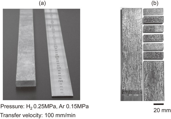
As shown in Fig. 2, lotus copper and magnesium with uniform pore size and porosity can be fabricated by mold casting technique because of high thermal conductivity of the metals. However, for the metals with low thermal conductivity lotus metals with uniform pore size and porosity cannot be made. Since the solidification velocity is fast in the cooling part near chiller, fine pores are evolved. On the other hand, since at a part far from the chiller the solidification velocity becomes slower and the pores are coarsened. As a result, lotus metals with uniform pore size and porosity could not be produced.7) In order to overcome this difficulty, continuous zone melting technique was developed as shown in Fig. 3.8) In pressurized gas atmosphere, metal rod is partially melted by induction heating coil. The melt zone absorbs gas to the equilibrium gas concentration, which is then transferred continuously with constant transfer velocity so that lotus metal rod with uniform pore size and porosity is fabricated. Figure 3(d) shows the fabricated lotus stainless steel. It is apparent that every section exhibits uniform pore size and porosity.

The dimensions of lotus metals produced by the mold casting and continuous zone melting techniques are limited. To practically realize the mass production, large sized lotus metals should be fabricated. For this purpose a continuous casting technique was invented.9–11) In conventional continuous casting technique for production of non-porous metals, a solidified ingot can be transferred smoothly through fixed mold because of solidification shrinkage. On the other hand, since volumetric expansion occurs when lotus metals are solidified, it is suspected that the solidified ingot cannot pass through the mold. However, such volumetric expansion is led to the molten metal with fluidity so that the ingot can pass through the mold smoothly without any problem. Figure 4 shows schematic drawing of apparatus for continuous casting technique, which consists of melting part, casting part and ingot transference mechanism. The molten metal melted in a crucible by induction heating passes through the mold cooled by the chiller. The solidified ingot is pulled down by dummy bar which is transferred downward by pinch rollers. Thus, long ingot of lotus metal is continuously produced at the constant solidification velocity.

Lotus copper slab fabricated by continuous casting technique is exhibited in Fig. 5. Figure 6 shows transfer velocity dependence of average pore diameter of lotus copper. The pore diameter significantly decreases with increase of transfer velocity. The formation of such fine sized pores is attributed to increase of pore nucleation sites due to supercooling.9)
4. Fabrication Methods of Lotus Metals using Thermal Decomposition Method
High-pressure gas method possesses two disadvantages: (1) necessity of high-pressure chamber and application of high-pressure regulation and (2) necessity of safety procedure to protect against hydrogen as an inflammable and explosive gas. A technique that does not require high-pressure hydrogen to fabricate lotus metals is highly desirable. Nakajima and Ide developed an alternative, but simple method to fabricate lotus metals by using a thermal decomposition method of compounds containing gas elements in a non-hydrogen atmosphere under nearly atmospheric pressure.12) Figure 7 shows the fabrication principle of the thermal decomposition method through mold casting technique. Pellets of titanium hydride powder are placed on the bottom of the mold which is cooled by a water chiller. Molten copper melted by induction heating is poured into the mold in argon atmosphere of 0.1 MPa, and the hydride simultaneously dissociates into hydrogen which is responsible to form hydrogen pores. Then, the directional solidification takes place to elaborate lotus copper. Figure 8 exhibits the optical micrographs of the cross-sectional views of lotus copper parallel and perpendicular to the solidification direction. The porosity of about 60% keeps constant, even if titanium hydride more than 0.1 g is given in the melt. Constant porosity by addition of titanium hydride more than 0.1 g is reasonable, since the concentration of hydrogen evolved by dissociation of titanium hydride of 0.1 g in copper of 200 g exceeds the equilibrium solubility. Thus, lotus metals can be fabricated in inexpensive, safe and simple manner by addition of hydride12,13) or nitride14) during directional solidification.

5. Mechanical Properties of Lotus Metals
5.1 Tensile strength of lotus metals
A number of investigations on mechanical properties of foamed and sintered metals with isotropic, spherical pores were carried out in the past. However, mechanical tests of lotus metals were hardly investigated except Wolla and Provenzano15) and Simone and Gibson.16) As shown in Fig. 9, Hyun et al. investigated porosity dependence of ultimate tensile strength and yield strength of lotus copper fabricated using hydrogen.17) The data points for the ultimate tensile strength lie on a straight line which passes through the point of 0 MPa at the porosity of 100%; the specific ultimate tensile strength does not change by the pore existence. This fact indicates that the pores aligned parallel to the tensile direction cause little stress concentration in the tensile specimens.
The strength σ of porous materials is expressed by the following empirical equation18)
| \begin{equation}
\sigma = \sigma_{0}(1 - p)^{K}
\end{equation}
| (1) |
where
p is the porosity and σ
0 is the strength of non-porous materials.
K is the coefficient of stress concentration, which depends on shape and orientation of the pores and is shown as
K = σ
max/σ, where σ
max is the maximum of stress.
Figure 10 shows the stress distribution around an ellipse-shaped pore and round pore. The maximum stress can be expressed by
| \begin{equation}
\sigma_{\textit{max}} = \sigma (1 + 2a/b)
\end{equation}
| (2) |
where
a and
b are the semimajor axis and semiminor axis, respectively.
K value for lotus metals with pores elongated in the direction parallel to the tensile direction is 1 and
eq. (1) becomes to σ = σ
0(1 −
p). On the other hand, in the case of perpendicular direction,
K = 3 and σ = σ
0(1 −
p)
3. The theoretical curves evaluated from
eq. (1) and
eq. (2) are fitted well to experimental values as shown in
Fig. 9. Therefore, it is concluded that (1) the ultimate tensile strength of lotus copper with pore orientation parallel to the tensile direction is hardly affected by stress concentration, and (2) the ultimate tensile strength of lotus copper with pore orientation perpendicular is affected by stress concentration which is accumulated in the vicinity of the pore.

By the way, a number of metals and alloys can be perforated through directional solidification by using hydrogen. However, this fabrication method using hydrogen is not suitable for mass production because hydrogen explosive and inflammable gas. Hyun and Nakajima succeeded in fabricating lotus iron using safe gas of nitrogen.19) The use of nitrogen has additional merit that the strength of lotus iron fabricated using nitrogen is much higher than that using hydrogen.20) Figure 11 exhibits the tensile strength of lotus iron fabricated using nitrogen and hydrogen as a function of porosity. Even if the porosity is 40–50%, the strength of lotus iron fabricated using nitrogen is similar to that of non-porous iron, which is very interesting result. That is, lotus iron has similar strength of iron, but the weight is half. Such behavior is attributed to solid solution hardening due to nitrogen.
5.2 Compressive strength of lotus metals with low compressive strain rate
Compressive tests of foamed metals were actively investigated. Plateau region was found in the stress-strain curves in the compression tests of foamed metals, where the stress is not changed to keep constant in spite of strain increasing. In this region the compressive energy is absorbed by collapse of the pores. Hyun and Nakajima investigated systematically the compressive behavior of lotus copper with elongated pores parallel and perpendicular to the compressive direction for the first time.21) As shown in Fig. 12, the gradient of the stress-strain curves decreases with increasing porosity. Comparing the compressive stress parallel to the pore direction with that perpendicular at the same porosity, the compressive strength parallel to the pore direction is higher than that perpendicular in the region of lower strain. However, the strength magnitude reverses with increasing strain. The weakness of compressive strength perpendicular to the pore direction is attributed to the stress concentration, while no stress concentration occurs in compressive strength parallel to the pore direction.

Figure 13 shows the nominal stress-nominal strain curves of lotus iron with elongated pores parallel and perpendicular to compressive direction at the low, middle and high strain rate. Compression tests with high strain rate (∼103 s−1) in the direction parallel and perpendicular to the pore orientation were carried out with the split Hopkinson pressure bar method. Low (∼10−4 s−1) and middle (∼10−1 s−1) strain rate compression tests were also performed by a universal Instron testing machine. Influence of strain rate and pore orientation on compressive deformation and energy absorption were investigated.22,23) Compressive stress σ - strain ε curves in compression test of lotus metals with high porosity is divided into three regions: elastic region, plateau region and densification region. The energy W absorbed during the compressive deformation is estimated by
| \begin{equation}
W = \int_{0}^{\varepsilon_{D}}\sigma (\varepsilon)\,d\varepsilon
\end{equation}
| (3) |
where ε
D is the strain at which the densification starts. In both compressive directions parallel and perpendicular to the pore orientation the flow stress increases with increase of strain rate. This is attributed to increase of flow stress of matrix iron in association with increasing strain rate. In compression at low and middle strain rate, the flow stress of lotus iron with the pores parallel to compression direction monotonically increases. The flow stress at high strain rate decreases with increasing strain in the range of plastic strain from 15.0% to 22.5%, and the plateau region appears. On the other hand, the flow stress of lotus iron with the pores perpendicular to compression direction monotonically increases with increasing strain in spite of strain rate, and no plateau region appears. Appearance of plateau region considered to be attributed to buckling distortion.

The absorbed energy per unit weight of lotus iron with the pores parallel and perpendicular to the compression direction was evaluated from the high strain rate compression test to be 30 kJ·kg−1 and 15 kJ·kg−1, respectively. These absorbed energy is much larger than that of foamed aluminum (2∼8 kJ·kg−1). In particular, the absorbed energy in the parallel direction is four times larger than that of foamed aluminum. Thus, lotus iron exhibits superior absorbed energy characteristics.
6. Physical Properties of Lotus Metals
6.1 Sound absorption of lotus metals
Although glass wool and foamed aluminum with closed pores are used most frequently as marketed sound-absorbing materials at present, these materials have not enough strength. If not only the light-weight but also sufficient strength are given, wide application for sound-absorbing becomes possible for various needs. Xie et al. reported that lotus metals exhibit good sound absorbing property.24) The sound absorption coefficient α0 is defined by
| \begin{equation}
\alpha_{0} = (I_{0} - I_{r})/I_{0}
\end{equation}
| (4) |
where
I0 and
Ir are the energy of incident sound wave and the energy of reflection sound wave, respectively. The sound absorption coefficients were measured by standing-wave method as functions of pore diameter, porosity and thickness of samples. The followings are elucidated; (1) α
0 increases with decreasing pore diameter under constant porosity and thickness, (2) α
0 increases with increasing porosity under constant pore diameter and thickness, and (3) α
0 increases with increasing thickness under constant pore diameter and porosity. It is concluded that the viscosity resistance of air in inner wall of pores plays an important role in absorbing the sound. The above-mentioned results indicate that the sound absorption increases with increasing area of inner wall of pores.
The absorption coefficients of lotus copper, the foamed aluminum and glass wool with the same thickness, in the same frequency region, were compared as shown in Fig. 14. The foamed aluminum is composed of many independent closed pores. Continuous pores are necessary to have high-sound absorption capacity so that minute cracks are introduced by rolling to connect the pores. Since the porosity is different in three materials, direct comparison is impossible. However, although the porosity of lotus copper is lower, lotus metals possess superior sound absorbing property comparing with commercially available materials.
6.2 Thermal conductivity of lotus metals
When lotus metals will be used for heat sinks, the knowledge of thermal conductivity is important as fundamental physical parameters. The thermal conductivity of lotus copper was measured through steady state method by Ogushi et al.25) Remarkable anisotropic thermal conductivity due to pore orientation was found. Effective thermal conductivity keff of lotus copper is defined as
| \begin{equation}
q = Q/A = - k_{\textit{eff}}\nabla T
\end{equation}
| (5) |
where
q is a heat flux from heat flow
Q flowing through the sectional area
A in lotus copper including pores, and
T is the temperature of lotus copper. Since the heat flow parallel to the elongated pores is proportional to the sectional area of lotus copper which is expressed as (1 − ε), the effective thermal conductivity
keff∥ is shown as
| \begin{equation}
k_{\textit{eff}\|}/k_{s} = 1 - \varepsilon
\end{equation}
| (6) |
where
ks is the thermal conductivity of non-porous copper and ε is the porosity. On the other hand, the effective thermal conductivity perpendicular to the pores
keff⊥ is given by
| \begin{equation}
k_{\textit{eff}\bot}/k_{s} = (1 - \varepsilon)/(1 + \varepsilon)
\end{equation}
| (7) |
shows a comparison of the experimental data with the results evaluated by the analytical
eqs. (6) and
(7). The experimental data are in good agreement with the results evaluated by the analytical equations. The effective thermal conductivity perpendicular to the pores is lower than that parallel to the pores. Such anisotropy is attributed to anisotropic scattering of electrons with the directional pores.
6.3 Electrical conductivity of lotus metals
The electrical conductivity parallel and perpendicular to the pore direction was measured by four-probe method at room temperature, whose conductivity is shown as σ∥ and σ⊥, respectively. Figure 16 shows the measurement result of the electrical conductivity of lotus nickel as a function of porosity.26) Significant anisotropy in the electrical conductivity was observed depending on pore orientation; σ∥ is higher than σ⊥. The specific electrical conductivity parallel to the pore direction is almost constant independent of the porosity. Since increase in porosity results in decrease in the number of current carriers when the current carriers flow in the direction parallel to the pore orientation, the electrical conductivity decreases linearly with increase of porosity. On the contrary, the electrical conductivity perpendicular to the pore orientation is much lower than that parallel. When the current carriers flow in the perpendicular direction, the current carriers flow making a detour around the pores or scattering with the pore surface. It is considered that the distance at which the current carriers migrate increases so that the electrical resistivity increases.

7. Unified Interpretation of Anisotropy in Mechanical Strength and Physical Properties of Lotus Metals
It is apparent that porosity dependence of mechanical strength, thermal conductivity and electrical conductivity of lotus metals equally obeys the power-law equation shown by eq. (1). While dislocation behavior is responsible for strength of materials, electron behavior is responsible for thermal conduction and electron conduction. If pores are existent in metals, stress concentration occurs by dislocation pinning at pores during plastic deformation. Thus, the strength of lotus metals with the pores perpendicular to loading direction decreases significantly. The pores are considered as the pinning sites to interrupt multiplication of dislocations. On the other hand, though thermal conduction takes place in general by lattice vibration and electronic conduction, the electronic conduction is dominant in metals. The thermal conductivity may be decreased by electrons which make a detour around the pores or scatter with the pore surface. The electronic conductivity is also decreased in the similar way.
Figure 17 shows the cross-section of pores in lotus metals parallel and perpendicular to the pore direction. The cross-sectional area S is evaluated approximately to be;
| \begin{equation}
\text{Parallel to the pore direction $S_{\|}$} = \pi \sum\nolimits_{i = 1}^{n}r_{i}^{2}
\end{equation}
| (8) |
| \begin{equation}
\text{Perpendicular to the pore direction $S_{\bot}$} = 2 \sum\nolimits_{i = 1}^{n}r_{i}l_{i}
\end{equation}
| (9) |
where
n is the number of pores per unit volume,
r is the radius of pore and
l is the length of pore. Usually
li ≫
ri so that
S⊥ >
S∥. Therefore, the pinning cross-sectional or the scattering cross-sectional area perpendicular to the pore direction is much larger than that parallel to the pore direction. Significant anisotropy in mechanical strength, thermal conductivity and electrical conductivity is attributed to large difference in the cross-sectional area of pores in lotus metals.
27)
8. Application of Lotus Metals
In recent years, heat dissipation rates in power devices and laser diodes have been increasing to more than 100 W/cm2 and in high-frequency electronic devices, it is increasing to more than 1,000 W/cm2 under the trend of miniaturization and growing capacity. Conventional groove-fin type heat sinks cannot attain such large heat dissipation from the devices. Therefore, novel heat sinks with high heat transfer performance are required to cool these devices. Lotus metals with straight pores are preferable for heat sinks due to large surface area and small pressure drop of the cooling fluid flowing through the pores. Figure 18(a) and (b) show conventional groove fins and lotus metal fins, respectively. Figure 18(c) illustrates the experimental apparatus for measuring the heat transfer capacity of the heat sinks. Cooling air is blown by a blower into the test duct in which the heat sink is located. The heat sink consists of fins brazed on one side of a copper baseplate and heating block with a heater soldered to the other side of the baseplate. The inlet temperature of cooling air Ti, the temperature of copper baseplates Tb1, Tb2 and Tb3, and the outlet temperature of the cooling air T0 are measured by thermocouples. The heat transfer capacity with heat transfer coefficient hb based on baseplate area Ab of the heat sink is as follows:
| \begin{equation}
h_{b} = Q/(A_{b}(T_{b} - T_{i}))
\end{equation}
| (10) |
where Q is the heat input to the heat sink. Chiba
et al. measured the heat transfer coefficient as a function of inlet velocity as shown in
Fig. 19. The experimental data for lotus heat sink with fin thickness
L = 1 mm shows very large heat transfer coefficient of 5,000 W/(m
2K) under an inlet velocity of 1.0 m/s, which is 13.2 times higher than that for the conventional groove fins. Thus, the heat sinks whose fins are made of lotus copper is the most superior among available heat sinks.
28,29) These air-cooling and water-cooling heat sinks made of lotus copper will be used to large capacity LED (light-emitting diode) which is installed to commercial projectors. Besides, those are scheduled to be applied to IGBT (insulated gate bipolar transistor) for computers and cars.
High damping capacity was found in lotus metals. Lotus copper was adopted to the head of golf putter, which was commercialized. It is said that feeling of hitting a ball by the golf putter is mild because of excellent vibration-damping.30) Hereafter, lotus metals are expected to be used and commercialized for shock-absorbing materials,2,4) vibration-damping materials,3,31) sound-absorbers,3,24) medical devices,32,33) thermoelectric materials, etc.
9. Concluding Remark
The present author has engaged in his research life for 45 years. In his first half term the basic research of atomic diffusion in metals was carried out and in his latter half term the development research of porous metals was performed. The knowledge and experience on diffusion which was investigated was very useful for latter development research. The research on materials development is always apt to pertain to failure. Even if awkward lotus metals were fabricated, the present author was not disappointed. Because he often could obtain the solutions for the cause of failure, which was encouraged and brought on his motive force to develop further research step. It was not surely confident for him whether the research on lotus metals originated from solidification defects could be science or not. Therefore, for several years after he did begin to investigate lotus metals, he had continued his research alone without cooperation of his laboratory staffs and students. However, in this opportunity to move from Iwate University to Osaka University, the research of lotus metals was set up as a main research subject in his laboratory so that his laboratory was changed from “science research laboratory” to “development research laboratory”. Afterthat, systematic investigations on fabrication, properties and application of lotus metals were carried out in collaboration with laboratory members and colleagues in and out campus, to whom he would like to acknowledge. In future, it is hoped that porous materials science will be developed further and its application should expand to various industries.
REFERENCES
- 1) L.J. Gibson and M.F. Ashby: Cellular Solids, (Cambridge University Press, Cambridge, UK, 1997).
- 2) H. Nakajima: Porous Metals with Directional Pores, (Springer, Tokyo, Heidelberg, New York, Dordrecht, London, 2013).
- 3) H. Nakajima: Porous Materials Science – New Functional Materials Fabricated by Perforation –, (Uchidaroukakuho, Tokyo, 2016) (in Japanese).
- 4) H. Nakajima: Prog. Mater. Sci. 52 (2007) 1091–1173.
- 5) V. Shapovalov: MRS Symp. Proc. 521 (1998) 281–290.
- 6) H. Nakajima, S.K. Hyun, K. Ohashi, K. Ota and K. Murakami: Colloids Surf. A 179 (2001) 209–214.
- 7) T. Ikeda, M. Tsukamoto and H. Nakajima: Mater. Trans. 43 (2002) 2678–2684.
- 8) T. Ikeda, T. Aoki and H. Nakajima: Metall. Mater. Trans. A 36 (2005) 77–86.
- 9) J.S. Park, S.K. Hyun, S. Suzuki and H. Nakajima: Acta Mater. 55 (2007) 5646–5654.
- 10) J.S. Park, S.K. Hyun, S. Suzuki and H. Nakajima: Metall. Mater. Trans. A 40 (2009) 406–414.
- 11) T. Ide, Y. Iio and H. Nakajima: Metall. Mater. Trans. A 43 (2012) 5140–5152.
- 12) H. Nakajima and T. Ide: Metall. Mater. Trans. A 39 (2008) 390–394.
- 13) S.Y. Kim, J.S. Park and H. Nakajima: Metall. Mater. Trans. A 40 (2009) 937–942.
- 14) T. Wada, T. Ide and H. Nakajima: Metall. Mater. Trans. A 40 (2009) 3204–3209.
- 15) J.M. Wolla and V. Provenzano: MRS Symp. Proc. 371 (1995) 377–382.
- 16) A.E. Simone and L.J. Gibson: Acta Mater. 44 (1996) 1437–1447.
- 17) S.K. Hyun, K. Murakami and H. Nakajima: Mater. Sci. Eng. A 299 (2001) 241–248.
- 18) M.Y. Balshin: Doklady Akad. Sci. USSR 67 (1949) 831–996.
- 19) S.K. Hyun and H. Nakajima: Mater. Trans. 43 (2002) 526–531.
- 20) S.K. Hyun, T. Ikeda and H. Nakajima: Sci. Technol. Adv. Mater. 5 (2004) 201–205.
- 21) S.K. Hyun and H. Nakajima: Mater. Sci. Eng. A 340 (2003) 258–264.
- 22) M. Tane, T. Kawashima, H. Yamada, K. Horikawa, H. Kobayashi and H. Nakajima: J. Mater. Res. 25 (2010) 1179–1190.
- 23) Y.H. Song, M. Tane and H. Nakajima: Acta Mater. 60 (2012) 1149–1160.
- 24) Z.K. Xie, T. Ikeda, Y. Okuda and H. Nakajima: Mater. Sci. Eng. A 386 (2004) 390–395.
- 25) T. Ogushi, H. Chiba, H. Nakajima and T. Ikeda: J. Appl. Phys. 95 (2004) 5843–5847.
- 26) M. Tane, S.K. Hyun and H. Nakajima: J. Appl. Phys. 97 (2005) 103701.
- 27) H. Nakajima: Mater. Sci. Appl. 9 (2018) 258–267.
- 28) H. Chiba, T. Ogushi and H. Nakajima: J. Thermal Sci. Tech. 5 (2010) 222–237.
- 29) H. Chiba, T. Ogushi and H. Nakajima: Proc. ASME/JSME 2011 8th Thermal Engineering Joint Conf., (AJTEC2011), (2011) pp. 1–9.
- 30) Z.K. Xie, M. Tane, S.K. Hyun, Y. Okuda and H. Nakajima: Mater. Sci. Eng. A 417 (2006) 129–133.
- 31) M. Kashihara, K. Yamamoto, M. Furuta, H. Yonetani, T. Tsumura, K. Nakata, S.Y. Kim, S. Suzuki and H. Nakajima: Trans. Jpn. Soc. Mech. Eng. Ser. C 77 (2011) 4693–4703 (in Japanese).
- 32) Y. Higuchi, Y. Ohashi and H. Nakajima: Adv. Eng. Mater. 8 (2006) 907–912.
- 33) K. Alvarez, S.K. Hyun, S. Fujimoto and H. Nakajima: J. Mater. Sci. Mater. Med. 19 (2008) 3385–3397.