Magnetic Properties of SmFe3-Type Sm–Zr–Fe–Co–Ti Melt-Spun Ribbons
2019 Volume 60 Issue 7 Pages 1384-1389
Details
2019 Volume 60 Issue 7 Pages 1384-1389
The magnetic properties and structures of (Sm,Zr)5(Fe,Co)17−xTix (x = 0–2.0) melt-spun ribbons were investigated in the as-quenched condition and after annealing. The as-quenched (Sm,Zr)5(Fe,Co)17−xTix (x = 0–0.5) specimens consisted of the Sm5Fe17-type and SmFe3-type phases, while the as-quenched (Sm,Zr)5(Fe,Co)17−xTix (x = 1.0–2.0) specimens contained the SmFe3-type phase. These specimens showed low coercivity regardless of the Ti content. Heat treatment of the melt-spun ribbons resulted in a drastic increase in coercivity. The maximum coercivity of 1.11 MAm−1 was achieved in the (Sm,Zr)5(Fe,Co)15.5Ti1.5 specimen annealed at 1073 K. Microstructural studies revealed that the annealed specimen consisted mainly of the SmFe3-type phase. The achieved high coercivity of the annealed specimen was therefore attributed to the existence of the SmFe3-type phase.
The Sm5Fe17-type phase is a new ferromagnetic intermetallic compound in the binary Sm–Fe system and is a candidate for a new permanent magnet.1–7) The Sm5Fe17-type phase has been shown to be a metastable phase.8) Although the Sm5Fe17-type phase exhibits high coercivity comparable to that of Nd–Fe–B permanent magnets, the reported values of its remanence are relatively low. Several efforts have been made to increase the remanence of the Sm5Fe17-type phase, but it has been reported that the large compositional modification of the Sm5Fe17-type phase resulted in its decomposition.9,10) During studies on Sm5Fe17-type alloys, it has been found that the addition of Ti to the (Sm,Zr)5(Fe,Co)17 alloys resulted in the formation of the SmFe3-type phase. It was also found that specimens with the SmFe3-type phase exhibited high levels of coercivity.11) It has been reported that the SmFe3 phase has a rhombohedral structure12–14) and that the substitution of Zr for Sm in the SmFe3 phase increased the coercivity.15,16) In this study, the magnetic properties and structures of these SmFe3-type Sm–Zr–Fe–Co–Ti specimens were investigated.
Alloy ingots with nominal compositions of (Sm1−xZrx)5(Fe0.75Co0.25)17 (x = 0–0.4) and (Sm0.8Zr0.2)5(Fe0.75Co0.25)17−xTix (x = 0–2.0) were prepared by induction melting in an argon atmosphere.17) The alloy ingots were placed in a silica crucible with an orifice of 0.6 mm in diameter and then melt-spun onto a chromium-plated copper wheel rotating at a tangential wheel velocity of 40 ms−1. Heat treatments of the as-quenched melt-spun ribbons were performed in an argon atmosphere for 1 h at temperatures between 773 K and 1273 K.
The crystal structures of the specimens were investigated by X-ray diffraction (XRD) using Cu Kα radiation. Selected specimens were further investigated using synchrotron radiation X-ray diffraction (SR-XRD). The thermomagnetic properties of the specimens were investigated under a small magnetic field of 0.04 MAm−1 using a vibrating sample magnetometer (VSM). The hysteresis loops of the specimens were investigated at room temperature using VSM under a maximum magnetic field of 2.0 MAm−1. No demagnetization corrections were made in this experiment.
The crystal structures of the as-quenched (Sm1−xZrx)5(Fe0.75Co0.25)17 (x = 0–0.4) melt-spun ribbons were investigated in the XRD study. The results are shown in Fig. 1. The XRD pattern of the Sm5(Fe0.75Co0.25)17 alloy shows a fairly broad halo-like peak, as was the case for the Sm5Fe17 alloy.8) Virtually the same XRD patterns are obtained for the (Sm0.9Zr0.1)5(Fe0.75Co0.25)17 and (Sm0.8Zr0.2)5(Fe0.75Co0.25)17 alloys, indicating that these alloys are amorphous. Unlike the XRD patterns of the (Sm1−xZrx)5(Fe0.75Co0.25)17 (x = 0–0.2) alloys, small diffraction peaks are noted in the XRD patterns of the (Sm0.7Zr0.3)5(Fe0.75Co0.25)17 and (Sm0.6Zr0.4)5(Fe0.75Co0.25)17 alloys. These peaks are embedded in a halo-like peak and are too weak to be indexed to any crystalline phase. This suggests that the (Sm0.7Zr0.3)5(Fe0.75Co0.25)17 and (Sm0.6Zr0.4)5(Fe0.75Co0.25)17 alloys consist of the amorphous phase together with some crystalline phase. It is found that the small substitution of Zr for Sm in the Sm5(Fe0.75Co0.25)17 alloy does not affect the glass-forming ability of the alloy but that the large substitution of Zr for Sm in the Sm5(Fe0.75Co0.25)17 alloy results in the formation of the crystalline phase together with the amorphous phase.

XRD patterns of (a) Sm5(Fe0.75Co0.25)17, (b) (Sm0.9Zr0.1)5(Fe0.75Co0.25)17, (c) (Sm0.8Zr0.2)5(Fe0.75Co0.25)17, (d) (Sm0.7Zr0.3)5(Fe0.75Co0.25)17, and (e) (Sm0.6Zr0.4)5(Fe0.75Co0.25)17 melt-spun ribbons.
Since the as-quenched melt-spun specimens were either amorphous or partially amorphous and exhibited low coercivity values regardless of the Zr content. Thus, annealing of as-quenched melt-spun specimens was carried out. Figure 2 shows the dependence of the coercivity of the (Sm1−xZrx)5(Fe0.75Co0.25)17 (x = 0–0.4) melt-spun ribbons on the annealing temperature. The coercivity of the (Sm1−xZrx)5(Fe0.75Co0.25)17 (x = 0–0.3) alloys increases as the annealing temperature increases. However, the coercivity of the (Sm0.6Zr0.4)5(Fe0.75Co0.25)17 alloy is not changed by annealing. This is due to the smaller amount of the amorphous phase in the (Sm0.6Zr0.4)5(Fe0.75Co0.25)17 alloy. The highest coercivity of 0.60 MAm−1 was achieved in the (Sm0.8Zr0.2)5(Fe0.75Co0.25)17 specimen after annealing at 1073 K.

Dependence of the coercivity of the (Sm1−xZrx)5(Fe0.75Co0.25)17 (x = 0–0.4) melt-spun ribbons on the annealing temperature.
The structures of the (Sm1−xZrx)5(Fe0.75Co0.25)17 (x = 0–0.4) melt-spun ribbons annealed at 1073 K were examined by XRD. Figure 3 shows the XRD patterns of the annealed (Sm1−xZrx)5(Fe0.75Co0.25)17 (x = 0–0.4) melt-spun ribbons. The annealed Sm5(Fe0.75Co0.25)17 alloy showed diffraction peaks that is assigned to the Sm5Fe17-type phase. It was found that the observed diffraction peaks of the Sm5Fe17-type phase become wider and broader as the Zr content increases. The (Sm0.6Zr0.4)5(Fe0.75Co0.25)17 alloy showed diffraction peaks that may be assigned to the SmFe3-type phase. Since the diffraction pattern of the Sm5Fe17-type phase is similar in appearance to that of the SmFe3-type phases, it is difficult to distinguish these phases in the annealed alloys.

XRD patterns of (a) Sm5(Fe0.75Co0.25)17, (b) (Sm0.9Zr0.1)5(Fe0.75Co0.25)17, (c) (Sm0.8Zr0.2)5(Fe0.75Co0.25)17, (d) (Sm0.7Zr0.3)5(Fe0.75Co0.25)17, and (e) (Sm0.6Zr0.4)5(Fe0.75Co0.25)17 melt-spun ribbons annealed at 1073 K.
It has been reported that the small substitution of Ti for Fe in the Sm5Fe17 melt-spun ribbon stabilized the Sm5Fe17 phase.18) Thus, the (Sm0.8Zr0.2)5(Fe0.75Co0.25)17−xTix (x = 0–2.0) melt-spun ribbons were prepared and the structures and magnetic properties were examined. Figure 4 shows the XRD patterns of the (Sm0.8Zr0.2)5(Fe0.75Co0.25)17−xTix (x = 0–2.0) melt-spun ribbons. No clear diffraction peaks are found in the XRD pattern of the (Sm0.8Zr0.2)5(Fe0.75Co0.25)17 specimen. On the other hand, small diffraction peaks are seen in the XRD patterns of the (Sm0.8Zr0.2)5(Fe0.75Co0.25)17−xTix (x = 0.5–2.0) specimens. Since the peaks are somewhat weak and broad, it is impossible to identify the crystalline phases from the XRD patterns.

XRD patterns of (a) (Sm0.8Zr0.2)5(Fe0.75Co0.25)17, (b) (Sm0.8Zr0.2)5(Fe0.75Co0.25)16.5Ti0.5, (c) (Sm0.8Zr0.2)5(Fe0.75Co0.25)16Ti1.0, (d) (Sm0.8Zr0.2)5(Fe0.75Co0.25)15.5Ti1.5, and (e) (Sm0.8Zr0.2)5(Fe0.75Co0.25)15Ti2.0 melt-spun ribbons.
In order to identify the crystalline phases in the specimens, thermomagnetic measurements were carried out. The results of the thermomagnetic study are shown in Fig. 5. The thermomagnetic curve of the (Sm0.8Zr0.2)5(Fe0.75Co0.25)17 specimen shows two magnetic transitions at around 550 K and 690 K. The former magnetic transition corresponds to the Curie temperature of the Sm5Fe17-type phase and the latter to the Curie temperature of the SmFe3-type phase. These magnetic transitions were also seen in the (Sm0.8Zr0.2)5(Fe0.75Co0.25)16.5Ti0.5 specimen, but only the latter magnetic transition was found in the (Sm0.8Zr0.2)5(Fe0.75Co0.25)17−xTix (x = 1.0–2.0) specimens. This suggests that the (Sm0.8Zr0.2)5(Fe0.75Co0.25)17−xTix (x = 0–0.5) specimens consisted of the Sm5Fe17-type and SmFe3-type phases and that the (Sm0.8Zr0.2)5(Fe0.75Co0.25)17−xTix (x = 1.0–2.0) specimens mainly consisted of the SmFe3-type phase. A small kink was also noted at around 630 K in the thermomagnetic curves of the (Sm0.8Zr0.2)5(Fe0.75Co0.25)17−xTix (x = 1.0–2.0) specimens. This indicates that these specimens also contained a small amount of an unidentified phase.

Thermomagnetic curves of (a) (Sm0.8Zr0.2)5(Fe0.75Co0.25)17, (b) (Sm0.8Zr0.2)5(Fe0.75Co0.25)16.5Ti0.5, (c) (Sm0.8Zr0.2)5(Fe0.75Co0.25)16Ti1.0, (d) (Sm0.8Zr0.2)5(Fe0.75Co0.25)15.5Ti1.5, and (e) (Sm0.8Zr0.2)5(Fe0.75Co0.25)15Ti2.0 melt-spun ribbons.
Figure 6 shows the hysteresis loops of the (Sm0.8Zr0.2)5(Fe0.75Co0.25)17−xTix (x = 0–2.0) melt-spun ribbons. The (Sm0.8Zr0.2)5(Fe0.75Co0.25)17 specimen shows a smooth and narrow hysteresis loop, indicating that the specimen has low coercivity. The (Sm0.8Zr0.2)5(Fe0.75Co0.25)17−xTix (x = 0.5–2.0) specimens also exhibit similar hysteresis loops, but their hysteresis loops are slightly wider. This suggests that the substitution of Ti for Fe0.75Co0.25 in the (Sm0.8Zr0.2)5(Fe0.75Co0.25)17 alloy results in a small increase in coercivity.

Hysteresis loops of (a) (Sm0.8Zr0.2)5(Fe0.75Co0.25)17, (b) (Sm0.8Zr0.2)5(Fe0.75Co0.25)16.5Ti0.5, (c) (Sm0.8Zr0.2)5(Fe0.75Co0.25)16Ti1.0, (d) (Sm0.8Zr0.2)5(Fe0.75Co0.25)15.5Ti1.5, and (e) (Sm0.8Zr0.2)5(Fe0.75Co0.25)15Ti2.0 melt-spun ribbons. These loops were measured with a maximum magnetic field of 25 kOe.
Heat treatment of as-quenched melt-spun specimens was carried out, and the structures and magnetic properties of the annealed specimens were examined. Figure 7 shows the dependence of the coercivity of the (Sm0.8Zr0.2)5(Fe0.75Co0.25)17−xTix (x = 0–2.0) melt-spun ribbons on the annealing temperature. Although the specimens annealed at 873 K or lower showed a low coercivity value comparable to that of the as-quenched melt-spun ribbons, the specimens annealed at 973 K and above exhibited high coercivity. The highest coercivity, Hc = 1.11 MAm−1, was obtained in the (Sm0.8Zr0.2)5(Fe0.75Co0.25)15.5Ti1.5 specimen after annealing at 1073 K.
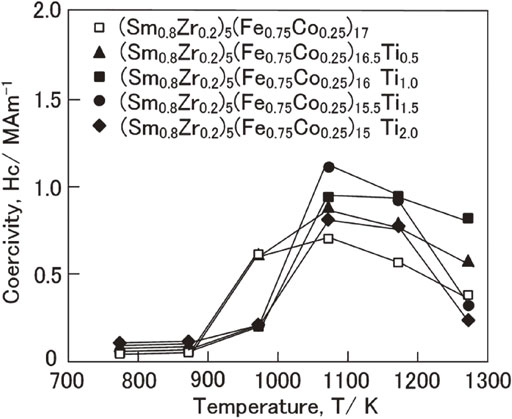
Dependence of the coercivity of the (Sm0.8Zr0.2)5(Fe0.75Co0.25)17−xTix (x = 0–2.0) melt-spun ribbons on the annealing temperature.
The hysteresis loops of the (Sm0.8Zr0.2)5(Fe0.75Co0.25)17−xTix (x = 0–2.0) melt-spun ribbons annealed at 1073 K for 1 h are shown in Fig. 8. The magnetization of the specimens in a maximal field of 25 kOe decreases as the Ti content increases, while the coercivity increases up to a Ti content of 1.5 then decreases with a further increase in Ti content. Unlike the as-quenched melt-spun ribbons, the annealed specimens show large hysteresis loops. However, these hysteresis loops are not smooth but contain kinks. This suggests that the specimens consist of two magnetic phases with different coercivity.

Hysteresis loops of (a) (Sm0.8Zr0.2)5(Fe0.75Co0.25)17, (b) (Sm0.8Zr0.2)5(Fe0.75Co0.25)16.5Ti0.5, (c) (Sm0.8Zr0.2)5(Fe0.75Co0.25)16Ti1.0, (d) (Sm0.8Zr0.2)5(Fe0.75Co0.25)15.5Ti1.5, and (e) (Sm0.8Zr0.2)5(Fe0.75Co0.25)15Ti2.0 melt-spun ribbons annealed at 1073 K. These loops were measured with a maximum magnetic field of 25 kOe.
The melt-spun ribbons annealed at 1073 K were examined in a thermomagnetic study to evaluate the differences in the coercivity values. The thermomagnetic curves of these specimens are shown in Fig. 9. Since it is known that the Sm5Fe17 phase exhibits high coercivity, we had assumed that the annealed specimens would consist of the Sm5Fe17-type phase. However, these annealed specimens did not consist of the Sm5Fe17-type phase but rather the SmFe3-type phase. This is attributed to the fact that the Sm5Fe17-type phase is a metastable phase whereas the SmFe3-type phase is a stable phase. The achieved high coercivity in the annealed melt-spun ribbons was therefore not due to the Sm5Fe17-type phase but to the SmFe3-type phase. However, the second phase was not clearly detected in the thermomagnetic study.

Thermomagnetic curves of (a) (Sm0.8Zr0.2)5(Fe0.75Co0.25)17, (b) (Sm0.8Zr0.2)5(Fe0.75Co0.25)16.5Ti0.5, (c) (Sm0.8Zr0.2)5(Fe0.75Co0.25)16Ti1.0, (d) (Sm0.8Zr0.2)5(Fe0.75Co0.25)15.5Ti1.5, and (e) (Sm0.8Zr0.2)5(Fe0.75Co0.25)15Ti2.0 melt-spun ribbons annealed at 1073 K.
In Sm–Fe system alloys, since the diffraction peaks of the Sm5Fe17 phase overlap those of the SmFe3 phase, it is difficult to distinguish these phases by ordinary XRD studies. Therefore, a further structural study was carried out by the SR-XRD in order to reveal the detailed structures of these specimens. The results are shown in Fig. 10. The crystalline phases determined by the SR-XRD data are summarized in Table 1. It was confirmed that all of the specimens consisted mainly of the SmFe3-type phase. In addition, the SR-XRD study revealed that the (Sm0.8Zr0.2)5(Fe0.75Co0.25)17, (Sm0.8Zr0.2)5(Fe0.75Co0.25)16.5Ti0.5, and (Sm0.8Zr0.2)5(Fe0.75Co0.25)16Ti1.0 specimens consisted of the Sm2Fe17-type phase together with the SmFe3 type and that the (Sm0.8Zr0.2)5(Fe0.75Co0.25)15Ti1.5 and (Sm0.8Zr0.2)5(Fe0.75Co0.25)15Ti2.0 specimens consisted of the SmFe2-type phase together with the SmFe3-type. This indicates that the amount of the Sm2Fe17-type phase in the specimens decreased as the Ti content increased but a further increase in the Ti content resulted in the formation of the SmFe2-type phase. Since the second phases such as the Sm2Fe17-type and SmFe2-type phases in the annealed specimens are magnetically soft, the observed high coercivities in the annealed melt-spun ribbons are considered to be due to the existence of the hard magnetic SmFe3-type phase. It has recently been reported that the substitution of Zr for Sm in the SmFe3 phase increased the coercivity.15,16) We believe that a specimen containing only the hard magnetic SmFe3-type phase will be able to be obtained by optimization of the annealing conditions.

SR-XRD patterns of (a) (Sm0.8Zr0.2)5(Fe0.75Co0.25)17, (b) (Sm0.8Zr0.2)5(Fe0.75Co0.25)16.5Ti0.5, (c) (Sm0.8Zr0.2)5(Fe0.75Co0.25)16Ti1.0, (d) (Sm0.8Zr0.2)5(Fe0.75Co0.25)15.5Ti1.5, and (e) (Sm0.8Zr0.2)5(Fe0.75Co0.25)15Ti2.0 melt-spun ribbon annealed at 1073 K.

In this study, (Sm1−xZrx)5(Fe0.75Co0.25)17 (x = 0–0.4) alloys were prepared by melt-spinning. As-quenched melt-spun ribbons of (Sm1−xZrx)5(Fe0.75Co0.25)17 (x = 0–0.4) alloys consisted of fully or partially amorphous phase and showed low coercivity. Annealing of the (Sm1−xZrx)5(Fe0.75Co0.25)17 (x = 0–0.4) alloys resulted in an increase in coercivity. The highest coercivity of 0.60 MAm−1 was achieved in the (Sm0.8Zr0.2)5(Fe0.75Co0.25)17 melt-spun ribbon after annealing at 1073 K. In order to increase the coercivity of the (Sm0.8Zr0.2)5(Fe0.75Co0.25)17 alloy, the (Sm,Zr)5(Fe,Co)17−xTi (x = 0–2.0) melt-spun ribbons were prepared. As-quenched melt-spun ribbons of (Sm,Zr)5(Fe,Co)17−xTi (x = 0–2.0) alloys showed low coercivity. The (Sm,Zr)5(Fe,Co)17−xTi (x = 0–0.5) specimens consisted of the Sm5Fe17-type phase together with the SmFe3-type phase, while the (Sm,Zr)5(Fe,Co)17−xTi (x = 1.0–2.0) specimens consisted of the SmFe3-type phase. Annealing of these melt-spun ribbons increased their coercivity regardless of the Ti content. It was found that the annealed melt-spun ribbons consisted mainly of the SmFe3-type phase. The (Sm,Zr)5(Fe,Co)15.5Ti1.5 melt-spun ribbon annealed at 1073 K for 1 h exhibited the highest coercivity of 1.11 MAm−1.
This work was supported by JSPS KAKENHI Grant Number 17K06776. This work was performed using the facilities of the Institute for Solid State Physics, The University of Tokyo. X-ray data were acquired at the NE1A beam line of KEK (2015G522).