Abstract
In this study, multilayer diamond-like carbon films 1 µm thick with different numbers of multilayer repetitions were deposited onto austenitic stainless steel SUS304 substrates using different source gases. The influence of the gas and the difference in the number of multilayer repetitions on the adhesion strength and wear resistance of the films was subsequently investigated. The samples were subjected to cross-sectional microstructure observations, elemental analysis by glow-discharge optical emission spectroscopy, nano-indentation tests, Rockwell indentation tests, friction and wear tests, and delamination tests. The nano-indentation tests showed that the films prepared using C2H2 gas were harder than those prepared using CH4 gas. In addition, irrespective of the gas used, the film hardness was improved when four layers rather than two layers were deposited. However, the hardness of the eight layers film decreased. The Rockwell indentation tests showed no improvement in adhesiveness when the gas or the number of multilayer repetitions was varied. The wear tests revealed that the friction coefficient of the films prepared using C2H2 gas was smaller than that of films prepared using CH4 gas. No difference was observed with increasing number of multilayer repetitions. The delamination tests showed that the distance until delamination of the films prepared using C2H2 gas was longer than that of the films prepared using CH4 gas. In addition, the distance until delamination was improved by changing the number of multilayer repetitions from two layers to four layers for both gases but decreased when the number of repetitions was extended to eight layers. In this study, the value of H/E (hardness/Young’s modulus) increased and various characteristics improved with increasing number of multilayer repetitions.

1. Introduction
Diamond-like carbon (DLC) has a mixture of sp3 bond regions corresponding to the diamond structure and sp2 bond regions corresponding to the graphite structure and also contains bonds with hydrogen. Moreover, its structure is amorphous; i.e., it lacks a specific crystal structure.1) Therefore, the hardness and electrical properties of DLC are similar to those of diamond, but its thermal conductivity is similar to that of graphite. In addition, DLC films exhibit excellent properties, including high hardness, a low friction coefficient, good wear resistance, and high corrosion resistance, which makes DLC films suitable for use in the field of tribology.2–10) However, the specific characteristics of DLC films differ greatly depending on the film-forming conditions and the operating environment. In recent years, researchers have attempted to develop super-lubricating and high-wear resistant films by exploiting changes in the chemical properties of the surface depending on the amount of hydrogen contained in DLC films.11) Several types of DLC films are known, including amorphous carbon (a-C), tetrahedral amorphous carbon (ta-C), hydrogenated amorphous carbon (a-C:H), and hydrogenated tetrahedral amorphous carbon (ta-C:H) films.1)
The high residual stress of DLC films is the main reason for their delamination and decreased durability. DLC films have high internal stress, and their high defect concentrations lead to poor adhesion between the substrate and the film. Because there is a large difference in the coefficient of thermal expansion between the DLC film and the substrate, thermal contraction due to large thermal stress leads to compressive residual stress.12,13) In addition, in the case of a substrate into which carbon easily diffuses, such as steel, the adhesion of the DLC film is further diminished by the diffusion of carbon into the substrate.14–16) Thus, introducing a metal interlayer with a coefficient of thermal expansion intermediate between those of the DLC film and the substrate will reduce the difference in coefficient of thermal expansion between the DLC film and its substrate, thereby reducing both the thermal stress and the diffusion of carbon into the substrate.17,18) In addition, the literature contains numerous reports that the adhesion is improved by introducing a DLC interlayer containing a metal element (Me-DLC interlayer) to reduce the internal stress of the DLC film.12,19) In the reported examples of a metal interlayer and a Me-DLC intermediate layer, metal elements that easily form carbides, such as Ti, Cr, W, and Si, are used.20–22) In these cases, an increase of the film hardness, a decrease of the friction coefficient, and an increase of the delamination distance were observed when the number of multilayer repetitions was increased and multiple intermediate layers were introduced.23–25) The stress has been reported to be relaxed with increasing number of interfaces.26) Sui et al. reported that the wear rate of the mating material was reduced and the friction and wear characteristics were improved in a multilayer DLC film compared with those in a DLC single layer and a CrN single layer.27) Maruno and Nishimoto have also reported that the apparent hardness and the friction and wear characteristics were improved by deposition of multilayer DLC films onto an Al alloy.28)
In this study, we investigated the effect of different gases and number of multilayer repetitions on adhesion strength and wear resistance by depositing multilayer DLC films onto SUS304 austenitic stainless steel using different source gases.
2. Experimental Procedure
2.1 Film deposition
As the experimental sample, ϕ25 mm SUS304 austenitic stainless steel was used. Prior to the deposition of a DLC coating, the surface of the steel was flattened using a lathe, roughly ground to #2000 with wet emery paper, and then buffed with 1.0 µm alumina powder to a mirror surface. A DLC film was then deposited onto the sample using the plasma-enhanced chemical vapor deposition (PECVD) technique. The sample was placed on the cathode rotating electrode plate, and CH4 gas, which was a reaction gas, was decomposed by glow discharge generated by applying 13.56 MHz high-frequency power between the sample and the anode electrode. A schematic of the PECVD apparatus (Shinko Seiki, ACV-1060D) is shown in Fig. 1. Prior to deposition, the sample was ultrasonically washed with acetone for 10 min. PECVD was carried out at a base pressure of 1.0 × 10⁻³ Pa and 443 K. As a pretreatment for the DLC coating, an Ar bombardment treatment was conducted for 10 min using Ar plasma generated with an applied bias of −340 V and at an operating pressure of 0.50 Pa. Table 1 and Table 2 show the processing conditions used in this study. Si-containing DLC (Si-DLC) was deposited as a soft layer using CH4 gas and tetramethylsilane (Si(CH3)4, TMS), DLC was deposited as a hard layer using CH4 gas or C2H2 gas, and the total film thickness was unified to 1 µm. Samples were prepared with two, four, or eight layers. The multilayer DLC films deposited using CH4 are denoted as two layers (CH4) four layers (CH4), and eight layers (CH4). The multilayer DLC films deposited using C2H2 are denoted as two layers (C2H2), four layers (C2H2), and eight layers (C2H2).
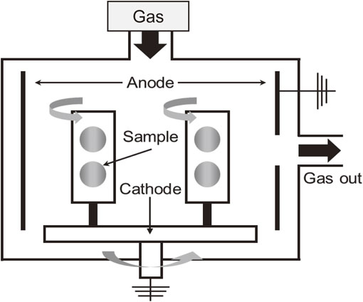

Table 1 Conditions during the CVD processes using CH4 gas.

Table 2 Conditions during the CVD processes using C2H2 gas.
The cross-sectional microstructures were observed to measure the thickness of the Si-DLC film and the DLC films prepared with different numbers of multilayer repetitions. The prepared sample was cut in the direction perpendicular to the deposited surface, embedded in a thermosetting resin, and finished to a mirror surface. The cross-sectional microstructure was observed by scanning electron microscopy (SEM, JEOL, JSM-6060LV). The acceleration voltage was 15 kV.
To confirm the formation of a multilayer structure, elemental analysis was conducted using glow-discharge optical emission spectroscopy (GD-OES, HORIBA, GD-Profiler2). The conditions for GD-OES were a sputtering mark diameter of 4 mm, discharge pressure of 600 Pa, and output of 35 W. The measured elements were Si, C, and Fe.
To evaluate the hardness of the films deposited under each condition, nanoindentation tests were performed using an ultrafine indentation hardness tester (Elionix, ENT-2100). In the present study, a precision instrument that measures and controls ultra-low test force and minute displacement was used; the diamond indenter was pressed into the sample placed on the stage and the load and displacement were measured. The mechanical properties were calculated from the resultant curve. In addition, when measuring the hardness of the thin film itself, to prevent the hardness of the sample from affecting the measurement result, the load was selected such that the value obtained by dividing the indentation depth by the film thickness was 0.1 or less. These tests were run in triplicate for each sample, and the averages were used to determine the hardness H and Young’s modulus E. Equations (1) and (2) were used to calculate H and E, respectively.
| \begin{equation}
\text{Indentation hardness:}\ H_{\text{it}} = F_{\text{max}}/A_{\text{p}}
\end{equation}
| (1) |
where
Fmax is the maximum test force (N), and
Ap is the projected area (m
2) where the indenter and the test piece are in contact.
| \begin{equation}
\text{Indentation Young's modulus:}\ E_{\text{it}} = \frac{1 - \nu_{\text{s}}^{2}}{E_{\text{r}}} - \frac{1 - \nu_{\text{i}}^{2}}{E_{\text{i}}}
\end{equation}
| (2) |
where ν
s is the Poisson’s ratio (0.02) of the sample, ν
i is the Poisson’s ratio of the indenter (0.07),
Ei is the Young’s modulus of the indenter (1140 GPa), and
Er is the reduced elastic modulus due to indentation contact. The
E and
H of the DLC films were determined using the Oliver–Pharr equations.
29) The Poisson’s ratio was used for the DLC film to calculate
E.
A Rockwell indentation test was performed to compare the adhesion strength between the DLC films and the samples. A diamond indenter for C scale was pressed at 1471 N (150 kgf), and the plastic deformation region formed around the indentation was observed using an optical microscope (Keyence, VHX-200). Adhesion strength was evaluated by ranking each with HF1 to HF6 of the VDI 3198 standard.30) HF1 corresponds to only a few cracks around the indentation and is considered to have good adhesion. HF6 corresponds peeling of the entire film around the indentation; such samples were judged to exhibit poor adhesion.
Wear tests were performed according to standard ISO 18535 to evaluate abrasion resistance and durability. The tests were conducted on a pin-on-disk tribometer (CSM Instruments, Tribometer) using a 6.35 mm-diameter Al2O3 ball as the counter material. All samples were ultrasonically cleaned in acetone for 10 min and dried in an oven for 30 min at 393 K. The tests were carried out at a laboratory temperature of ±2 K and a relative humidity of 50 ± 10% using a sliding speed of 0.1 m/s and a sliding load of 5 N with a wear radius of 7 mm. The sliding distance was 1000 m, and the wear rate Wsample of the wear marks remaining on the surface of the sample after the test was calculated. The wear volume of the sample was obtained by measuring the wear width and wear depth using a surface roughness measuring instrument (Kosaka Seisakusho, SE300), and calculating the wear volume according to eq. (3):
| \begin{equation}
V_{\text{sample}} = 2\pi \cdot R \cdot S\,(\text{mm}^{3})
\end{equation}
| (3) |
where
R is the wear scar radius (
R = 7 mm),
S is the wear area of the sample surface (mm
2) and was calculated by
eq. (4):
| \begin{equation}
S = \frac{wd}{2}
\end{equation}
| (4) |
where
w is the wear width (mm) and
d is the wear depth (mm).
| \begin{equation}
W = \frac{V}{FL}
\end{equation}
| (5) |
Here, W is the wear rate (mm2/N), F is the applied load (N), and L is the sliding distance (m). In addition, tests were conducted until delamination; the delamination distance of the DLC film was subsequently evaluated. The delamination load was set to 3.0 N, and delamination was considered to occur when the delamination load exceeded 3.0 N.
3. Results and Discussions
The cross-sectional microstructures of multilayer DLC films with different numbers of multilayer repetitions were observed to measure the thickness of the Si-DLC interlayer and that of the DLC film. Figure 2 shows a SEM micrograph of the cross-sectional microstructure. The film thickness of the Si-DLC and DLC was approximately 1 µm in each sample. This observed film thickness was used as the condition in the nanoindentation tests. However, because we could not determine whether it had a multilayer structure, elemental analysis was performed using GD-OES.

Figure 3 shows the GD-OES results. Figure 3(a) shows a multilayer DLC of two layers deposited using CH4, (b) shows four layers, and (c) shows eight layers. In addition, Fig. 3(d) shows the multilayer DLC with two layers deposited using C2H2, (e) shows four layers, and (f) shows eight layers. In Fig. 3(a) and (d), the Si peak was observed once, along with a C peak. Thus, these results show that Si-DLC and DLC were formed into two layers. In the results in Fig. 3(b) and (e), the Si peak was confirmed twice and the C peak was also confirmed. Thus, Si-DLC and DLC were formed in four layers, where Si-DLC and DLC were deposited in alternating fashion. In the results in Fig. 3(c) and (f), the Si peak was confirmed four times and the C peak was also confirmed. Thus, Si-DLC and DLC were deposited in eight layers in alternating fashion.

The nano-indentation tests were conducted to evaluate the hardness of the multilayer DLC films deposited under each condition. Figure 4 shows the typical load–displacement curves for the film, and Table 3 shows the hardness values and Young’s moduli calculated from the curves. The nano-indentation tests revealed that the hardness of the thin film films with two, four, and, eight multilayer repetitions using CH4 gas was 17.4, 18.1, and 16.9 GPa, respectively. The hardness of the thin films with two, four, and, eight multilayer repetitions using C2H2 was 18.9, 19.3, and 17.2 GPa, respectively. In both cases, prepared using four multilayer repetitions exhibited the highest hardness. This result is attributed to the number of interfaces between the DLC film and the sample increasing with increasing number of multilayer repetitions to form a multilayer structure, the energy generated by high internal stress being dissipated, the adhesion strength increasing, and the apparent hardness increasing.26) However, in the cases, the hardness decreased when the number of multilayer repetitions was eight. We speculate that the film hardness decreased because the thickness of the film per layer was small and the Si-DLC film under the uppermost film layer was affected. Other researchers have reported that strength of the film increases with increasing value H/E obtained by dividing the hardness H by the Young’s modulus E.28,31) We found that the value of H/E increased and the film characteristics were improved with increasing number of multilayer repetitions.


Table 3 Hardness, Young’s modulus, and H/E values of multilayer Si-DLC/DLC films.
Rockwell indentation tests were performed to compare the adhesion strength between the multilayer DLC and the samples; the results are shown in Fig. 5. After the indentation test, delamination of the film around the indentation surrounded by cracks was observed in each case, and good adhesion (HF2) was shown. This result indicates that no change occurred in the multilayer structure because the film thickness was as small as 1 µm. However, the adhesion of the C2H2 films became HF 1 when the number of multilayer repetitions was increased. We attributed this result to the C2H2 films being harder and possessing greater internal stress than the CH4 films; however, the internal stress was dissipated with increasing film thickness, which led to improved adhesion.26,32)

Wear tests were carried out for the purpose of evaluating the wear resistance. Figure 6 shows the friction transition curve for the tests with a sliding distance of 1000 m. The result in Fig. 6 show that, among samples prepared using the same gas, the value of the friction coefficient μ did not substantially change irrespective of the number of repetitions of film formation. Other authors have reported no difference in the friction coefficients of DLC films prepared using the same gas.24) Likewise, in the present study, no difference is observed in the friction coefficients of DLC films prepared using the same gas. However, the value of the friction coefficient μ was smaller in the samples prepared using C2H2 gas than in the samples prepared using CH4 gas. We attribute this difference to the films prepared using C2H2 gas being harder and is less likely to wear than the films prepared using CH4 gas and therefore exhibiting a smaller coefficient of friction. Since plasma generated by C2H2 gas contains two carbon atoms, when ions collide with the substrate surface, the energy of each carbon atom is reduced to about 1/2, and the sp2 bond formation is suppressed. On the contrary, there is a report that the ion energy having only one carbon atom is large in the plasma of CH4 gas, which promotes increases in sp2 bonding and the desorption of hydrogen, and enables the formation of a more graphite-like film. It was considered that the sample formed with C2H2 gas had many sp3 bonds, which led to increased hardness, and it was considered that the improved hardness affected the decrease in friction coefficient.32–35)

Figure 7 shows the wear tracks after the friction wear test. In the films prepared using CH4 gas, the wear width was narrowed with increasing number of multilayer repetitions from two; thus, the friction and wear characteristics were improved. By contrast, no change was observed in the films prepared using C2H2 gas. However, in both cases, the wear width was substantially widened in the samples with eight layers. We considered that the characteristics were improved in the samples prepared using CH4 because the energy was dissipated with increasing number of multilayer repetitions. In the case of the samples prepared using C2H2, the characteristics were also improved and there was not much difference in the process of abrading the uppermost film.26,28,32) Further, because the wear width of the eight layers was wide, the characteristics were adversely affected if the thickness of the film per layer was too small.36) Figure 8 shows the wear rates of the samples after the tests conducted at a sliding distance of 1000 m. The wear rates shown in Fig. 8 indicate a similar wear-track width trend as observed in Fig. 7. The results in Fig. 8 show that, when the number of multilayer repetitions is increased from two to four, the wear rate decreases and the friction and wear characteristics of the samples deposited using CH4 are improved. However, the wear rate significantly increased when the number of layers was increased to eight. By contract, in the samples deposited by using C2H2, the wear rate did not change even when the number of multilayer repetitions was increased and the number of layers was increased from two to four. However, the wear rate increased substantially when the number of layers was increased to eight layers. These results show that the friction and wear characteristics are improved by increasing the number of multilayer repetitions; however, if the thickness of the film per layer becomes too small, the force applied per layer will increase and the energy will be dissipated.26,28) We speculated that the frictional wear characteristics are substantially deteriorated because of the insufficient friction.


Figure 9 shows the results of friction and wear tests until delamination. The results in Fig. 9, show that, for all the samples prepared using CH4 gas and C2H2 gas, when the number of multilayer repetitions was increased to four, the sliding distance was longer than that of the two films prepared with two repetitions. In addition, the sliding distance was substantially reduced in the samples prepared with eight repetitions. We speculated that the increased number of interfaces dissipates the applied energy and improves the friction and wear characteristics, as described in the discussion of the friction and wear tests. However, the sample with eight layers exhibited a small film thickness per layer and wear was promoted without the samples being able to dissipate the energy.26,28) The sliding distance was improved for the samples prepared using C2H2 gas compared with that for the samples prepared using CH4 gas. We speculated the sliding distance was extended because the film of the sample prepared using C2H2 gas was harder and less likely to wear.32–35)

4. Conclusion
In this study, PECVD was used to deposit a 1 µm total multilayer DLC film onto SUS304 with Si-DLC and DLC films deposited in alternating fashion. Furthermore, the effect on the properties of each multilayer DLC film prepared using different source gases (CH4 and C2H2) was investigated. The adhesion strength, wear resistance, and durability of the DLC films were also investigated. The tests revealed the following:
-
(1)
The nanoindentation tests showed that the hardness of the films with four layers exhibited the greatest hardness irrespective of whether the samples were prepared using CH4 gas or C2H2 gas. However, in all of the samples, the hardness decreased when the number of multilayer repetitions was increased to eight. We found that the value of H/E increased and the film characteristics were improved with increasing number of multilayer repetitions.
-
(2)
In the Rockwell indentation tests, samples prepared using CH4 gas exhibited delamination of the film around the indentation surrounded by cracks and good adhesion (HF2) was observed. In samples prepared using C2H2 gas, when the number of multilayer repetitions was four or eight, only cracks were observed, and good adhesion (HF1) was observed.
-
(3)
The friction and wear tests showed that the value of the friction coefficient μ did not substantially change in the samples prepared using the same gas, even when the number of layers was varied. Also, the friction coefficient μ was smaller in the samples prepared using C2H2 gas than in those prepared using CH4 gas.
-
(4)
The delamination tests showed that, in all of the samples prepared using CH4 gas and C2H2 gas, when the number of multilayer repetitions was increased to four, the sliding distance was longer than that of samples with two layers. Moreover, the sliding distance was substantially reduced in the samples with eight layers. We also found that the samples prepared using C2H2 gas exhibited longer sliding distances than those prepared using CH4 gas.
Acknowledgments
The authors would like to thank Mr. Satoshi Hattori from the Kyoto Prefectural Technology Center for Small and Medium Enterprises, Japan for the nano-indentation tests.
REFERENCES
- 1) J. Robertson: Prog. Solid State Chem. 21 (1991) 199–333.
- 2) A. Erdemir, F.A. Nichols, X.Z. Pan, R. Wei and P. Wilbur: Diamond Related Materials 3 (1994) 119–125.
- 3) J. Deng and M. Braun: Diamond Related Materials 4 (1995) 936–943.
- 4) C. Donnet and A. Grill: Surf. Coat. Tech. 94–95 (1997) 456–462.
- 5) C. Donnet: Surf. Coat. Tech. 100–101 (1998) 180–186.
- 6) T. Morita, K. Andatsu, S. Hirota, T. Kumakiri, M. Ikenaga and C. Kagaya: Mater. Trans. 54 (2013) 732–737.
- 7) S.-H. Chang, W.-C. Wu, K.-T. Huang and C.-M. Liu: Mater. Trans. 58 (2017) 806–812.
- 8) S. Takesue, H. Akebono, M. Furukawa, S. Kikuchi, J. Komotori and H. Nomura: Mater. Trans. 59 (2018) 642–647.
- 9) H. Maruno and A. Nishimoto: J. Japan Inst. Met. Mater. 83 (2019) 82–86.
- 10) T. Aizawa, T. Shiratori, T. Yoshino and T. Inohara: Mater. Trans. 61 (2020) 244–250.
- 11) S. Neuville and A. Matthews: Thin Solid Films 515 (2007) 6619–6653.
- 12) P. Wang, X. Wang, T. Xu, W. Liu and J. Zhang: Thin Solid Films 515 (2007) 6899–6903.
- 13) C. Wei, Y.S. Wang and F.C. Tai: Diamond Related Materials 18 (2009) 407–412.
- 14) C.L. Chang and D.Y. Wang: Diamond Related Materials 10 (2001) 1528–1534.
- 15) P.S. Weiser, S.P. Rawer, R.R. Manory, A. Hoffman, P.J. Evans and P.J.K. Patersone: Surf. Coat. Tech. 71 (1995) 167–174.
- 16) E.R. Kupp, W.R. Drawl and K.E. Spear: Surf. Coat. Tech. 68–69 (1994) 378–383.
- 17) C. Wei and J. Yen: Diamond Related Materials 16 (2007) 1325–1330.
- 18) F. Cemin, L.T. Bim, C.M. Menezes, M.E.H.M. Costa, I.J.R. Baumvol, F. Alvarez and C.A. Figueroa: Surf. Coat. Tech. 283 (2015) 115–121.
- 19) Y. Pauleau and F. Thiery: Surf. Coat. Tech. 180–181 (2004) 313–322.
- 20) M.D. Bentzon, K. Mogensen, J.B. Hansen, C.B. Hansen, C. Trholt, P. Holiday and S.S. Eskildsen: Surf. Coat. Tech. 68–69 (1994) 651–655.
- 21) J.Y. Jao, S. Han, C.C. Yen, Y.C. Liu, L.S. Chang, C.L. Chang and H.C. Shih: Diamond Related Materials 20 (2011) 123–129.
- 22) Z. Fu, C. Wang, W. Zhang, W. Wang, W. Yue, X. Yu, Z. Peng, S. Lin and M. Dai: Mater. Des. 51 (2013) 775–779.
- 23) W. Zhang, A. Tanaka, B.S. Xu and Y. Koga: Diamond Related Materials 14 (2005) 1361–1367.
- 24) F.D. Duminica, R. Belchi, L. Libralesso and D. Mercier: Surf. Coat. Tech. 337 (2018) 396–403.
- 25) C. Guo, Z.L. Pei, D. Fan, J. Gong and C. Sun: Diamond Related Materials 60 (2015) 66–74.
- 26) E. Kusano, N. Kikuchi and A. Kinbara: J. Surf. Finish. Soc. Jpn. 51 (2000) 380–383.
- 27) X. Sui, J. Liu, S. Zhang, J. Yang and J. Hao: Appl. Surf. Sci. 439 (2018) 24–32.
- 28) H. Maruno and A. Nishimoto: Surf. Coat. Tech. 354 (2018) 134–144.
- 29) N. Dwivedi, S. Kumara and H.K. Malik: Appl. Surf. Sci. 257 (2011) 9953–9959.
- 30) C.C. Chen and F.N. Hong: Appl. Surf. Sci. 243 (2005) 296–303.
- 31) A. Leyland and A. Matthews: Wear 246 (2000) 1–11.
- 32) J. Choi, T. Hibi, A. Furuno, M. Kawaguchi and T. Kato: J. Jpn. Soc. Tribologists 62 (2017) 228–235.
- 33) C.P. Chen and A.H. Tan: Surf. Eng. 27 (2011) 151–157.
- 34) U. Rittihong, H. Akasaka, C. Euaruksakul, M. Tomidokoro, N. Kamonsuttipaijit, H. Nakajima, R. Supruangnet, C. Rojviriya, A. Chingsungnoen, P. Poolcharuansin, N. Ohtake and S. Tunmee: Radiat. Phys. Chem. 173 (2020) 108944.
- 35) M. Suzuki, S. Hironaka, H. Toyoshima, T. Tokoroyama and A. Tanaka: J. Surf. Sci. Soc. Jpn. 25 (2004) 232–237.
- 36) C. Guo, Z. Pei, J. Gong, C. Sun, S. Lin and Q. Shi: Diamond Related Materials 92 (2019) 187–197.
