Abstract
In this study, the surface of industrial pure iron was treated with atmospheric-controlled induction heating fine particle peening (AIH-FPP) using mechanical coating (MC) particles of carbon/steel obtained by mixing carbon powder and fine steel particles using mechanical milling. The surface modification effect and the mechanism of its effect were examined and considered by analyzing of the treated surface. Results showed that a modified layer in which carbon elements were diffused was formed near the treated surface by the AIH-FPP treatment using MC particles. In addition, by examining the influence of the treatment conditions on the formation of the modified layer by the design of experiments, the treatment temperature showed the most significant influence among the treatment temperature, peening time, and gas flow rate. The higher the treatment temperature, the deeper the carbon diffused layer. In addition, when treated at ≥1273 K, the microstructure near the surface became pearlite, and Vickers hardness increased. The time required for carbon diffusion in the AIH-FPP carburizing process using MC particles of carbon/steel was approximately the same as that of a general carburizing treatment using a reactive gas. In the AIH-FPP carburizing process, carbon is considered to be transferred from the particles to the surface, and the grain boundaries and dislocations increased by fine particle peening (FPP) are used as channels to diffuse inside the specimen. This mechanism is entirely different from the conventional carburizing methods.
This Paper was Originally Published in Japanese in J. Soc. Mater. Sci., Jpn. 71 (2022) 787–794.
1. Introduction
Carburization can improve wear resistance and fatigue properties of materials while maintaining their toughness. However, practical gas carburizing has limitations, such as the generation of carbon monoxide during the reaction process and the risk of fire from the oil used for quenching. Moreover, this process is time-consuming, which is challenging from the viewpoint of energy consumption. To solve these problems, the authors focused on atmospheric-controlled induction-heating fine particle peening (AIH-FPP) and studied the development of a novel carburization technique using this treatment process.
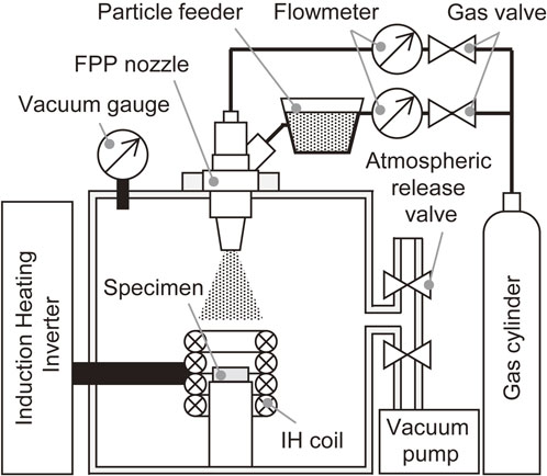
AIH-FPP is a surface modification process that combines fine particle peening (FPP)1,2) and induction-heating.3,4) Figure 1 shows the configuration of the treatment system. During AIH-FPP, fine particles with a diameter less than 200 µm were shot at a high velocity onto an induction-heated metal under an arbitrary atmosphere.5–8)
The authors treated structural steels using an AIH-FPP system with fine chromium, nickel, or molybdenum particles. Corrosion resistance and electrochemical characteristics that were similar or superior to those of stainless steel were achieved at the treated surfaces within a few minutes.9,10) Combustion synthesis reactions occurred when aluminum or titanium particles were used, and intermetallic compound layers with high wear resistance and high-temperature oxidation resistance were formed.11,12) When high-speed tool steel particles with high hardness were shot to the surfaces of structural steels heated to recrystallization temperatures, surface layers containing fine grains with diameters of several micrometers were created owing to dynamic recrystallization, which improved the fatigue properties of AIH-FPP-treated steel.13) This procedure can be applied to materials that are difficult to refine using only thermal treatments.14) Recently, the authors used this system to demonstrate the formation of a nitrogen compound layer and diffusion layer by blowing nitrogen gas onto an induction-heated titanium alloy under nitrogen atmosphere for approximately 3 min.15–19)
According to previous studies, AIH-FPP using carbon powder is expected to transfer carbon to the treated surfaces, diffuse it into the specimens, and achieve carburization. Moreover, quenching may be achieved by a single process because the specimens are rapidly cooled by gas blowing after heating. In this study, fine steel particles coated with carbon powder were prepared via mechanical milling. AIH-FPP using the particles was performed under various conditions, and the carbon diffusion behavior and accompanying microstructural changes were evaluated by analyzing the prepared specimens. To quantitatively examine the influence of the process parameters on carbon diffusion, a design of the experiment was introduced. The formation mechanism of the carbon diffusion layer during AIH-FPP is discussed based on the experimental results.
2. Evaluation of the Treatment Parameters by Design of Experiment
Several process parameters affect the surface characteristics of AIH-FPP-treated specimen. Therefore, the design of the experiment was introduced so that their influences could be quantitatively evaluated.
2.1 Selection of the treatment parameters and allocation to an orthogonal array
AIH-FPP includes various treatment parameters, such as the treatment temperature (surface temperature of the specimen), heating time, gas flow rate/velocity during peening, size, hardness, chemical composition of the shot particle, peening time, and particle supply rate. In this study, the authors focused on the treatment temperature, peening time, and gas flow rate during peening, and quantitatively evaluated their effects on the characteristics of the treated surface using the design of the experiment. The maximum value of the Vickers hardness measured at the cross section of the specimen and thickness of the modified layer measured from the optical micrographs were selected as the objective characteristics. These are the indices used to quantitatively estimate the influence of the factors.
Table 1 lists the levels of these three factors. The treatment temperature was set as the A3 transformation temperature of the pure iron used as the specimen, and the values were larger or smaller, namely 1173 K (below the transformation temperature), and 1223 K and 1273 K (above the transformation temperature), respectively. Based on previous studies,7,14,16) the peening times were determined to be 15, 30, and 45 s. Considering the capacity of the flow meter used in this study, the gas flow rate levels were chosen as 100, 150, and 200 L/min.
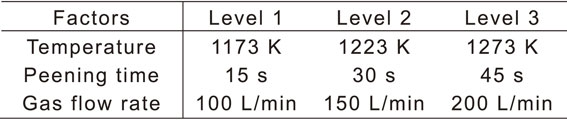
Table 1 Factor levels for design of experiment.
Table 2 lists an orthogonal array with the factor levels. Orthogonal arrays enable the calculation of the error variance without repetitive experiments by allocating experimental errors to the columns. This study used the L9(34) orthogonal array and allocated experimental errors to the third column. Based on this orthogonal array, AIH-FPP was performed under nine conditions and the obtained results were analyzed.
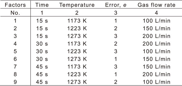
Table 2 L9(34) orthogonal array with factor levels.
Industrial pure iron with a carbon concentration lower than 0.02 wt% was used to easily observe the behavior of carbon diffusion by AIH-FPP. The material was machined into a disk-shaped specimen whose diameter and thickness were 15 mm and 4 mm, respectively. One end of the surface was polished with emery paper (∼#1200) and subjected to AIH-FPP.
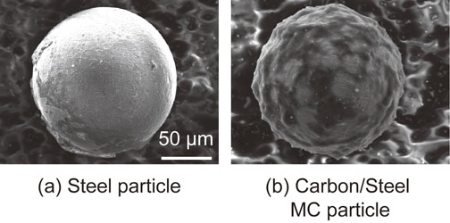
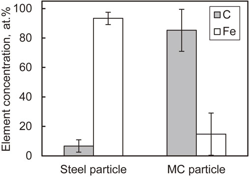
The carbon powder and steel particles were mechanically milled under the conditions determined by the preliminary experiment (Table 3), and the prepared particles were used as shot particles. The coarsened particles and remaining carbon powder were removed by sieving and classifying the particle diameters between 90 and 125 µm after mechanical milling. Henceforth, these particles are referred to as carbon/steel mechanical coating (MC) particles.20) They were prepared because the specific gravity of the carbon powder was too low to be used as a shot particle. Figure 2 shows a scanning electron microscopy (SEM) image of the carbon/steel MC particles whose appearance differs from that of the untreated steel particles. Figure 3 shows the Fe and C elemental concentrations measured at the surfaces of the particles using energy dispersive X-ray spectroscopy (EDX). The value in this figure was obtained such that the sum of Fe and C elemental concentrations was 100%. The carbon/steel MC particles contained higher concentration of C than untreated steel particles which indicates that carbon powder was coated on the surfaces of the steel particles.
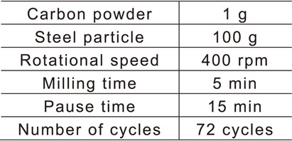
Table 3 Mechanical milling conditions for carbon/steel MC particles.
AIH-FPP was performed using the prepared particles under the conditions listed in Table 4. The temperature, peening time, and gas flow rate listed in this table are consistent with those listed in Table 1. AIH-FPP involves the following procedures. The chamber was evacuated to approximately 0.05 MPa, and nitrogen gas with a purity of 99.99% was supplied until atmospheric pressure was reached. This procedure, which was repeated twice, reduced oxygen concentration inside the chamber and created a nitrogen atmosphere inside the chamber. Subsequently, as shown in Fig. 4, the temperature of the specimen was increased for 10 s while maintaining the prescribed gas flow rate. The carbon/steel MC particles were shot for a prescribed time while the temperature was maintained. Subsequently, the specimen was cooled to room temperature using a blowing gas after completion of the heating process. The power of the induction-heating unit for temperature control was determined using a thermocouple attached to the specimen surface and a preliminary experiment was performed.
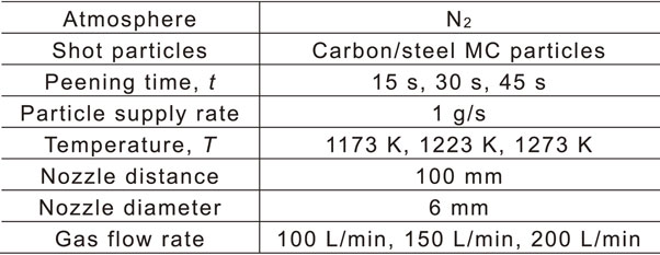
Table 4 AIH-FPP conditions.
Figure 5 shows the cross-sectional distribution of the Vickers hardness for each specimen. The Vickers hardness was measured under a force of 0.98 N and holding time of 20 s. The broken line indicates the hardness of the untreated specimen. Although the hardness of specimens 6 and 8 increased near the surfaces, those of the other specimens did not increase significantly. Compared with the hardness of the untreated specimen, all specimens treated via AIH-FPP exhibited decreased hardness at depths greater than 100 µm because of heating.
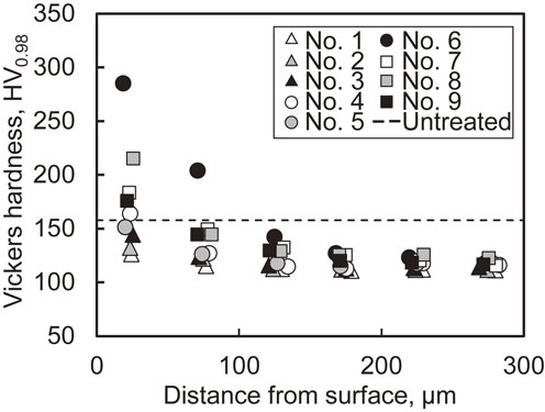
Figure 6 shows the optical micrographs obtained after polishing the longitudinal sections of the specimens to a mirror finish and etching them using nital. The gray region observed at the specimen surface corresponds to the nickel plating layer, which protects the fine asperities at the surfaces. A dark region was observed near the treated surfaces, except for specimens 1 and 2. This microstructure was fine pearlite, although a clear layered structure could not be identified. Therefore, owing to AIH-FPP using carbon/steel MC particles, diffused carbon is expected near the surface.
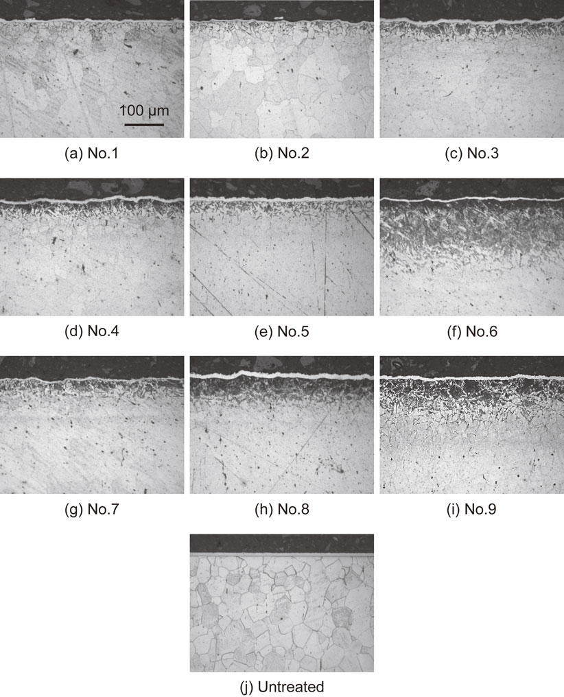
Table 5 lists the measured values of the maximum Vickers hardness at the cross-sections of the specimens and the thickness of the modified layer, which were selected as the objective characteristics. Figure 7 presents the response graphs that depict the effects of each factor on the objective characteristics. i) The maximum values of the Vickers hardness and thickness of the modified layer increased with the treatment temperature. ii) The peening time exhibited positive correlation with the maximum value of the Vickers hardness and thickness of the modified layer from 15 s to 30 s. However, it did not affect the increase in the values of the objective characteristics when it was prolonged to 45 s. iii) The gas flow rate did not significantly affect the maximum value of Vickers hardness and the thickness of the modified layer. Therefore, the treatment temperature significantly affected carbon diffusion qualitatively.
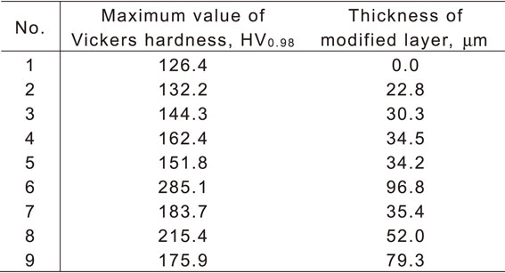
Table 5 Arrangement of responses.
Analysis of variance was performed to quantify the effects of each factor and the corresponding results are presented in Table 6. The variance ratio F0 in the table was calculated by dividing the variance of each factor by the variance of the error. When the degrees of freedom of each factor and error were 2, the factor whose F0 exceeded 19.00 exhibited a statistically significant difference. Therefore, the factors with significant effects did not exist, as shown in the table.
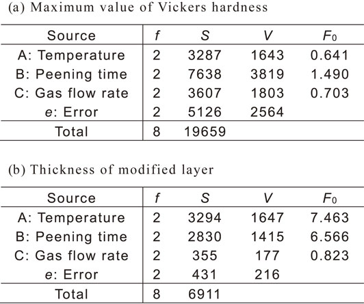
Table 6 Analysis of variance. (f: Degree of freedom, S: Sum of squares, V: Variance, F0: Variance ratio)
Subsequently, the factors whose F0 was lesser than 1 and effects were considered to be errors were pooled to the error. The analysis of variance was performed again with the increased degree of freedom for the error and improved accuracy of analysis. In particular, when the maximum Vickers hardness was analyzed, the treatment temperature and gas flow rate were considered to be errors. In the case of the thickness of the modified layer, the gas flow rate was considered to be an error. Table 7 presents the results of this study. Table 7(a) lists the results of the objective characteristics of the maximum Vickers hardness. Because the degree of freedom of error (e′) was 6, the factors with F0 ≥ 5.14 were significant. However, the factors that had a statistically significant effect on the objective characteristic did not exist which indicates that the factors that significantly affected the maximum Vickers hardness value were not among those examined in this study. However, when the objective characteristics were set as the thickness of the modified layer, the degrees of freedom of error (e′) were 4, and factors with F0 over 6.94 were significant. Therefore, treatment temperature and peening time significantly affected the objective characteristics.

Table 7 Analysis of variance. (f: Degree of freedom, S: Sum of squares, V: Variance, F0: Variance ratio, S′: Net sum of squares, ρ: Contribution rate, *: 5% significant)
The results presented above quantitatively indicated that the factors analyzed in this study did not significantly affect the maximum Vickers hardness, whereas the treatment temperature and peening time significantly affected the thickness of the modified layer. However, the response graph (Fig. 7) indicates that the effect of peening time qualitatively saturated for approximately 30 s, and carbon diffusion did not progress with peening time. Therefore, in the next section, we examine the effect of treatment temperature on the carbon diffusion behavior in detail.
3. Effect of the Treatment Temperature on the Carbon Diffusion Behavior
The treatment temperature was varied in the range of 1073–1473 K, and its effect on carbon diffusion behavior was evaluated.
3.1 Experimental procedure
The material and shot particles were industrial pure iron and carbon/steel MC particles, respectively, which were the same as those used in the previous section. AIH-FPP was performed at five different temperatures (Table 8). According to the design of the experiment, the gas flow rate was expected to have lesser influence; it was determined to be 130 L/min based on the capacity of the flow meter used. The thermal history during treatment was the same as that shown in Fig. 4.
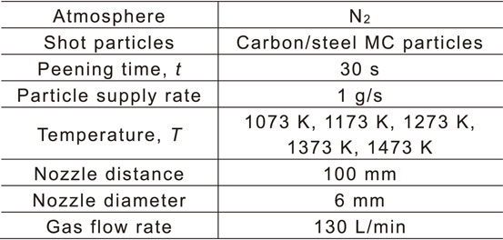
Table 8 AIH-FPP conditions.
SEM observations and EDX analyses were performed on the surfaces of specimens treated with AIH-FPP. The carbon diffusion behavior inside the specimen was evaluated via Vickers hardness distribution and elemental analysis using an electron probe micro-analyzer (EPMA). The microstructure near the surface was observed using an optical microscope and SEM after etching with 3% nital solution. The Vickers hardness was measured with a force of 0.98 N and holding time of 20 s, which are the same as those in Section 2.
3.2 Results and discussion
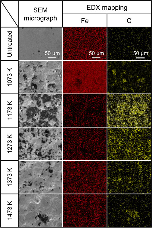
Figure 8 shows SEM micrographs of the treated surfaces and corresponding EDX maps of Fe and C. The SEM micrographs indicate the formation of asperities at the treated surfaces owing to the collision of particles irrespective of the treatment temperature. The elemental maps reveal the presence of C on the surfaces of the AIH-FPP-treated specimens which indicates that the carbon powder contained in the carbon/steel MC particles is transferred to the surfaces treated by AIH-FPP.
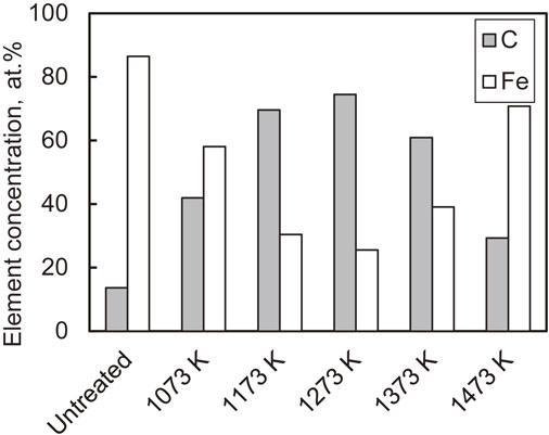
The effect of the treatment temperature on the elemental concentration of the treated surface was examined by measuring the elemental concentration using EDX. The corresponding results are shown in Fig. 9. The value in this figure was obtained such that the sum of Fe and C elemental concentrations was 100%. C was detected on the surfaces of the AIH-FPP-treated specimens irrespective of the treatment temperature. The ratio of C was maximum at 1273 K and decreased with increasing treatment temperatures because the carbon transferred to the surface diffused inside the specimen at high temperatures.
This was confirmed by measuring the distribution of the concentration of C in the longitudinal sections of the specimens using EPMA. The results are shown in Fig. 10. C was detected on the outermost surface of the untreated specimen, which was attributed to the phenol resin used to fix the specimen. The distributions of the specimen treated below 1173 K were the same as those of the untreated specimen, which demonstrated that carbon did not diffuse inside the specimen. In contrast, at treatment temperatures above 1273 K, elemental C was detected at a depth of 150–200 µm. These results suggest the formation of a carbon diffusion layer near the surfaces treated by AIH-FPP using carbon/steel MC particles above 1273 K.

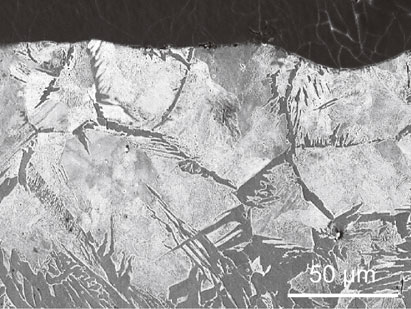
The microstructure in the longitudinal section near the surface revealed the effect of diffused carbon on the microstructure. Figure 11 shows the results obtained using an optical microscope. Below 1173 K (Fig. 11(b), (c)), the grains were refined at the outermost surfaces because dislocations were introduced by FPP, and dynamic recrystallization occurred.13,14) Microstructural changes owing to carbon diffusion were not observed. However, above 1273 K (Fig. 11(d)–(f)), modified layers with microstructural changes were formed to a depth of 100–150 µm because carbon diffused near the surfaces of the specimens via AIH-FPP, resulting in microstructural changes to pearlite. This was also observed in the SEM micrograph of the longitudinal section of the specimen treated at 1473 K, as shown in Fig. 12.
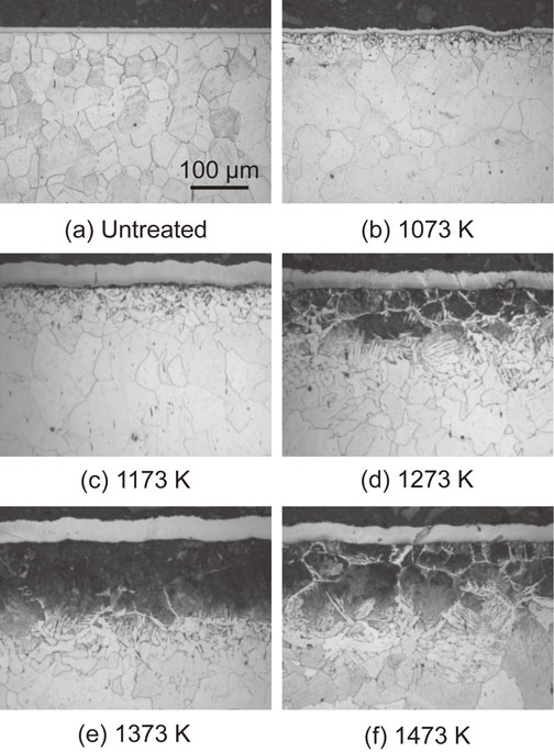
Figure 13 shows the cross-sectional distributions of the Vickers hardness. The hardness of the specimens treated below 1173 K was lower than that of untreated specimens. This was because, in addition to the effect of heating, carbon did not diffuse into the specimens. When the treatment temperature exceeded 1273 K, the hardness increased above 200 HV to a depth of approximately 100 µm from the surface. This value is close to the hardness of pearlite (approximately 250 HV), and the depths with increased hardness are consistent with the depth-detected C element (Fig. 10) and altered microstructure (Fig. 11(d), (e), (f)). Therefore, the hardness increased in this region owing to the transformation of the microstructure to pearlite by AIH-FPP.

In this study, because pure iron with low carbon concentration and poor hardenability was used to easily observe the diffusion behavior of carbon, the martensite transformation at the surface layer where carbon diffuses was not observed. To achieve carburization using AIH-FPP, steel with better hardenability should be used as the treated material, and the cooling rate should also be evaluated.
4. Mechanism of Carbon Diffusion
Gas, solids, liquids, and vacuum carburizing have already been utilized practically. In these processes, the sources of carbon are gaseous hydrocarbon such as propane and butane, charcoal, and sodium cyanide, and hydrocarbon gases such as methane and propane, respectively. Although the carbon supply sources vary with the technique used, direct reactions between the carbon supply sources and treated parts do not occur in all conventional carburizing processes. During gas, solid, and liquid carburization, carbon diffuses into the parts via the carbon monoxide gas generated by the reaction between the carbon source and oxygen in the furnace. During vacuum carburizing, carbon diffuses via the ethylene or acetylene gas generated by the thermal decomposition of the carbon source. As mentioned above, in conventional carburization, carbon diffuses through the gaseous phase.
Conventional carburization using reacted gases generally requires several hours. However, carbon diffused within a short period (approximately 30 s) in the AIH-FPP carburization process developed in this study. The efficiency of the developed technique may be determined by evaluating the relationship between the treatment time and thickness of the modified layer.
Although carbon diffused for 30 s using the treatment proposed in this study, the thickness was approximately 100 µm. Therefore, it cannot be simply compared to conventional gas carburization, which produces a modified layer with a thickness of several millimeters. Therefore, the treatment time required for conventional gas carburization to produce the thickness of the carburized layer formed via AIH-FPP was calculated and the time required for diffusion was compared.
Harris21) suggested the following experimental equation to explain the relationship between the carburized thickness X during gas carburization and treatment time t.
| \begin{equation}
X = Kt^{1/2}
\end{equation}
| (1) |
The constant
K depends on the treatment temperature, and is 0.95965 at 1273 K. Based on
eq. (1), the time required to form a carburized layer with a thickness of 100 µm by gas carburization at 1273 K was calculated to be approximately 39.1 s. AIH-FPP at the same temperature for 30 s produced a carburized layer with a thickness of 100 µm. Therefore, the time required to diffuse carbon via AIH-FPP is similar to those of conventional processes such as gas carburization utilizing reaction gases.
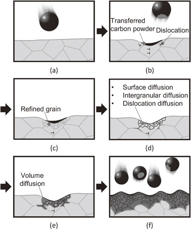
Although the time required for carbon diffusion via AIH-FPP carburization was similar to that required for conventional carburizing, the mechanisms differed significantly. Therefore, we discuss the mechanism of carbon diffusion during AIH-FPP. As previously mentioned, carbon transformed into a gas phase and diffused into materials during conventional carburization processes. However, during AIH-FPP carburization, oxygen and hydrogen were absent in the chamber. Therefore, chemical reactions related to carbon monoxide, ethylene, and acetylene, which occurred during conventional carburization, did not occur; however, the carbon powder transferred from the carbon/steel MC particles directly diffused without any chemical reactions. The mechanism of carbon diffusion via AIH-FPP is illustrated in Fig. 14.
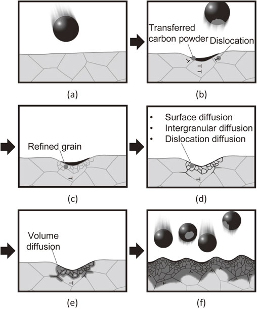
This figure schematically shows the microstructure at the cross-sectional surface of the induction-heated specimen shot with carbon/steel MC particles. When the carbon/steel MC particles were shot to the specimen (Fig. 14(a)), carbon powder was transferred to the treated surface, and dislocations were introduced beneath the surface (Fig. 14(b)). The grains near the surface were refined owing to dynamic recrystallization (Fig. 14(c)). The increased grain boundaries and dislocations became diffusion paths for carbon, and the transferred carbon powders diffused to the grain boundaries near the surface (Fig. 14(d)) and subsequently inside the grains (Fig. 14(e)). This cycle was repeated by continuous particle peening; consequently, a carbon diffusion layer formed on the treated surface (Fig. 14(f)). This carbon diffusion mechanism differs from that of conventional carburizing processes, and explains the experimental results of this study without any contradiction.
In addition, the eddy currents carried through the surface of metals during induction-heating may accelerate carbon diffusion. Eddy currents that pass through conductors by electromagnetic induction when the magnetic flux density is varied are concentrated at the specimen surfaces owing to the skin effect. The authors demonstrated that during gas blow induction-heating nitriding, which is a nitriding process using induction-heating with blowing nitrogen gas, nitrogen diffusion was accelerated in the region where the eddy current density was high.18) During AIH-FPP using carbon/steel MC particles, eddy currents may accelerate carbon diffusion.
5. Conclusions
AIH-FPP was performed on industrial pure iron at various temperatures using carbon/steel MC particles, which were mechanically milled into carbon powders and fine steel particles. Detailed analyses of the treated surfaces were performed to evaluate and discuss the effects of the surface modification and its mechanisms. The main conclusions of this study are listed below.
-
(1)
Analysis of the cross-section of the specimen by EPMA, microstructure observations and measurements of Vickers hardness revealed the formation of a carbon diffusion layer near the treated surface via AIH-FPP using carbon/steel MC particles.
-
(2)
The effects of treatment conditions on the formation of the modified layer were evaluated based on the design of experiment. The results demonstrated that among the treatment temperature, peening time, and gas flow rate, the treatment temperature had the strongest influence on the thickness of the carbon diffusion layer.
-
(3)
Based on the results of the design of experiment, AIH-FPP was performed at five temperatures (1073–1473 K). The depth of carbon diffusion depended on the treatment temperature; namely, the depth of carbon diffusion increased with the treatment temperature. AIH-FPP treatment above 1273 K caused pearlite formation near the surface and increased the hardness.
-
(4)
During the carburization by AIH-FPP using carbon/steel MC particles developed in this study, the mechanism of carbon diffusion differed from that of practical carburizing; namely, carbon powder was transferred to the surface treated by peening, and the transferred carbon acted as a carbon source and diffused into the specimen. The aforementioned mechanism can be used to explain the experimental results without any contradiction.
REFERENCES
- 1) N. Egami: J. Jpn. Soc. Precis. Eng. 72 (2006) 1071–1074. doi:10.2493/jjspe.72.1071
- 2) D. Yonekura, J. Noda, J. Komotori, M. Shimizu and H. Shimizu: Trans. Jpn. Soc. Mech. Eng. Series A 67 (2001) 1155–1161. doi:10.1299/kikaia.67.1155
- 3) Y. Misaka and K. Kawasaki: J. Jpn. Soc. Heat Treatment 61 (2021) 27–32.
- 4) K. Kawasaki, Y. Misaka and F. Ikuta: Proc. 20th Congress of Int. Federation for Heat Treatment and Surface Engineering, (2012) pp. 64–69.
- 5) A. Sasago, S. Kikuchi, Y. Kameyama, J. Komotori, K. Fukazawa, Y. Misaka and K. Kawasaki: J. Japan Inst. Metals 72 (2008) 347–352. doi:10.2320/jinstmet.72.347
- 6) S. Kikuchi, A. Sasago and J. Komotori: J. Mater. Process. Technol. 209 (2009) 6156–6160. doi:10.1016/j.jmatprotec.2009.04.024
- 7) T. Ito, S. Kikuchi, Y. Kameyama, J. Komotori, K. Fukazawa, Y. Misaka and K. Kawasaki: J. Japan Inst. Metals 74 (2010) 533–539. doi:10.2320/jinstmet.74.533
- 8) T. Ito, S. Kikuchi, Y. Hirota, A. Sasago and J. Komtori: Int. J. Mod. Phys. B 24 (2010) 3047–3052. doi:10.1142/S0217979210066069
- 9) S. Kikuchi, S. Iwamae, H. Akebono, J. Komotori and K. Kadota: Surf. Coat. Technol. 334 (2018) 189–195. doi:10.1016/j.surfcoat.2017.08.001
- 10) S. Kikuchi, S. Iwamae, H. Akebono, J. Komotori and Y. Misaka: Surf. Coat. Technol. 354 (2018) 76–82. doi:10.1016/j.surfcoat.2018.09.021
- 11) S. Takesue, S. Saito, J. Komotori, Y. Misaka and K. Kawasaki: Mater. Trans. 59 (2018) 1452–1457. doi:10.2320/matertrans.H-M2018832
- 12) S. Takesue, Y. Misaka and J. Komotori: ISIJ Int. 61 (2021) 1946–1954. doi:10.2355/isijinternational.ISIJINT-2020-753
- 13) T. Harada, S. Kikuchi, J. Komotori, K. Fukazawa, Y. Misaka and K. Kawasaki: J. Jpn. Soc. Mater. Sci., Jpn. 60 (2011) 1091–1096. doi:10.2472/jsms.60.1091
- 14) S. Kikuchi, I. Tanaka, S. Takesue, J. Komotori and K. Matsumoto: Surf. Coat. Technol. 344 (2018) 410–417. doi:10.1016/j.surfcoat.2018.03.030
- 15) S. Takesue, S. Kikuchi, H. Akebono, J. Komotori, K. Fukazawa and Y. Misaka: Mater. Trans. 58 (2017) 1155–1160. doi:10.2320/matertrans.M2017111
- 16) S. Takesue, S. Kikuchi, H. Akebono, Y. Misaka and J. Komotori: Surf. Coat. Technol. 359 (2019) 476–484. doi:10.1016/j.surfcoat.2018.11.088
- 17) S. Takesue, S. Kikuchi, H. Akebono, T. Morita and J. Komotori: Results Mater. 5 (2020) 100071. doi:10.1016/j.rinma.2020.100071
- 18) S. Takesue, S. Kikuchi, Y. Misaka, T. Morita and J. Komotori: Surf. Coat. Technol. 399 (2020) 126160. doi:10.1016/j.surfcoat.2020.126160
- 19) S. Takesue, S. Kikuchi, Y. Misaka, T. Morita and J. Komotori: Mater. Trans. 62 (2021) 1502–1509. doi:10.2320/matertrans.Z-M2021845
- 20) S. Takesue, K. Watanabe, Y. Misaka and J. Komotori: J. Jpn. Soc. Abras. Technol. 64 (2020) 421–427. doi:10.11420/jsat.64.421
- 21) F.E. Harris: Metal Progress 44 (1943) 265–272.