Abstract
The installation of renewable energy is accelerating to achieve carbon neutrality by 2050. This paper proposes a control system for integrating charge/discharge of stationary and onboard energy storage systems on DC electrified railways. A simulation of the performance of a train operation power shows the effect of the demand response and effective use of renewable energy by adopting the control system for energy conservation.
1. Introduction
The Government of Japan has announced a policy to achieve carbon neutrality by FY2050 and has set an ambitious goal of reducing greenhouse gas emissions by 46% by FY2030 compared with FY2013.
Since carbon dioxide (CO2) emitted from energy sources accounts for most greenhouse gas emissions in Japan, it is very important to reduce these emissions.
The Ministry of Land, Infrastructure, Transport and Tourism (MLIT) of Japan is promoting the following three objectives for the railway sector:
● “Decarbonization of railways” to reduce CO2 emissions through energy conservation and electrification of diesel railcars,
● “Decarbonization by railways” to generate, transport and store renewable energy or hydrogen energy by utilizing railway assets, and
● “Decarbonization supported by railways” to reduce CO2 emissions by promoting citizens to use railway services.
The growing installation of PV (photovoltaic power generation) is contributing to the realization of carbon neutrality in 2050. The power generation characteristics of PVs significantly depends on daylight, season and weather, means that this source of energy differs from other conventional power sources. At the same time, the daily power demand curve of railways is significantly different from the power generation characteristics of PV power. This therefore increases the significance of utilizing stationary energy storage systems (SESSs) for compensating differences in power generation and consumption. However, conventionally SESS is installed to utilize regenerative energy of electric trains. Therefore, it is necessary to improve methods for controlling conventional SESS to utilize PV energy which is generated on the power grid side.
To contribute to “decarbonization of railways” and “decarbonization by railways,” firstly, the authors have proposed a new charge/discharge control method for SESSs to charge PV energy from the power grid. Secondly, the authors have proposed an integrated control method for some SESSs and onboard energy storage systems (OESSs) in the DC traction power supply system. In addition, the authors have carried out a study on effectiveness of the demand response (DR) control system for the integrated ESSs.
2. Charge/discharge control method of ESSs for utilization of both regenerative energy and renewable energy
2.1 Outline of ESSs for electrified railway systems
SESSs installed in Japan today are for effective use of regenerative power in DC electrified railways or used as emergency power sources in case of a disaster such as a large earthquake. In addition, OESSs are mainly used as a traction power sources on non-electrified lines and an emergency power sources for lighting or allowing trains to run to nearby stations on electrified lines. The typical kWh-capacity of SESS is less than 500 kWh, and that of OESS is less than 30 kWh per car when running on electrified lines, respectively.
2.2 Concept of proposed charge/discharge control
Figure 1 shows an image of applying SESSs to the DC Traction Power Substation (TPSS) [1] to contribute “decarbonization of railways.” PV is selected as an example of renewable energy in this study.

Fig. 1 Application of PVs and SESSs for DC TPSS
The power load for traction substations tends to be larger during rush hours, such as in the morning and in the early evening. On the other hand, the power generated by renewable energy sources such as PV is usually high during the day. Therefore, the load of the TPSS and the generated power of PV are quite different in terms of their characteristics. The excess PV energy can be absorbed and can be discharged to electric trains by using SESSs. In addition to the use of PV energy, the use of utilizing regenerative energy through the braking of electric trains is also promising.
In order to realize the power flow shown in Fig.1, it is necessary to add new charge/discharge control functions to the conventional SESS. Therefore, the authors propose two types of control function. The proposed functions of the SESS are shown in Fig. 2.

Fig. 2 Proposed charge/discharge control characteristics of SESS for charging PV energy from power grid
The first of the two functions is to control PV energy charge in the standby mode of the conventional SESS. The SESS is charged when the catenary voltage is higher than the charge starting voltage “Vc.” On the other hand, the SESS is discharged when the voltage is lower than the discharge starting voltage “Vd.” Furthermore, when the voltage is between “Vc” and “Vd,” the SESS is charged by the target current “Iabs.” Note that “Iabs” is calculated from the surplus PV energy and the nominal voltage of catenary.
The second function is to adjust state of charge (SOC) for SESS. It is important to control the SOC correctly to get a lot of charge from grid when excess PV power is being produced. The authors propose the changeable discharge starting voltage control depending on the SOC [1]. The target SOCs of SESS are set as SOC(T)* depending on time. “Vd” is increased to get more opportunities of discharge when the current SOC(t) is higher than the target SOC(T)*. The discharge energy is then increased through the control. On the other hand, “Vd” is decreased to cut the chances of discharge when the current SOC(t) is lower than the target SOC(T)*.
2.3 Simulation result of charge/discharge control
The authors studied the proposed control method by using a simulation model [2, 3]. The simulation model of a DC electrified railway line is shown in Fig. 3. All the trains stop at every station on the railway line. Each of the train sets consists of 6 cars. The diagram used in this railway line is the same as that of an actual commuter line. The train operating time treated in this simulation is 24 hours (from 1:00 to 25:00). The nominal voltage of catenary is DC 1,500 V. The line is 38.5 km long with double track and 19 stations. Each TPSS has a 3 MW rated rectifier. Each TPSS receives AC power supply from power grid, and supplies to DC traction power supply system and 6.6 kV 3-phase AC auxiliary trackside loads system. There are two large-scale stations, two medium-scale stations and 15 small-scale stations. The maximum values of load power of the three capacity types are 1,000 kW, 200 kW and 20 kW, respectively. A PV and a SESS are connected to the TPSS 01. The values of rated power of the PV and SESS are 2,000 kW and 3,000 kW respectively. To absorb large generation energy of the PV, the rated energy of the SESS is set for 6,000 kWh, which is much large compared to conventional SESSs. Figure 4 shows an example of the power characteristics for the PV output and the sum of station load. Surplus energy (4.8 MWh) is produced in the daytime since the PV output exceeds the sum of station load. The part of the surplus energy (1.8 MWh) is consumed for the DC traction power supply system. The rest of the surplus energy (3.0 MWh) is required to be suppressed. Such surplus energy can be therefore utilized by applying a SESS to the TPSS 01.

Fig. 3 Simulation model of DC electrified railway with SESSs and PV

Fig. 4 Surplus energy at TPSS01
The calculation results of the utilized surplus PV energy and regenerative energy under the following conditions are shown in Fig. 5.

Fig. 5 Effect of utilizing regenerative or surplus PV energy
● No SESS in TPSS 01
● Conventional charge/discharge control of the SESS
● Proposed charge/discharge control of the SESS
A comparison of the regenerative energy utilized in the case of conventional charge/discharge control with that of the proposed charge/discharge control is nearly equal. Therefore, the proposed control method does not lead to degraded energy saving. On the other hand, the utilized surplus PV energy by applying the proposed control method is 13% larger than when applying the conventional control method.
The charge/discharge characteristics of the SESSs and the characteristics of the SOC are shown in Fig. 6. It shows that the charge by surplus PV energy contributes to gradual rise of the SOC from 08:00. The target SOC is set 0% after 16:30, therefore the SESS is discharged, and the result of the SOC decreases gradually. The regenerative energy is charged, and the powering energy is discharged by the SESS during the train operation period. The SESS is however constantly charged in the daytime depending on the ordered target current.

Fig. 6 SOC and current characteristics
3. Integrated control of SESSs and OESSs
3.1 Concept of integrated control
In the previous chapter, each SESS operates individually in accordance with the control shown in Fig. 2. In order to effectively increase charge of surplus PV energy from power grid, it is necessary to comprehensively control all of SESSs. The authors propose an integrated control method of SESSs for DR in accordance with the requirement of a grid manager [4] to contribute to “decarbonization by railways.” The concept of the integrated control is shown in Fig. 7. There are two types of DR. One is to increase consumption in DC traction power supply system, which the authors call as “up DR.” The other is to reduce consumption in DC traction power supply system, which the authors call as “down DR” in this paper.

Fig. 7 Concept of integrated control for DR
The authors propose a concept of “SESSs manager” to realize the proposed control in this paper. The SESSs manager distributes to the charge current Ib to each SESS. “P*upDR” is the target power of the charge which is sent by the grid manager to the SESSs manager. On the other hand, “P*downDR” is the target power for reduction which is also sent by the grid manager to the SESSs manager. Note that the polarity of each Ib is set to minus when P*downDR is set. The target current Ib and the target SOC are the only control information between the SESSs manager and the SESSs. Ib corresponds to Iabs shown in Fig.2.
3.2 Expansion to SESSs and OESSs
In this study, the authors propose an “integrated control” system in which an external charging/discharging control is applied to the OESSs [5]. Although the installation locations and capacities of SESSs are known, OESSs move along the railway line and the number of electric trains equipped with OESSs is not constant due to traffic demand, vehicle inspection and other factors. It is therefore necessary to determine the number of available OESSs and to manage their chargeable/dischargeable capacities. Two controllers, the “SESS manager” and the “OESS manager,” are used in this study to realize above-mentioned functions. The SESS manager regards the OESS manager to be one virtual SESS and includes the OESS manager in its control.
Figure 8 proposes the concept to add the “OESS manager.” The procedure of this control is as follows:
1) The power grid manager sends DR event information such as start time, duration, and target charging/discharging power Pinput to the SESS manager.
2) The SESS manager and the OESS manager collect the chargeable/dischargeable capacities of their own control targets.
3) The SESS manager distributes the charging/discharging current to the control targets according to (1).
|
I
dist
i
=
P
input
1500
×
C
available
i
∑
C
available
i
| (1) |
where, Iidist and Ciavailable refer to the distributed charging/discharging current and chargeable/dischargeable capacity of the i-th object of management. The target current is converted by dividing the target power by the nominal voltage of 1,500 V.

Fig. 8 Concept of integrated control for SESSs and OESSs
Figure 9 shows a schematic diagram of the DC electrified railway line targeted in this study. The nominal OCS voltage is DC 1,500 V. The main line is about 57.7 km long, with double track from station 1 to station 24 and single track from station 24 to station 32. The branch line is about 9.8 km long and is double track. The total number of electric trains is 43, with 39 trains running on the main line and equipped with OESSs. Each of these 39 trains consists of seven cars. The other four trains run on the branch line and do not have OESSs. Each of these trains consists of six cars. Figure 10 shows the location of the traction power supply installation. There are 11 substations and SESSs are installed in three substations as shown in Fig. 10. Tables 1 and 2 show the specifications of the rectifier in the DC substations and those of SESSs and OESSs, respectively.

Fig. 9 Simulation model of main line for integrated control
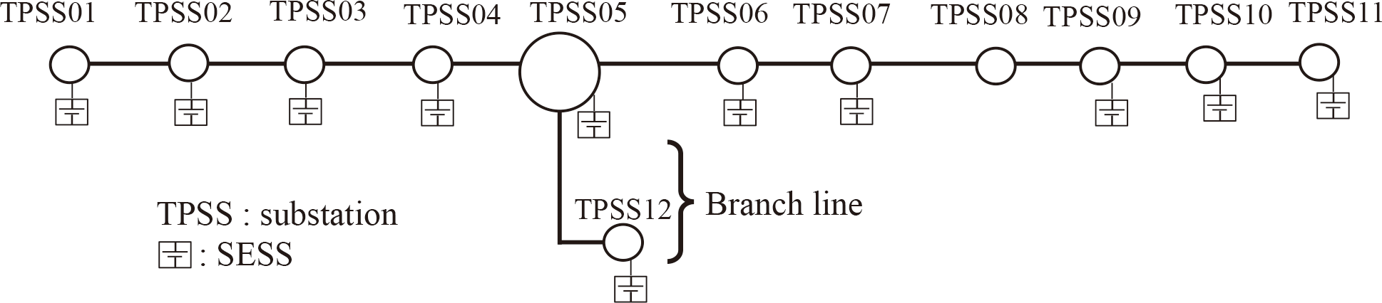
Fig. 10 Simulation model of DC traction power supply system for integrated control
Table 1 Specification of DC TPSS
| Specifications |
Value |
| Nominal voltage [V] |
1,500 |
| Rated power [kW] |
6,000 |
| Voltage regulation ratio [%] |
8 |
| No load voltage [V] |
1,620 |
Table 2 Specification of SESSs and OESSs
| Items |
Specifications |
| SESSs |
OESSs |
| Usage |
Efficiency use of regenerative power |
Power source in emergency condition |
| Number |
11 |
39 |
| Capacity |
500 kWh per a SESS |
110 kWh per an OESS |
| Available SOC zone |
20% to 80% |
10% to 90% |
| Available capacity |
300 kWh per a SESS |
88 kWh per an OESS |
| Initial SOC |
50% |
90% |
| Efficiency of charge/discharge |
90%/90% |
90%/90% |
The period covered by the simulation is 4 hours, from 10:00 to 14:00. In a DR scenario, the authors assumed a condition where the grid manager commands an additional 1,000 kW of demand power from 11:00 to 13:00, in response to excess renewable energy flowing into the power grid. Table 3 shows the details of the DR command. Starting 30 minutes prior to the DR duration, a pre-discharge was carried out at a constant current to increase the chargeable capacities of the SESSs and the OESSs. Then, during the DR duration, the reference power value Pinput was set to 1,000 kW. For one hour after the DR duration, charging and discharging at a constant current was carried out to restore the respective SOC of the SESSs and the OESSs to their initial values.
Table 3 Assumed DR command
| Duration |
Details |
| SESSs |
OESSs |
| 10:30 to 11:00 |
Each SESS discharges 50A until its SOC reaches 30% |
Each OESS discharges 50A until its SOC reaches 0% |
| 11:00 to 13:00 |
P
input = 1,000 kW |
| 13:00 to 14:00 |
Each SESS discharges 50A until its SOC reaches 50% |
Each OESS charges 50A until its SOC reaches 100% |
The simulation method used is an in-house developed “Train operation power simulator” [6]. The simulation time step is set to 1 second.
Figure 11 shows the total charging/discharging power versus time of the SESSs and the OESSs when a DR command is received. In this figure, the baseline of the total power is increased by 1,000 kW in the DR duration. Figure 12 shows the SOC versus time of each controlled object collected by the SESS manager and the OESS manager.

Fig. 11 Charge/discharge power characteristics for integrated control

Fig. 12 SOC characteristics for integrated control
The charge/discharge power fluctuates in a positive direction in Fig. 11, indicating that regenerative power has been charged in all time periods. The total charge/discharge power of all the SESSs and the OESSs exceeds the DR limit of 1,000 kW for most of the two hours. However, SOCs of some OESSs reached the upper limit from 12:00 and the charging capacity of the OESSs gradually decreased. The charge power was finally less than the DR power before 13:00. There is room to improve the DR response by equalizing the variation in the SOC of the SESSs.
Figure 12 shows that the SOC of the SESSs and the OESSs during the DR period changes in accordance with the contents of Table 3. It was confirmed that the SESSs and the OESSs have been charged or discharged in accordance with the demands of the integrated controller.
4. Conclusions
In this study, the authors proposed new SESS control methods for the DC traction power supply system. In addition to these methods, the authors proposed an integrated control method for stationary energy storage systems (SESSs) and onboard energy storage systems (OESSs) on DC electrified railways. The simulation results confirmed that SESSs and OESSs performed charging and discharging approximately as planned by the DR command by using this control method.
Acknowledgment
This work was financially supported in part by the Japanese Ministry of Land, Infrastructure, Transport and Tourism.
References
- [1] Oide, T. and Konishi, T., “Controlling Power Demand of Railways to Follow Output Characteristics of PVs Utilizing Large Scale Energy Storage Connected to DC Traction Power Supply System,” IEE-Japan Industry Applications Society Conference, No. 5-1, pp. 103-106, August 2022 (in Japanese).
- [2] Morimoto, H. and Yoshii, T., “Extension of DC traction power supply simulation tool,” J-RAIL2015, SS 3-4-2506, December 2015 (in Japanese).
- [3] Shimizu, K., Ogata, T. and Morimoto, H., “Technical issues related to reproduction of EN 50641 requirements on DC electric traction power supply system simulation,” IEE-Japan, TER-23-037, MSS-23-003, pp. 13-19, March 2023 (in Japanese).
- [4] Konishi, T. and Ogata, T., “Improvement of utilizing Renewable Energy by applying Demand Response Control for Energy Storage System in DC Electrified Railway,” J-RAIL2022, S7-4-2, December 2022 (in Japanese).
- [5] Ogata, T., Saito, T. and Konishi, T., “An Integrated Control Method of Stationary and Onboard Energy Storage Systems in DC Electric Railway,” The Annual Meeting record IEE Japan, No. 5-213, pp. 367-368, March 2023 (in Japanese).
- [6] Ogawa, T., Takeuchi, Y, Morimoto, H., Kageyama, M. and Minobe, S., “Estimation Method of Energy Consumption by Using Train Operation Power Simulator,” IEE Japan Transaction on Industry Applications, Vol. 141, No. 5, pp. 374-387, May 2021 (in Japanese).
Authors

|
Takeshi KONISHI, Dr.Eng.
Chief Researcher, Power Supply Systems Laboratory, Power Supply Technology Division
Research Areas: Power Supply |

|
Takamitsu OGATA
Researcher, Power Supply Systems Laboratory, Power Supply Technology Division (Former)
Research Areas: Power Supply |

|
Tamanosuke OIDE
Researcher, Power Supply Systems Laboratory, Power Supply Technology Division (Former)
Research Areas: Power Supply |

|
Tatsuhito SAITO, Dr.Eng.
Assistant Senior Researcher, Hydrogen and Sustainable Energy Laboratory, Vehicle Technology Division
Research Areas: Onboard Energy Storage System, Fuel Cell Train |