Review
Macrosegregation in Steel Ingots: The Applicability of Modelling and Characterisation Techniques
2013 Volume 53 Issue 6 Pages 935-949
Details
2013 Volume 53 Issue 6 Pages 935-949
The macro-scale segregation of alloying elements during the casting continues to afflict the manufacturers of steel ingots, despite many decades of research into its prediction and elimination. Defects such as A-segregates are still commonplace, and components are regularly scrapped due to their presence, leading to increased economic and environmental costs. With the growth of the nuclear power industry, and the increased demands placed on new pressure vessels, it is now more important than ever that today’s steel ingots are as chemically homogeneous as possible.
This article briefly reviews the development of our current understanding of macrosegregation phenomena during the 20th century, before going on to assess the latest developments in the field of macrosegregation modelling. The aim of the text is to highlight the shortcomings of applying contemporary macromodels to steel-ingot casting, and to suggest practical alternatives. In addition, the experimental characterisation of macrosegregation is explored, and a review of the various techniques currently available is presented.
On the solidification of alloys, solute is partitioned between the solid and liquid to either enrich or deplete interdendritic regions. This naturally leads to variations in composition on the scale of micrometres, i.e., to microsegregation. Macrosegregation, however, refers to chemical variations over length scales approaching the dimensions of the casting, which for large ingots may be of the order of centimetres or metres. Microsegregation can be removed by homogenisation heat treatments, but it is practically impossible to remove macrosegregation due to the distances over which species are required to move. Almost all macrosegregation is undesirable for casting manufacturers as the chemical variations can lead to changeable microstructural and mechanical properties. Thus there has been, and still remains, a great interest in predicting and eliminating macrosegregation in cast products.
It is true that the vast majority of the world’s steel is now continuously cast, but ingot casting is still required for the production of heavy industrial components which comprise large high-cost single-piece sections, such as the pressure vessels required for nuclear power generation. The effects of macrosegregation are critically important in such applications, and the ability to predict segregation severity and location is highly sought after. This article reviews the development of predictive methods for macrosegregation, assesses the viability of their use today in an industrial environment, and goes on to highlight the key factors limiting their effectiveness. The techniques which may be used to measure macro-scale segregation and structure in ingots will also be briefly discussed.
The first examinations of macrosegregation phenomena in steel ingots were carried out many decades ago and although our understanding of the processes leading to segregation has improved considerably, the same patterns can still be observed in ingots made today.1,2) These, shown in Fig. 1, include A-segregation, V-segregation and negative base segregation.

Schematic of the different types of macrosegregation that can be found in large ingots. Positive segregation is denoted by + symbols (regions enriched in solute) and negative by – (regions depleted). Similar figures can be found in other macrosegregation reports.8)
Up to the mid-1960s, solute buildup at the tips of advancing solid interface was believed to be the predominant underlying cause of macrosegregation phenomena in ingots by a number of authors.1,3,4,5,6) However, this premise has since been demonstrated to be erroneous by numerous theoretical and experimental investigations. It is now well recognised that the majority of solute is rejected sideways from a growing dendrite, enriching the mushy zone, and that build up in front of dendrite tips is negligible in this regard (the boundary layer has a thickness of the order of Dl/v, which for ingot solidification may only be ~ 10–5 m).7)
All types of macrosegregation are derived from the same basic mechanism: that of mass transfer during solidification. The movement of enriched liquid and depleted solid, Fig. 2, can occur through a number of processes:

Schematic of the processes which lead to mass transport during ingot solidification. (a) Convective flows in the interdendritic liquid (+ symbols denote enrichment in solute, whilst – denote depletion), (b) grain sedimentation (more generally solid movement), (c) liquid flow to feed solidification shrinkage and (d) mushy-zone deformation. Note that the columnar solid in (a), (c) and (d) has grown from the mould wall.
• Convective flows due to density gradients caused by temperature and composition variations in the liquid, Fig. 2(a). The thermal and solutal buoyancy contributions can either aid or oppose each other depending on whether local temperature and concentration fields cause liquid density to increase or decrease. The convection due to the coupled action of temperature and solute is known as thermosolutal convection.
• Movement of equiaxed grains or solid fragments which have either nucleated heterogeneously in the melt, become detached from dendrites due to remelting/stress, or have separated from the mould wall after pouring, Fig. 2(b). Equiaxed grains in steels are denser than the surrounding liquid and will hence tend to sink. This mechanism, along with convective fluid flow, is a dominant macrosegregation process in large ingots.
• Flow to account for solidification shrinkage and thermal contraction of the liquid and solid on cooling, Fig. 2(c).
• Deformation of the solid network due to thermal stresses, shrinkage stresses and metallostatic head (i.e., the pressure provided by the liquid metal above), Fig. 2(d).
• Imposed flows due to pouring, applied magnetic fields, stirring, rotation etc.
The complex interplay between these mechanisms makes accurate modelling of macrosegregation phenomena a formidable challenge, often involving complicated mathematical treatments. Thus, before such models are discussed, some qualitative explanations of how these mechanisms lead to macrosegregation defects are given below.
2.1. A-SegregationA-segregates arise due to the flow of solute-rich interdendritic fluid via thermosolutal convection. They are characterised in the final solidified microstructure as channels of enriched solid, often with near-eutectic composition. Their formation mechanism can be described as follows: in steels the enriched interdendritic liquid will often be less dense than the bulk liquid, and will hence tend to rise. As the liquid moves towards the bulk liquid and the top of the ingot it will increase in temperature, but its composition will remain nearly constant due to slow mass diffusion. This hotter enriched liquid then causes delayed growth or remelting of the solid around it, creating persistent solute-enriched channels. A-segregates are also commonly referred to as ‘channel segregates’ or ‘freckles’ when they arise in directionally-solidified castings (when the melt is cooled from below, for instance during the casting of single crystal nickel-based superalloy turbine blades).
The prevalence of A-segregation has meant it is perhaps the most investigated of all macrosegregation phenomena, not only in steels, but also many other systems. Some of the earliest studies which identified the importance of mushy-zone fluid flow on macrosegregation were made by the Japanese steel industry in the 1950s, and focused on A-segregates. Kawai9) was one of the first to attribute their formation in ingots to the gravity-induced flow of enriched mushy-zone liquid, whilst others confirmed that liquid density changes due to composition were of critical importance (by reducing the Si content and increasing Mo levels, it was found that A-segregation could be minimised).10,11) Later on, Suzuki et al. found that A-segregates started to form in the mushy zone when the fraction solid was between 0.3 and 0.35, and persisted until the fraction solid was as high as 0.7.12)
Similar results were found by investigations of the NH4Cl–H2O system, a favourite of researchers because its transparent liquid allows the mushy zone to be directly observed during solidification. Particularly noteworthy NH4Cl–H2O studies were carried out by McDonald and Hunt and Copley et al., and demonstrated that increased solidification times (and alloy freezing ranges) increased the severity of channel segregation.13,14,15,16,17,18) The Pb–Sn system was also the subject of a considerable research effort.19,20,21,22,23) Streat and Weinberg not only examined compositional and liquid-density effects in Pb–Sn, but also the extent of fluid drag within the mushy-zone network (i.e., the permeability, discussed below) on channel formation. The nucleation and stability of channel segregates were like- wise investigated experimentally and theoretically in a number of studies.24,25,26)
A-segregation is of particular concern to the manufacturers of pressure vessels required for nuclear power generation. Such vessels are created by removing the core of the ingot after casting to create a shell, which is then forged and machined to finish. Welds may then be made to attach nozzles or end sections, and there is a concern that A-segregates could impinge on these welds. The enriched material within A-segregates is commonly associated with increased hardness and decreased toughness relative to bulk, which could lead to reduced weld integrity.27) Figure 3(a) shows the A-segregation present in material taken from a low-alloy steel ingot (0.2C–1.3Mn–0.7Ni–0.5Mo) after forging. Figures 3(b) and 3(c) show the difference in microstructure following slow cooling from austenisation at 940°C at 0.1°C s–1; the hardness of the positively-segregated material was ~ 80HV2 higher than the bulk material in this untempered state.28)

(a) Low-alloy steel plate taken from forged ingot, macroetched in 5% nitric acid. A-segregates (in cross-section) are seen as ellipses of dark material; the remnants of primary dendrite arms also appear as lightly-etched bands. The plate normal is aligned with the vertical axis of the ingot. (b) and (c) show the effect on microstructure of slow cooling from austenisation at 940°C at 0.1°C s–1. The bulk material in (b) shows a Widmannstätten ferrite structure, whilst the enriched material in (c) is a mixture of bainite, retained austenite, and martensite. Both were etched in 2% nital and imaged with an optical microscope.28)
It has been proposed that negative base segregation can arise in ingots due to two processes: (i) the settling of solute-depleted (negatively-segregated) equiaxed grains at the bottom of the ingot under the action of gravity and (ii) the general rise of solute-enriched liquid upwards. There has been some dispute over which of these mechanisms is predominant: early investigations by Marburg and others suggested that the flow of enriched liquid upwards was the dominant factor, citing the appearance of negative segregation in ingots which apparently contained no equiaxed zone.3,5) But in reality it is rarely the case that steel ingots undergo fully columnar solidification, and more recent modelling investigations have tended to lend greater significance to grain sedimentation.29)
It has been found that the equiaxed zone in a low-alloy steel ingot may extend to well over half its height,29,30) and that the equiaxed grains at the very base of the ingot are more globular in form than those found further up the ingot (globular grains are rounder and not so branched, equiaxed grains typically start growing in this form before becoming dendritic).29,31,32) Disconnected grains can form through a number of mechanisms, which include heterogeneous nucleation in the melt and dendrite-arm detachment. The predominant mechanism is usually detachment due to the action of convective flows or shrinkage stresses. Note that if the density of enriched liquid is higher than the bulk, as is possible, then flow in the mushy zone will be generally downwards, and this may reduce the severity of both negative base segregation and any positive segregation (enrichment) at the ingot top.
2.3. V-SegregationDuring the final stages of ingot solidification the centre of the casting is usually occupied by a network of loosely-connected equiaxed grains. It is thought that V-segregates arise due to the fissuring of such networks under action of metallostatic head (i.e., the weight of material above) and solidification shrinkage, see Fig. 4, which leads to the formation of open shear planes that can fill with any remaining liquid.8,33,34) This remaining liquid will have been enriched throughout solidification by convective flows from the mushy zone, and also by solidification in the final cavity, and it solidifies to produce positively-segregated solid. Indeed, the solidification of enriched material at the end of solidification generally produces the often-referred-to centreline segregation.

Schematic showing formation of V-segregates through shearing on preferred planes during settling and compression of equiaxed grains. Adapted from Flemings.8)
Despite being regularly observed, V-segregation is generally not well understood other than through the mechanism given above. Theoretical treatments and models of V-segregate formation in ingots have yet to be produced and are likely to prove challenging as they would need to account for phenomena including equiaxed grain sedimentation, mushy zone deformation and fluid flow. Nevertheless, the total lack of literature on V-segregation in ingots is perhaps indicative of a further issue - the disinterest of manufacturers in the subject. It is often the case that the centres of ingots are removed after casting (as highlighted above) or that the effects of V-segregation are insignificant for end applications. Not only would modelling of V-segregation be a great challenge, but it may not prove to be particularly useful.
2.4. Other SegregationHot-top segregation, banding and inverse segregation are other examples of defects that can arise during ingot casting. Their formation and severity, like most of the other macrosegregation defects, is dependent on casting procedures and ingot size, and hence they will not always be observed in large ingots.
Hot-top segregation refers to the positive segregation which arises below the tops of ingots due to the flow of enriched liquid from the head of the ingot during the latter stages of solidification. If the temperature gradient moving away from the top surface of an ingot is conducive to solidification (due to insufficient insulation, for example) then a dendritic front will advance downwards from the head surface. Enriched, cool liquid from this solidification may then flow downwards and enrich the liquid below the top.35,36) During the early stages of solidification this enriched liquid may spread throughout the large melt pool, but during the final stages (when solidification at the top is most likely) the enriched liquid will remain at the centre and top of the ingot.37)
Improvements in hot-top practices, driven primarily by the need to reduce ingot porosity, have led to reduced levels of hot-top segregation in modern-day ingot making. Note that the hot-top segregation described here is distinct from the general positive segregation often observed at the top of steel ingots, which is formed due to the advection of enriched liquid upwards.
Bands of segregation (i.e., banding) have been found to result from abrupt changes in temperature profile across the mushy zone during the early stages of solidification, which may be caused by thermal pulses from convection or changes in heat transfer due to air gap formation (i.e., unsteady heat flow).38) If the ingot does break free from the mould, solute-rich bands can be formed due to the remelting of solid and expansion of the mushy zone. Changes in conditions which lead to acceleration of the liquidus isotherm toward the ingot centre will also give a similar result. Solute-poor bands are formed when the mushy zone size is reduced.36)
Inverse segregation refers to the positive segregation which can arise directly adjacent to the cold mould wall. It forms due to the motion of enriched interdendritic fluid towards the wall to feed solidification shrinkage in the early stages of solidification.35,39) Its effects are not observed later on in the casting process because buoyancy-driven flow dominates mass transport. Inverse segregation is found most prominently in direct-chill (DC) casting of aluminium alloys, but its significance in steel ingot casting is likely to be low and it is hard to find investigations on the subject.
The first pioneering work on macrosegregation modelling was made by Flemings et al. in the late 1960s.36,40) They began by considering the effect of fluid flow resulting from solidification shrinkage only, i.e., the density difference between solid and liquid, and developed the local solute redistribution equation (LSRE) now so familiar to macromodellers:
| (1) |

Work by the same group later expanded the LSRE model to include the effect of fluid flow in the mushy zone due to buoyancy, see Mehrabian et al.47) Differences in liquid density due to both thermal and solutal effects were accounted for (thermosolutal convection), but because a temperature gradient within the mushy zone was still assumed (and concentration related to temperature via the phase-diagram liquidus), the density of the liquid was a function only of local temperature.
In order to calculate flow velocities in the mushy zone it is essential to take into account the resistance to liquid movement provided by the dendritic network. To this end, Mehrabian et al. used Darcy’s law for flow within a porous medium to modify liquid velocities v according to gravity and pressure drops across a volume element of dendritic mush:
| (2) |
By accounting for density-driven flow, and not just shrinkage, Mehrabian et al. demonstrated that buoyancy-driven flows could lead to A-segregate formation. If the simple LSRE Eq. (1) is considered momentarily, by recognising that
| (3) |
By examining this expression, it can be seen that local remelting (i.e., an increase in liquid fraction) occurs if fluid velocities in the direction of isotherm movement are greater than the isotherm velocities (flow instability):
| (4) |
One of the limiting simplifications in the works by Mehrabian, Flemings et al. is that their models required the input of an experimental or assumed temperature gradient in the mushy zone, and did not use energy conservation equations to find the transient values. Furthermore, despite recognising the effects of both solute concentration and temperature on liquid buoyancy, the two parameters were always dependently related (the composition of liquid was determined by the phase diagram at a given temperature) and their profiles fixed by the imposed temperature field. They also neglected fluid flow in the bulk liquid and coupled flows between the bulk and mushy regions. It was not until the development of multi-domain models, and later continuum models, in the 1980s, that the simplifications were gradually removed.
3.2. Multi-Domain ModelsIn multi-domain models conservation equations for mass, solute, momentum and energy are developed for each region (liquid, mushy and solid) and coupled across the moving boundaries between them. For instance, fluid momentum in the bulk liquid is typically described by Navier-Stokes equations for laminar convective flow, whilst in the mushy zone Darcy’s law is used. One of the earliest attempts to predict transient mushy zone temperature fields by coupling energy and momentum equations was accomplished through a multi-domain model developed by Fujii et al.50) They examined the macrosegregation in a low-alloy steel through the use of a modified LSRE for multicomponent alloys which accounted for complete solid diffusion of interstitituals (lever rule behaviour) and Scheil behaviour for substitutionals.
Importantly, the density of the liquid in their model was a function of both local concentration and temperature and the two fields were no longer fixed. Ridder et al. were the first to examine the effect of natural convective flows in the bulk liquid on interdendritic flows in the mushy zone.51) They did so by coupling equations for flow velocity and pressure in each domain across the liquidus interface. For the bulk liquid, energy and momentum equations were used but solutal effects were not considered.52) Despite its originality in dealing with bulk liquid flows, the treatment did not predict mushy zone temperatures, requiring an a priori knowledge. Perhaps the first truly predictive model for energy and momentum transport, which also examined bulk-liquid flows, was given by Szekely and Jassal.53) They used expressions for energy and momentum in the solid, mushy and bulk-liquid zones and coupled the equations using temperatures and velocities at the domain boundaries.
A key problem with the multi-domain approach, however, is that it requires the tracking of the boundaries between solid, mushy zone and bulk liquid. This is often a difficult task, particularly as the boundaries can take on complex morphologies. In using continuum models this difficulty is removed as they comprise a single set of equations which are equally valid over the solid, mushy zone and bulk liquid.
3.3. Continuum ModelsBennon and Incropera recognised the suitability of continuum formulations for the liquid-solid transformation in the late 1980s and produced a model for a binary system by combining constitutive equations through simple mixture theory (for the full set of equations, see Bennon and Incropera54)). As is usual in continuum formulations, the momentum equations used (in two dimensions) were based on the Navier-Stokes equations for fluid flow, but were altered by the addition of the Darcian term which accounts for the resistance of stationary solid in the mushy zone. Assumptions included laminar Newtonian flow in the liquid with constant viscosity, and the Boussinesq approximation, which states that differences in liquid density are small enough to be neglected apart from when they are multiplied by g, the acceleration due to gravity (inertial differences between two fluids are ignored but weight differences are included). Closure of the model required the coupling of the enthalpy (temperature) and solutal fields, which was accomplished by assuming lever-rule equilibrium solidification.55) The continuum formulation meant that the need for a moving numerical grid was eliminated and the only boundary conditions included in the model were those applied to external domain surfaces. As a result, the first direct numerical predictions of A-segregation were presented.
At almost the same time, Beckermann and Viskanta developed a set of continuum equations almost identical to that of Bennon and Incropera but for the form of the momentum equation.56) Their formulation, however, used a volume-averaging approach (this is generally thought to be more rigorous57)) to obtain macroscopic conservation equations from microscopic relations for each phase, which were then combined to produce a single set of equations valid in all regimes. Direct solution of microscopic equations on a small scale is impractical because of the highly complex interfacial geometries in the mushy zone, but when they are averaged over a suitable volume element, the scale of the problem is changed giving manageable macroscopic relations. For details of the volume-averaging procedure and the form of the macroscopic volume-averaged formulations, see Beckermann and Viskanata.57) Further exploration of aspects of the volume-averaging procedure and assumptions were made by Ganesan, Poirier, and Voller et al.49,58)
Following the pioneering works highlighted above, many studies used similar or modified versions of the same continuum equations to examine a number of different solidification phenomena, including channel formation in directionally-solidified alloys,59,60,61,62,63,64) the effect of solidification shrinkage and pore formation,63,64,65,66,67,68,69,70,71,72,73,74) and the effect of transformation-induced strains.75,76,77) Many authors have also examined the particular formulations and assumptions of the original models.78,79,80,81)
3.3.1. Multi-Phase ModelsA shortcoming of early continuum approaches was that they failed to account for the interaction between liquid and solid phases. Important solidification features, such as local solid concentrations, were simply averaged over both phases or unaccounted for. In particular, this meant that the solid transport which is known to form negative base segregation in ingots was not calculable and model results were commonly at odds with experiment.57) The first studies which attempted to ac- count for solid advection used two approaches. The first used a single momentum equation in which the velocity of a volume element of mush was switched at a certain stage of solidification82,83) or through a continuously-varying function.84,85) The other approach, developed by Ni and Beckermann, involved the use of a ‘two-phase’ model in which separate volume-averaged conservation equations were used for the solid and liquid phases and included interfacial transfer terms.86,87,88) The relative movement of solid and liquid (and momentum transfer between them) was accounted for by using an effective solid viscosity, the value of which changed according to the local solid fraction. If the solid formed a continuous structure, the solid viscosity was set to infinity - i.e., the solid was assumed perfectly rigid - or if the solid did not form a continuous structure, solid viscosity was varied between zero and infinity depending on the nature of the solid environment.
The strength of the two-phase approach is that liquid/solid velocity relationships don’t have to be imposed and that phenomena such as the settling of free solid grains can be modelled. Furthermore, it can predict liquid and solid interfacial com- positions and temperatures, and can also incorporate nucleation and grain-growth calculations.57) Wang and Beckermann utilised a two-phase model to examine features of equiaxed dendritic solidification, including the settling of equiaxed grains and the columnar-to-equiaxed transition (CET) commonly observed in steel ingots.89,90,91) A key feature of their approach was the introduction of a grain envelope, Fig. 6, a fictitious surface which acted as an artificial boundary between the interdendritic and extradendritic liquid. Across the envelope interface, microscopic equations describing grain growth and liquid composition could be linked to macroscopic terms.

Representation of a grain by an envelope containing a solid skeleton and interdendritic liquid. Adapted from Combeau et al.31)
Most metals of commercial interest are not idealised binary systems, but are multi- component alloys which can have complex solidification paths. From the mid-1990s, macrosegregation modellers began to adapt their continuum formulations to deal with multicomponent systems of varying complexity. Difficulties arise when moving to three or more system components that are not found with binary alloys - a given liquidus temperature can be reached through more than one alloy composition, and significant variations in partition coefficients and liquidus slopes can occur. Schneider and Beckermann presented the most comprehensive early multicomponent two-phase model and applied it to a low-alloy steel ingot.92) They solved species conservation equations in the liquid and solid for each system component, and coupled the energy and species conservation equations through thermodynamic equilibrium requirements at the solid/liquid interface. The model was not restricted to either lever or Scheil partitioning, but accounted for varying levels of solid-state diffusion. It was later applied to freckle formation in Ni-based superalloys producing one of the earliest studies in three dimensions.93,94,95,96,97,98) Other multicomponent approaches were presented by Vannier et al.32) and Krane and Incropera,99,100) but have not been widely used.
3.3.3. 21st Century DevelopmentsFollowing on from the pioneering two-phase models of Beckermann et al., many studies in the past decade have focused on the generation, growth and movement of equiaxed grains in convecting melts, and in particular the CET. Beckermann highlighted the need for such research in 2000,101) and it is certainly key for the prediction of negative base segregation in ingots. One would suppose that such models would also be an essential starting point for the prediction of V-segregation, and would be useful to those predicting the location of A-segregates (A-segregation is not found in equiaxed zones).
Investigations during the 21st century included the extension of two-phase models29,31,102) for instance to account for the different behaviours of globular and dendritic equiaxed grains, as well as generation of new formulations,103,104) such as the three-phase treatment of Ludwig, Wu et al. (the phases were stationary columnar solid, equiaxed solid and parent melt).105,106,107) Martorano et al. examined the viability of a CET criterion based on the arrest of columnar solidification by the solute field of growing equiaxed grains ahead (so-called ‘soft- blocking’).108) This was compared to the classical mechanical blocking criterion, in which equiaxed grains ahead of a columnar front physically impede its progress.
The group of Wu, Ludwig et al. later drew on the ideas of two previous equiaxed solidification models by using a two-phase method to compute the velocities of so-called “hydrodynamic phases”, whilst solving for mass transport and solute over three phase regions, the so-called “thermodynamic phases”.89,90,109,110,111,112,113) The interdendritic melt and the solid dendrites, confined in a grain envelope, were regarded as one hydrodynamic phase sharing the same velocity, with the other being the extradendritic liquid. The three distinct thermodynamic phase regions were the solid dendrites, the interdendritic melt and the extradendritic melt. This model was subsequently extended to mixed columnar-equiaxed solidification which required five thermodynamic phase regions: solid dendrites in equiaxed grains, the interdendritic melt between equiaxed dendrites, solid dendrites in the columnar zone, the interdendritic melt between columnar dendrites, and the extradendritic melt and three hydrodynamic phases (the same as in their original three-phase treatment).114,115)
Recently, Ludwig et al. have used their original binary three-phase model to compute macrosegregation in a 2.45 tonne steel ingot.105,116) When compared to two-phase model results and experimental measurements, it was found the results of the two and three phase simulations were significantly different, and the simplified columnar-only two-phase scheme more accurately reproduced experimental findings. It was suggested that the three-phase approach could have introduced too many equiaxed grains, or that the experimental ingot had undergone mostly columnar solidification.
Other studies in the past decade or so have examined the optimisation of numerical solution methods and solution schemes117,118,119,120,121,122,123) (following on from Ahmad et al. in 1998)124) as well as the incorporation of mechanical stresses into simulations.125,126) A significant body of work, however, has been completed using highly-simplified binary single-phase simulations.127,128,129,130,131) This is almost certainly because of the complexities and excessive computing times associated with large multiphase simulations, as will be discussed in the following section.
There seems to be a general consensus amongst macromodellers that it would be unwise to rely on even the best macrosegregation models of ingot casting for quantitative results, and that basic trends are often not predicted reliably, particularly in commercial codes.132,133) The reasons for this appear to stem from two sources: the computational requirements of complex macromodels (which in turn impose constraints and compromises on models), and uncertainties associated with input parameters and auxillary models.
4.1. Computational RequirementsIn 1999 Gu and Beckermann134) utlised the multicomponent two-phase model of Schneider and Beckermann92) to predict macrosegregation patterns in a large cuboidal 65 t commercial ingot measuring 1.016 × 2.083 × 2.819 m. It was recognised, however, that in order to predict A-segregates, computing times would have been prohibitively long (years) for the required mesh size, despite the reduced geometry used. In relation to this problem, a year later Beckermann predicted that macromodels which included the generation, growth and settling of equiaxed grains, with sufficiently small mesh sizes to resolve flow patterns associated with A-segregates (i.e., on a scale of a few millimeters) for large ingots would be unavailable for at least the next decade.101) Today, some twelve years on, macromodels which include equiaxed grain motion are restricted to binary systems and small geometries struggle to resolve A-segregates, and are too computationally expensive for use in industry.31,106,116) According to Voller et al., models which solve equations on the nanometre scale and coupled them to macroscopic heat and mass transfer terms will not be computationally feasible until at least 2050.135)
The computational demands of macrosegregation models have often led modellers to reduce the size of the system modelled, to increase mesh sizes or introduce significant simplifications. This is particularly evident in studies introducing new theory or examining model sensitivity to certain parameters. The CET investigations referred to above used only binary systems and small geometries, and the model of Ludwig et al., for instance, was incapable of predicting channel formation.106) Indeed, many recent studies have resorted to the original treatments by Bennon and Incropera and Beckermann et al. to deliver their predictions.128,129,130,131,132)
Reducing the size of the model system can drastically reduce times, and using symmetry is certainly essential, but results can only be scaled up to larger problems with caution (macrosegregation will not normally arise in small ingots, see later). Increasing mesh sizes often means that certain features, such as A-segregates, are not resolved and changes can significantly affect computed segregation patterns, see Fig. 7.31) To resolve channel segregates, mesh sizes need to be smaller than channel widths (usually of the order of a few millimetres) and need to be even less if results are to be mesh independent.59,60,92,95,117,136) Introducing too many simplifications can also gravely impact a model’s predictive power. Commercial software packages are often guilty of making significant simplifications in order to deliver sensible computing times in an industrial setting, and as a result neglect key macrosegregation phenomena, such as equiaxed grain sedimentation.118,119,137,138,139,140) Consequently, their results often appear to provide little predictive insight.
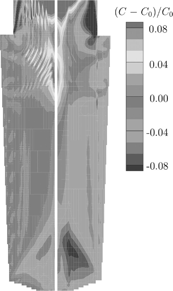
Effect of the grid density on the predicted carbon macrosegregation for an ingot. Model used a fixed solid phase. Left: fine grid. Right: coarse grid. Adapted from Combeau et al.31)
Another issue which continues to plague macrosegregation models is their dependence on the input parameters and auxillary models fed into them, which are them- selves topics of investigation and development. Examples of typical input parameters include density-change coefficients, partition coefficents, liquidus slopes, conductivities, dendrite-arm spacings, heat capacities, latent heats and densities of equiaxed- grain nuclei. Slight variations in such values have been found to influence (often significantly) model results,81,92,105,115,116) and although there are software packages which are able to deliver some of these parameters in steels,141) outputs from them can be limited in their current form (for instance, only values for equilibrium solidification are calculated) and certain parameters, such as those relating to equiaxed grain nucleation, can only be determined experimentally.142) Clearly this is not an ideal situation for those wishing to compare alloys quickly. Similar uncertainty surrounds the auxillary models of microsegregation and permeability which must be supplied to macrosegregation simulations.
4.2.1. Microsegregation ModelsMicrosegregation models are of utmost importance to macrosegregation investigators. It is the microsegregation of elements on the dendritic scale which ultimately leads to enrichment of the liquid and macro-scale advection of species. It is obvious that different results should be expected if one uses an equilibrium lever rule microsegregation model and compares it to a non-equilibrium Scheil treatment,41,42,43) but there is a huge range between these two extreme cases (characterised by incomplete solute diffusion in the solid) which is not so easily modelled. Furthermore, microsegregation in steels often falls in this intermediate area due to the mixture of interestitial and substitutional elements present and the range of solidification times given by various casting processes.
Notable analytical or semi-analytical treatments of this solute redistribution problem have been presented by Brody and Flemings, Clyne and Kurz, Ohnaka and Kobayashi;143,144,145,146) the Clyne-Kurz-Ohnaka models were later modified by Ganesan and Voller and Beckermann.147,148) Their resulting liquid fraction profiles for a 0.5C–3Mn–3Ni (wt%) alloy are compared to the standard lever-rule and Scheil cases in Fig. 8, from which it is clear that microsegregation model selection can significantly influence the predicted solidification behaviour. Despite their attractiveness in terms of calculation speed (neglecting Kobayashi’s treatment149)), these somewhat simplified approaches are not readily applied to steels which can exhibit complications such as the peritectic transition and the effects of multiple alloying additions. Instead, finite-difference approaches have often been used to better predict the onset and effects of the peritectic and other transitions. Ueshima et al.150) predicted the start of the peritectic using empirical relationships based on local solid concentrations, whilst Howe et al.151,152) introduced ‘carbon equivalents’ for alloying elements such that the effect of each partitioned species on the peritectic temperature was accounted for in a pseudo-binary model. More recently the use of thermodynamic databases in steel microsegregation models has become popular153,154,155,156) and kinetic effects have also been incorporated into models.111,157,158,159,160,161,162,163) Nevertheless, adding such complexity into macrosegregation models often comes at great computational expense, and consequently there has been some development of rapid microsegregation models for incorporation into macromodels.164) For those seeking further details on microsegregation models, the review by Kraft and Chang165) is a useful starting point.

Liquid fraction vs temperature plots for a 0.5C–3Mn–3Mo (wt%) alloy found using various microsegregation models. Partition coefficients were obtained from binary phase diagrams. Where needed, the secondary dendrite arm spacing used was 750 μm and the solidification time 5000 seconds (to reflect large ingot solidification). Diffusion information was taken from Fridberg et al.166) Note that the Brody-Flemings treatment is known to give erroneous results for long solidification times.
In order to accurately predict fluid flow through the mushy zone, its permeability, K, must be known. K is a second-order tensor by definition, such that it depends on the direction of fluid flow relative to a porous geometry, but experimenters and macromodellers have usually assumed it to be isotropic or to comprise only two components (in directions parallel and perpendicular to primary dendrite arms). Nevertheless, the development of models for K has represented a formidable challenge for many years, and rightly so. It depends strongly on factors such as local liquid fraction, dendrite arm spacings and dendrite morphologies, and hence not only varies continuously within a mushy zone, but can also vary from alloy to alloy. Estimations of permeability functions have been made by approximating the geometry of the mushy zone and using specialist forms of Darcy’s law, such as the Hagen-Pouseuille model for flow through a bundle of capillary tubes or the Blake-Kozeny (also known as the Carman-Kozeny) model for flow through a packed bed of solids. Many studies have sought to experimentally verify these models,20,21,48,167,168,169) but another common approach has been to find functions by fitting experimental results directly to Darcy’s law.168,170,171,172,173,174)
At high liquid fractions, in excess of 0.7, flow is no longer within an interconnected dendritic network but between dendrite arms. Experimental studies tend to fail in this regime due to the ripening and fragility of dendrites, yet flow here is still of great importance. To avoid these practical constraints, studies by McCarthy, Poirier and coworkers, and others have predicted permeabilities using computer simulations of flow parallel and perpendicular to primary dendrite arms, often through a finite-element Navier-Stokes solver with idealised or experimentally-determined meshes.175,176,177,178,179,180,181,182,183) Many of these studies used the specific surface area (i.e., the surface-area-to-volume ratio) of the dendritic mush in their permeability relations in an effort to capture the effect of dendrite morphology more completely.176,177,179) More fundamentally, some authors have suggested that changes must be made to momentum equations to accurately capture flows at high liquid fractions (that Darcy’s law on its own is not sufficient).61,176)
As regards incorporation into macromodels, researchers have typically taken two approaches, either using a single permeability relation approximate for all liquid fractions (e.g., a Blake-Kozeny function) or switching between functions based on the local fraction liquid (often a Blake-Kozeny relationship is used at low liquid fractions and at high fractions a suitable relationship based on computer simulations).71,72,73,74,92,93,94,97,169) Results of macromodels have demonstrated that the use of different mushy-zone permeability functions, and neglection of permeability anisotropy, can have a significant effect on the macrosegregation predicted, including the number, length and orientation of channel segregates.71,99,127,128,184)
The treatments described above have considered only the permeability of mushy zones during columnar solidification, yet it is clear that a significant proportion of solidification (and segregation) in large steel ingots occurs in the equiaxed regime. Wang et al. examined the permeability of equiaxed structures in the mid 1990s, finding that fluid drag was a function of various terms including arm spacings and grain densities, but recently this complex subject appears to have received little attention.185) It is evident that an improved understanding of grain growth and motion in a convecting melt would only better the predictive power of multi-phase models.101)
4.2.3. Dendrite-Arm SpacingsPermeability relations are typically functions of both primary and secondary dendrite arm spacings (understandably, it is usual to find expressions for flow perpendicular to primary arms to be more dependent on secondary-arm spacings than those for flow parallel), and this can lead to further complications when using them in calculations. In many different ferrous and non-ferrous alloys, both primary- and secondary-arm spacings have been shown to exhibit a striking relationship with cooling rate over several orders of magnitude, see Fig. 9 for secondary-arm spacings in steel. An increase in cooling rate leads to a decrease in both primary- and secondary-arm spacings. Yet despite this clear trend, there are still issues associated with the prediction of arm spacings.

The cooling rate during solidification can be expressed as a product of the temperature gradient, G, and the growth (isotherm) velocity R, and hence on the basis of graphs such as Fig. 9 expressions for arm spacings using a single exponent were developed:
| (5) |
| Source | Expressions (in μm) | Notes |
|---|---|---|
| Suzuki et al.186) |
| Found by fitting data for low- alloy steels given in Fig. 9. Valid for 0.14<CC<0.88. |
| Jacobi et al.187) |
| Found for a 0.59C–1.1Mn (wt%) alloy.* |
| El-Bealy193) |
| Found by fitting data for various low-alloy steels. λ1 expression only valid for 0.15<CC<1.0, λ2 only for CC <0.53.* |
| Won et al.194) |
| Found by fitting data for various low-alloy steels. Only valid for 0.15<CC* |
| Cicutti et al.197) |
| Found by fitting data from Jernkontoret204) for CC =0.15. |
For secondary-arm spacings, despite the agreement that can be obtained between relations, it evident that these models do not truly reflect the more complicated behaviour of secondary-arm spacing observed in reality. Secondary-arm spacings, unlike primary spacings, are known to change moving through the mushy zone due to coarsening (Gibbs-Thomson effect), with kinetics that are likely to vary with composition.7,187,188,189,193,194,195,197,198,199,200,201,202,203) Accounting for this coarsening is very important in both microsegregation and permeability models, which can be implemented at any location within the mushy zone. Theoretical secondary-arm relations which account for coarsening have been developed,7,200,201) but they are often more complicated and require many more input parameters (hence, they can deliver very different results to the expressions in Table 1). There are a number of microsegregation models which have accounted for secondary-arm coarsening directly, see Voller and Beckermann148) for example, but the affect on permeability has not been dealt with in great detail, and studies usually work with an approximate secondary spacing that is kept constant. Clearly further study of dendrite-arm spacings in steels is required. These investigations may also wish to assess the effect of fluid flow on spacings.100)
It is clear that the computation times required for current macrosegregation models of large ingots are excessive and that the corresponding results often fail to predict well-known trends. Development of these macromodels should still be an important aim of the macrosegregation-modelling community, particularly in anticipation of greater computational capacity, but at present there is a need for simplified approaches which can be rapidly implemented whilst still making realistic predictions. Users in industry don’t want to spend time running a lengthy macromodel, especially if its results are not likely to be useful.
It has been demonstrated that making certain simplifications to models can reduce computing times whilst still delivering similar results - for instance, Schneider and Beckermann demonstrated that when the number of system components was restricted only to those which segregated and influenced buoyancy most critically, similar results were found to when a full set of components was used.92) Nevertheless, even when binary alloys are considered in fairly simplistic commercial codes (such as MAGMA,139) THERCAST,137) ProCAST140)) full macrosegregation calculations can still take days or weeks to run on the small computer clusters used in industry.
In order to reduce macrosegregation, manufacturers are often able to alter a number of processing parameters (i.e., melt superheat, head height, mould design) and make small changes to the alloy composition. Consequently, there is a need to compare castings conditions and their likely effects on macrosegregation quickly. This can be accomplished using criterion models, which although simple, are based on sound theory. These include the Niyama criterion for porosity, and Rayleigh-number and Suzuki criteria for channel segregate formation. The assessment of these numbers can be accomplished simply through the manipulation of the results of a ‘purely- thermal’ computation, i.e. one which computes only the temperature field and ignores fluid flow and macrosegregation. Conveniently, it has been found that the temperature fields predicted by simple heat conduction analysis are nearly identical to those predicted in a fully-coupled macrosegregation simulation.134)
5.1. The Niyama CriterionThe Niyama criterion is a good example of a simplistic treatment which has allowed industry modellers to rapidly predict shrinkage porosity in ingots. Although porosity is not a topic of this review, the treatment is certainly worth examining as an illustration of how simple criteria can be formulated and applied. It is given below written as a condition for pore formation:205)
| (6) |
As discussed above, channel segregates are common in various casting processes and it is useful to be able to predict the likelihood of their formation in a given region, even if their precise location cannot be determined. A number of criteria for the prediction of A-segregates can be found in the literature, most relating to freckle formation in Ni-based alloys, and they are typically some function of the thermal gradient, G, and isotherm velocity, R:15,207,208)
| (7) |
However, there is a key problem with the Suszuki criterion, and that is that the constants d, e and f are not alloy independent, and have been shown to vary significantly from steel to steel.209) For accurate implementation, these constants would need to be determined for each alloy through experimentation, which restricts its predictive capabilities. A promising alternative to Suzuki-like criteria is the use of a criterion based on a dimensionless Rayleigh number.210,211,212) Rayleigh numbers measure the ratio of the buoyancy forces driving convective fluid flow to the retarding frictional forces inhibiting it (classically, if a Rayleigh number is below a critical value for a fluid, heat transfer is mainly through conduction, if above, it is mainly through convection). Rayleigh numbers for channel-segregate prediction explicitly account for the effects of liquid-density changes due to segregation and mushy-zone permeability, and have already been successfully developed for freckling in directionally-solidified alloys, see the following:210,211)
| (8) |

Possible route of Rayleigh-number calculation from results of simple thermal simulation. (i) is a dendrite-arm spacing relationship, e.g. Eq. (9) in Rappaz et al.,200) (ii) is a microsegregation model, (iii) is a permeability model, e.g. Blake-Kozeny or an empirical expression, and (iv) is a suitable materials-property software package - e.g. JMatPro141) or empirical relation (e.g. parameters and Eqs. (3) and (7) in Fujii et al.50) Note that not always are all inputs provided - for instance temperature information will feed directly into liquid density calculations alongside concentrations.
There are some potential problems with the application of Rayleigh-number criteria, however. Principal amongst these is that they are often highly dependent on the dendrite-arm spacing values used in assessing
One might reasonably argue that simply minimising the driving force, Δρl, would be a sufficient aim to prevent A-segregates, and that the evaluation of the full Rayleigh number simply introduces more error through inclusion of the permeability term. However, this ignores that fact that reducing the driving force to zero is practically impossible in most cases due to the restrictions of alloy specifications. For ingot manufacturers, then, a Rayleigh-number criterion is perhaps the best available method to rapidly compare casting scenarios, and alter these to minimise A-segregate formation. It is hoped that this will soon become possible through a Rayleigh number developed specifically for steel ingots and casting, which will shortly be presented.133)
It is often the case in the macrosegregation modelling literature that results are given without comparison with experimental measurements, or at least not in any greater detail than a qualitative appraisal. A principal reason for this is the lack of appropriate good-quality experimental data. There are a number of problems associated with obtaining macrosegregation measurements and other related quantities from cast products, which include the great cost of production and analysis (particularly for large ingots), lack of suitable test material (idealised Fe–C binary alloys are so often used in studies but rarely used in industry) and the immense difficulties associated with sectioning ingots and accurately measuring their characteristics. It is quite clear than not only are more reliable materials property data and greater model computability required, but there is also a great need for first-rate case studies - validation is very much part of the macrosegregation modelling problem.
Reducing the size of ingots used for macrosegregation studies can cut the great expense and time required for analysis of large ingots. This must be done with great care, however, as small ingots typically do not display macrosegregation to the same extent as larger castings due to the reduced cooling times. Researchers have employed sand moulds and other artificial means to help impose large-ingot cooling rates on small ingots, but a comparison has not been made between small controlled-rate ingots and their larger counterparts.22,208,214)
There are a range of standard processes available for qualitative assessment of steel ingots, including macroetching and sulphur printing, which are comprehensively summarised by Vander Voort.215,216) These provide a useful insight into ingot features which may be compared with model results, such as grain structure and segregate distribution and morphology. It should be noted, however, that the power of sulphur print methods has been somewhat diminished in modern steels by their low sulphur contents.217) Radioactive isotopes have also been used in various studies to examine fluid-flow patterns.218,219,220) Nevertheless, the ultimate aim for macrosegregation models is for them to be able to make quantitative predictions. It is, after all, the chemistry of segregated areas and their response to heat treatment which determines mechanical properties.
Following sectioning, quantitative chemical analysis on ingots has usually been accomplished through trepanning samples in a set array and then subjecting them to chemical analysis. This was very common in pre-1950 studies, when the wet chemical analysis techniques were popular, and is still is use today.31,107) alongside various other chemical analysis techniques including combustion analysis and atomic absorption spectroscopy.221) Milling chips have also been used to assess segregation in a similar way to trepanned material.18) There are two problems with this characterisation scheme, however. Firstly, the chemical analysis step is laborious and expensive, even with relatively straightforward techniques such as energy-dispersive X-ray spectroscopy (EDX) and electron-probe microanalysis (EMPA). Secondly, the way in which results have been used has often been questionable - there are examples of grid results being extrapolated to create contour maps,27,31) see for example Fig. 11. Although this gives an overview of macro-trends, it provides little detail of the finer-scale segregation patterns which are observed, and cannot be relied upon to give upper and lower bounds for segregation severity (strangely, trepanning does not seem to have been guided by the results of macroetching).

Schematic of (a) trepanning scheme (sampling points marked by dots) and (b) extrapolation of carbon concentration results in large 180 tonne ingot. Adapted from Maidorn et al.27)
There are techniques, however, which may have the ability to map segregation in greater detail, such that individual A-segregates can be analysed. Miyamura et al. utilised a scaled-up EMPA process which was capable of analysing macro sections, but it was restricted to 30 × 10 cm slabs.217) A promising avenue seems to be that of X-ray flourescence spectroscopy (XRF), first utilised in macrosegregation studies by Flemings et al.,44,51,52) used in an automated mapping capacity, see Fig. 12. This technique is already commonplace in geological core logging, and can be quantitative and highly sensitive if properly calibrated.222) A limitation of this technique is that it fails to measure carbon (so often an issue for steel researchers), but it is likely that this can be circumvented by measuring carbon at a few select points and carefully inferring concentrations elsewhere from the segregation of other elements. Other alternative techniques for validation purposes include dump testing ingots (removing the liquid before full solidification and analysing solid structure and liquid chemistry12)) and direct liquid sampling during solidification,29,208) but these have their own complications.

Any investigator planning to perform a macrosegregation case study must remember that quantitative results are of little use if they aren’t accompanied by the appropriate casting data, such as mould temperature profiles during solidification, mould design and alloy chemistry. However, if these are presented alongside accurate segregation measurements and qualitative macrostructure findings, the resulting report would provide an excellent validation tool for future modellers.
Our understanding of macrosegregation in steel ingots has progressed immensely over the passed century. Particularly since the advent of macrosegregation modelling in the 1960s, our ability to predict macrosegregation has led to significant advances in our comprehension of the defects that can arise in ingots and our ability to mitigate them.
Modern-day multiphase models couple together conservation equations for mass, species, momentum and energy, alongside many auxillary relations, in schemes which have the capability to predict inhomogeneities like A-segregation and base segregation. Theoretical treatments of the complex behaviours present in solidifying ingots, such as equiaxed grain growth and movement, are advancing. Nevertheless, much of the predictive power of macromodels is still inaccessible or of limited use for a number of reasons, especially in the case of large multicomponent steel ingots. Principle amongst them is the impractical computational demands that complex macromodels require - on a small computer cluster even the simplest commercial codes can take weeks to run a macrosegregation model for a binary alloy ingot of moderate size. In order to make computation times manageable, modellers often introduce simplifications, reduce mesh sizes and decrease system sizes, but this in turn can mean the models are unable to resolve key phenomena and deliver results which are significantly departed from experimental measurements. Further issues are associated with input parameters and auxillary models, such as permeability functions and dendrite arm spacings. All of these taken together mean that for most practical purposes, macrosegregation models cannot be relied upon to give quantitative results for ingots and may not even be suitable for qualitative predictions. Issues associated with experimentally measuring macrosegregation and generating case studies for validation are only compounding modelling problems. For manufacturers and researchers aiming to rapidly assess the effect of casting conditions and alloy compositions on macrosegregation, it seems that more simplistic approaches are worth pursuing at present, such as using a Rayleigh-number criterion for A-segregate prediction. The required variables for such a criterion can be quickly estimated through empirical relations and other models, e.g. Howe’s microsegregation model164) or software packages like JMatPro,141) and mapped onto the results of a simple thermal macromodel.
The difficulties associated with macrosegregation modelling are so often formidable, but novel solutions which comprise reduced complexity whilst delivering accurate predictions are a promising alternative. Presently, the need for such treatments for steel ingots is paramount as manufacturers deal with increased demands from the growing power-generation industry.
The author would like to thank his academic supervisor, H. K. D. H. Bhadeshia, and his industrial supervisor, D. J. Cogswell for guidance during the completion of this review. Discussions with C. Beckermann, A. A. Howe, J. Talamantes-Silva and S. Al-Bermani were also very helpful. This review was undertaken during a project sponsored by Rolls-Royce Power Engineering plc (Submarines) in collaboration with Sheffield Forgemasters International.
a: model constant/K–1 m s
b: model constant
c1: model constant/K–1/2 kg m–2 s–5/2
d: model constant
e: model constant
f: model constant/Ked s–ed
Cl: concentration of solute species in the liquid/at%
Dl: diffusivity of solute species in the liquid/m2 s–1
fl: volume fraction liquid
g: gravity (vector given in bold)/m s–2
G: temperature gradient/K m–1
h: height/m
k: partition coefficient
K: permeability/m2
Ny: Niyama number/K1/2 m–1 s1/2
p: pressure/N m–2
Δpcrit: critical pressure drop/N m–2
R: isotherm velocity/m s–1
Rah: mean Rayleigh number over height of mush
t: time/s
T: temperature/K
v: velocity of solidification front/m s–1
v: velocity of interdendritic liquid (vector given in bold)/m s–1
αT: thermal diffusivity/m2 s–1
β: expansion coefficient
λ1: primary dendrite arm spacing/m (often also/μm)
λ2: secondary dendrite arm spacing/m (often also/μm)
ρl: liquid density/kg m–3
ρs: solid density/kg m–3
ρ0: reference density/kg m–3
μ: dynamic viscosity/kg m–1 s–1
ν: kinematic viscosity/m2 s–1