Abstract
In order to discuss possible differences in brain anatomy between Neanderthals and early modern humans, the original antemortem appearance of fossil crania that enclosed the brain must somehow be correctly restored, as soft tissues such as the brain are generally not fossilized. However, crania are typically fractured, fragmented, and deformed due to compaction and diagenesis. Furthermore, recovery of all component fragments of fossil crania is rare. Restoration of the brain morphology of fossil crania therefore necessitates correct assembly of the available fragments, eliminating distortions, and compensating for missing parts as a first step. This paper reviews the current status of computerized reconstruction methods, then provides an overview and future directions toward digital reconstruction of fossil crania and the associated brain morphology.
Introduction
The “Replacement of Neanderthals by Modern Humans: Testing Evolutionary Models of Learning” project is a five-year research project (2010–14) headed by Professor Takeru Akazawa that aims to validate the “learning hypothesis,” which seeks to explain the replacement of Neanderthals (Homo neanderthalensis) by early modern humans (H. sapiens) through a possible difference in learning abilities between the two populations, within an interdisciplinary research framework that incorporates new perspectives and methods. In this innovative framework, our group is trying to extract possible differences in learning ability between Neanderthals and early modern humans in terms of brain anatomy. To achieve this goal, the original antemortem appearance of fossil crania that enclosed the brains of Neanderthals and early modern humans must somehow be correctly restored, as soft tissues such as the brain are generally not fossilized. However, during fossilization, crania typically become fractured, fragmented, and deformed due to compaction and diagenesis. Furthermore, recovery of all the component fragments of fossil crania is rare. Restoration of the brain morphology of fossil crania therefore necessitates correct assembly of the available fragments, elimination of distortions, and compensation for missing parts as a first step.
Conventionally, such reconstructions are created manually based on the knowledge and experience of skilled anthropologists. For example, the fragmented cranium of the adult male Neanderthal Amud 1 (Figure 1) was assembled and reconstructed manually using bond as adhesive and plaster as filler, using Shanidar 1 as a reference due to the apparent morphological similarities (Suzuki and Takai, 1970). However, such reconstructions might be influenced by subjective biases and might not yield reproducible results. To achieve more precise and objective morphological restorations, development of computerized techniques is essential to facilitate the reconstruction of fossil crania.

Several researchers have recently attempted to digitally reconstruct fossil crania in virtual space using X-ray computed tomography (CT) and computer-assisted morphometric techniques. The present paper reviews the current status of computerized reconstruction methods, and gives an overall picture of and direction for our project towards digital reconstruction of fossil crania and the associated brain morphology.
Construction of a Digital Fossil Model
The first morphological studies of human fossils using CT were published about 30 years ago (Conroy and Vannier, 1984; Wind, 1984). Since then, the use of CT for morphological analyses of fossil materials has disseminated rapidly and today it is one of the most widely used methods to acquire and analyze the morphology of fossil specimens in the field of physical anthropology.
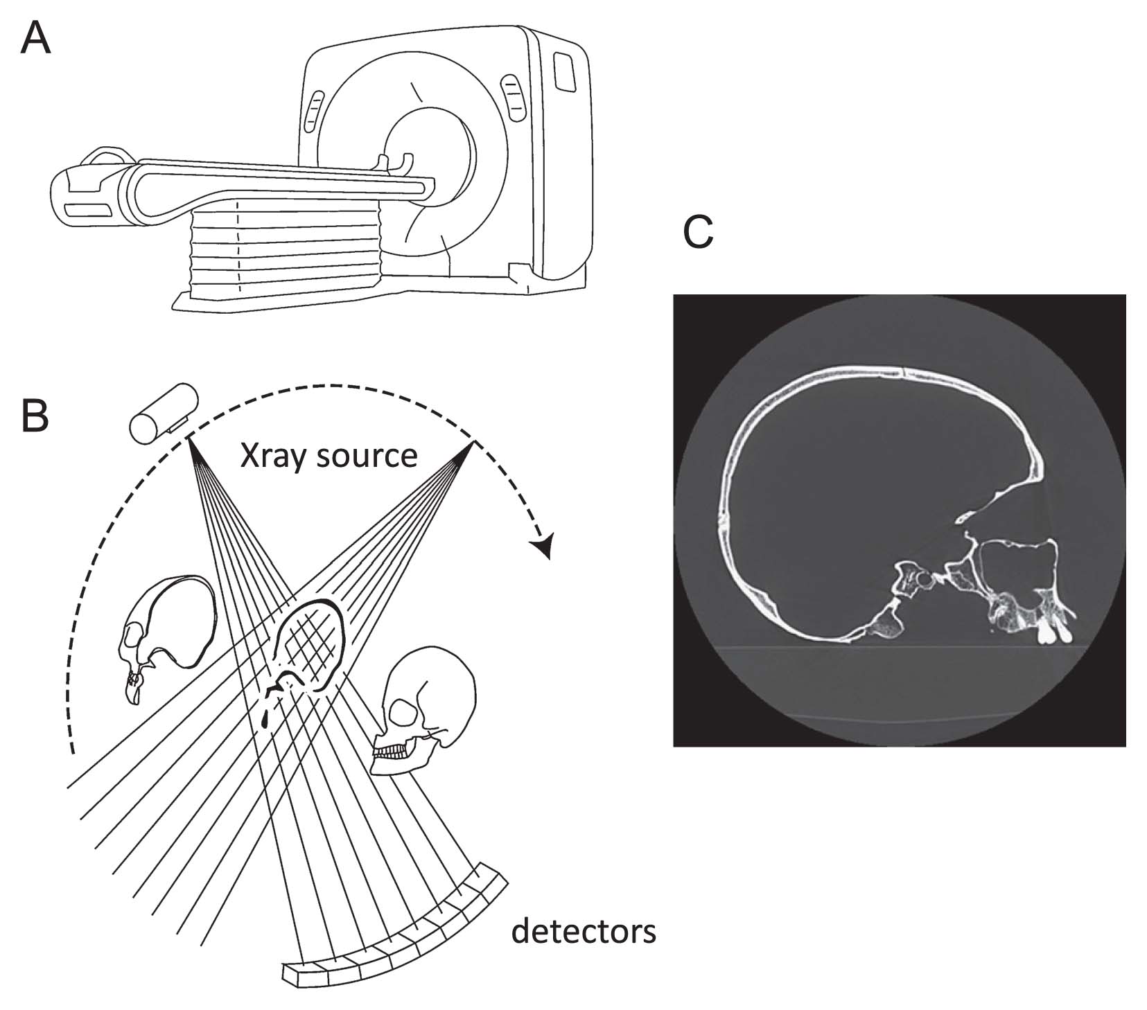
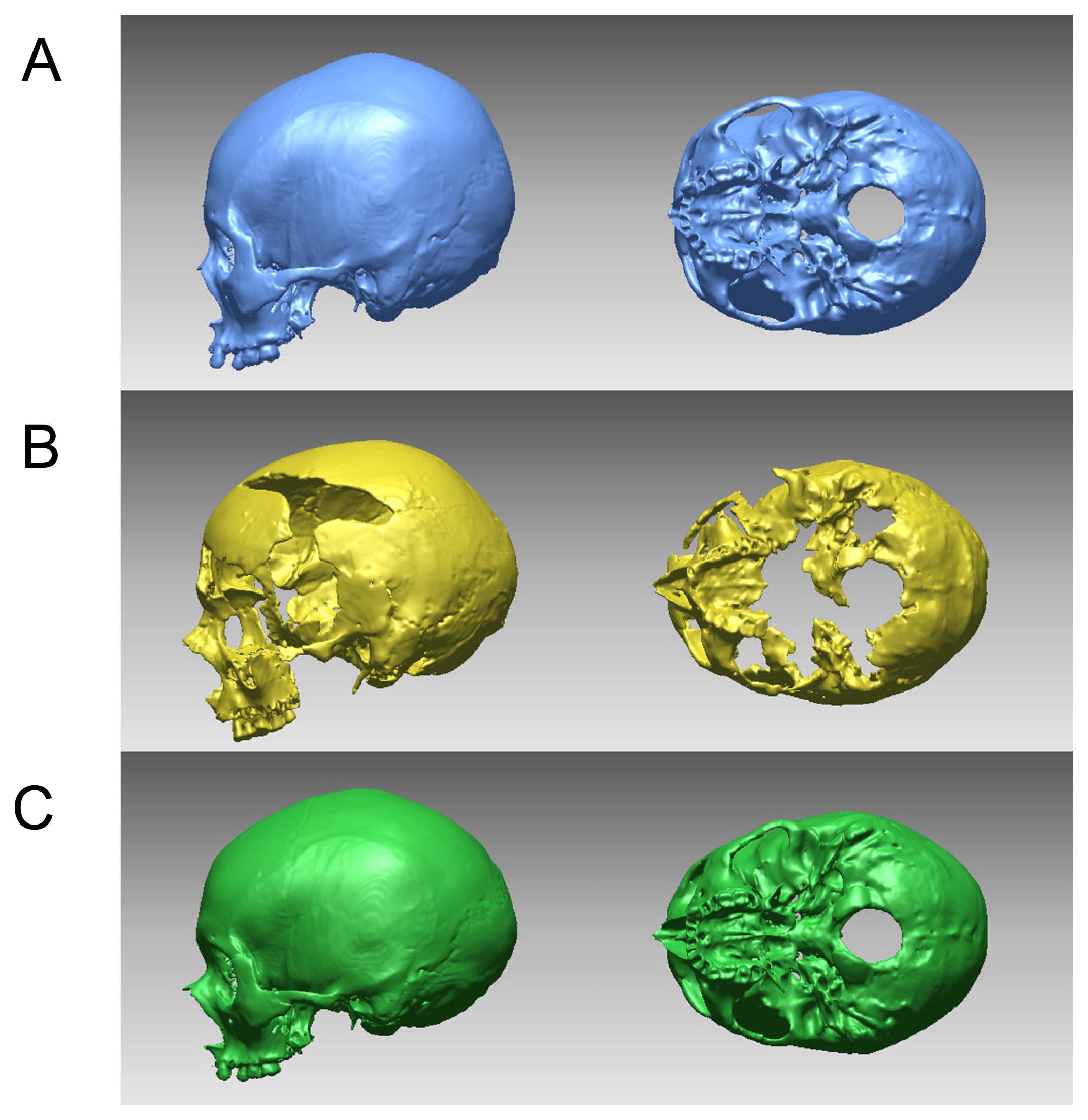
An X-ray CT scanner comprises an X-ray source and an array of detectors that rotate around an object and generate a cross-sectional image based on differences in the attenuation of X-rays by different materials (Figure 2). If the object placed on a table is moved along the axis of rotation of the X-ray source and detectors, a series of cross-sectional images of the object are generated, and these can be assembled to create a three-dimensional (3D) image. From this stack of images, the object region is segmented and its 3D surface represented as a triangular mesh model (Figure 3). The CT scanner is thus essentially a data-acquisition device that captures both the external and internal structures comprising the 3D form of a specimen. The spatial resolution of medical CT is about 0.3 mm, which is usually adequate for morphological analysis of human crania.
Complete acquisition of a fossil cranium in a virtual space allows new reconstruction of the fossil cranium without damaging the original specimen. Using digital modeling, glue and plaster can be removed from the original specimen to separate out the fragments constituting the fossil cranium, allowing reassembly of these fragments. The reassembled cranium can then be geometrically or statistically interpolated for missing regions and corrected for deformations based on geometric processing technologies, such as a spatial warping techniques, if the reconstruction is conducted using a digital model.
Assembly of Cranial Fragments
Fossil crania are often fragmented and are thus usually recovered in multiple scattered pieces. To conduct morphological analysis, these pieces must somehow be assembled like a jigsaw puzzle based on anatomical information (Figure 4). The first reports on the assembly of cranial fossil fragments in virtual space were made in 1995, with the restorations of a Middle Pleistocene hominid cranium excavated from two fossil sites in Morocco (Salé and Thomas Quarry) and that of a Neanderthal child (Devil’s Tower) described by Kalvin et al. (1995) and Zollikofer et al. (1995), respectively. Since then, digital reconstructions of fossil crania have become widespread, bringing substantial results and benefits. For example, Ponce de Léon and Zollikofer (2001) restored fossil crania of Neanderthals ranging in age from infant to adult using the same computer-assisted method, and cross-sectionally investigated ontogenetic changes in cranial shape. They demonstrated that the characteristic features of Neanderthal skulls, such as the vertically short and anteroposteriorly long cranium, pronounced supraorbital ridge, inclined forehead, and large nasal region, emerged as early as the fetal stage and such morphological differences between Neanderthals and modern humans were retained in adults because their growth trajectories are roughly parallel. Crania of early hominids, such as Sahelanthropus tchadensis and Ardipithecus ramidus, have also been reconstructed digitally in virtual space (Zollikofer et al., 2005; Suwa et al., 2009), and the significance of such virtual reconstructions is now well established. In these reconstructions, however, the cranial fragments were assembled manually by moving and rotating each piece into anatomical positions by manipulating the computer mouse.

Automated reassembly of fractured objects has been investigated in the field of computational geometry. For example, methods of reassembling objects from fragments have been proposed based on the geometric similarity of fracture surfaces (e.g. Papaioannou et al., 2002; Huang et al., 2006), as automated reconstruction is essentially viewed as a pattern-matching problem. Such mathematical approaches are now applied to 3D cranial reconstruction. For example, a mathematical attempt to reconstruct a multifractured mandible based on the automatic registration of opposable fracture surfaces has been proposed (Chowdhury et al., 2009). More recently, an automatic cranial assembly based on a template cranium to guide fragment reassembly using the heat kernel signature has been proposed (Yu et al., 2012). However, fractured surfaces of fossil cranial fragments are typically thin and damaged by erosion. Furthermore, not all fragments of fossil crania are usually present. Registration techniques based on the correspondence of fracture surfaces are thus not generally applicable for reassembling cranial fossils. In the field of archaeology, Willis and Cooper (2008) attempted computational reassembly of fragments of ceramic pots by exploiting features of axial symmetry. However, such simple geometrical constraints that can be exploited for reassembly are usually not present for human crania.
For correct assembly of cranial fragments, our group is now attempting to develop a computerized technique for assembling fossil cranial fragments based on 3D local shape information, i.e. the smoothness of the joints between fragments (Kikuchi and Ogihara, 2013). Specifically, we approximate the surfaces of cranial fragments using Bézier surfaces to extrapolate to the fragments and mathematically predict the surface shape of adjacent fragments. The positions and orientations of these fragments are then calculated by minimizing fitting errors, enabling continuous and smooth alignment of the fragments. In practice, however, correct assembly of an entire skull based solely on the local smoothness criterion is probably difficult. To achieve globally consistent, anatomically reasonable assembly of cranial fragments, use of a template cranium might be necessary.
Correction of Deformation
Due to compaction and diagenesis, unearthed cranial fossils have often undergone plastic deformation. Digital correction of such deformation must therefore be attempted for fossil crania. For example, Ponce de Léon and Zollikofer (1999) attempted to correct deformation of a Neanderthal skull (Le Moustier 1) by assuming the deformation to be in the form of a linear transformation. A digital model of the skull was mathematically undeformed to remove vertical compression, as illustrated in Figure 5. Gunz et al. (2009) proposed another method to correct deformation using a mirror image and applied this method to the restoration of the Arago XXI cranium; a mirror-reflected model of the original specimen was generated and the average of the original and reflected shapes was calculated to correct for shear deformation (Figure 6), assuming bilateral symmetry of the cranium. In both cases, deformation was assumed to be in the form of linear uniform compression or a shear process in order to correct for taphonomic deformation of the cranium.

Linear transformation of a 3D digital cranial model is expressed as a combination of translation, rotation, scaling, and shear operations. This is called a 3D affine transformation and can be expressed as:
where pi is the position vector of the ith vertex on a cranial model, p̄i is the same position vector after the affine transformation, T is the 3 × 3 affine transformation matrix, and q is the translation vector. This equation can also be expressed using a homogeneous transformation matrix as:
|
[
p
¯
i
1
]
=
[
T
q
0
1
]
[
p
i
1
]
. | (2) |
Matrix T can be expressed by multiplying the rotational matrix R, the scaling matrix M, and shear matrix S as:
There are many ways to express the rotational matrix, depending on the order of rotation around the three orthogonal axes. One possible form is:
|
R
=
R
x
R
y
R
z
=
[
1
0
0
0
cos
θ
-
sin
θ
0
sin
θ
cos
θ
]
[
cos
φ
0
sin
φ
0
1
0
-
sin
φ
0
cos
φ
]
[
cos
ψ
-
sin
ψ
0
sin
ψ
cos
ψ
0
0
0
1
]
, | (4) |
where θ, φ, and ψ are the rotational angles with respect to the x, y, and z axes, respectively. The scaling matrix M represents scaling along the orthogonal axes as:
|
M
=
[
a
0
0
0
b
0
0
0
c
]
, | (5) |
where a, b, and c are the zoom factors along the x, y, and z axes, respectively. The share matrix S can be written as:
|
S
=
[
1
d
e
0
1
f
0
0
1
]
, | (6) |
where d, e, and f are the shearing factors in the xy, xz, and yz planes, respectively. Linear spatial deformation can therefore be represented by six parameters, a, b, c, d, e, and f, since the three rotational (θ, φ, ψ) and three translational (q) parameters of the affine transformation represent changes in the orientation and position, respectively, of the cranial model in 3D space, but not the change in its shape. Figure 7 shows the deformation of a human cranium represented by M and S. Therefore, by appropriately estimating M and S and applying the inverse transformations of M and S, the deformed skull can be mathematically undeformed.

It must be noted, however, that deformation of fossil crania is generally a non-homogeneous process. To represent a non-homogeneous deformation process, a more complex model of deformation is necessary. One way to describe such non-homogeneous transformation before and after taphonomic deformation is to introduce a non-linear spatial transformation function such as a thin-plate spline (TPS) function (Bookstein, 1989).
The TPS function describes non-homogeneous mapping between two sets of landmarks (Figure 8). Let x1, x2, …, xK represent K landmark coordinates before transformation, and x̄1, x̄2, …, x̄K represent these same landmark coordinates after transformation. Using matrix representation, these can be written as:
|
Q
=
[
1
x
1
T
1
x
2
T
⋮
⋮
1
x
K
T
]
,
V
=
[
x
¯
1
x
¯
2
⋯
x
¯
K
]
, | (7) |
where Q is a (K × 4) and V is a (3 × K) matrix, and K is the total number of the landmarks used to describe the TPS function. Using the TPS function, mapping from Q to V can be described by a linear combination of basis functions as:
|
V
T
=
PW
+
QA
P
=
[
U
(
r
1
,
1
)
U
(
r
1
,
2
)
⋯
U
(
r
1
,
K
)
U
(
r
2
,
1
)
U
(
r
2
,
2
)
⋯
U
(
r
2
,
K
)
⋮
⋮
⋱
⋮
U
(
r
K
,
1
)
U
(
r
K
,
2
)
⋯
U
(
r
K
,
K
)
]
,
r
i
,
j
=
‖
x
i
-
x
j
‖ | (8) |
where W and A are the (K × 3) and (4 × 3) coefficient matrices and ri,j is the Euclidean distance between the ith and jth landmarks. In this matrix, U(ri,j) is the basis function. The first term on the right-hand side of Equation (8) (i.e. PW) represents a non-linear transformation, whereas the second term (i.e. QA) represents a linear (affine) transformation. The basis function used for the 3D TPS function is described as:
|
U
(
r
i
,
j
)
=
r
i
,
j
. | (9) |
Equation (8) must be solved for W and A in order to define the mapping function. However, the solution is indeterminate because the number of unknown parameters in W and A is greater than the number of equations. Hence, the equation is solved given the following additional condition:
which minimizes the magnitude of the non-linear transformation component. The simultaneous equations
|
[
V
T
0
]
=
[
P
Q
Q
T
0
]
[
W
A
]
=
L
[
W
A
] | (11) |
can now be solved for a unique set of W and A as:
|
[
W
A
]
=
L
-
1
[
V
T
0
]
. | (12) |
The mapping function is therefore defined as:
|
s
¯
i
T
=
f
(
s
i
)
=
[
U
(
r
i
,
1
)
U
(
r
i
,
2
)
⋯
U
(
r
i
,
K
)
]
·
W
+
(
1
s
i
T
)
·
A
, | (13) |
where si and s̄i are the coordinates of the ith vertex of a triangular mesh describing the cranial model before and after transformation. This equation describes the mapping from Q to V such as to minimize the bending energy of spatial deformation before and after transformation, which can be defined as:
|
E
=
∫
∫
∫
R
3
{
(
∂
2
f
∂
x
2
)
2
+
(
∂
2
f
∂
y
2
)
2
+
(
∂
2
f
∂
z
2
)
2
+
2
(
∂
2
f
∂
x
∂
y
)
2
+
2
(
∂
2
f
∂
x
∂
z
)
2
+
2
(
∂
2
f
∂
y
∂
z
)
2
}
d
x
d
y
d
z
. | (14) |
Figure 8 shows an example of non-homogeneous deformation using the TPS. Here, the spatial deformation of a grid box is represented by the translation of one of nine coordinate locations. As the deformation of the grid shows, the smooth spatial deformation is successfully represented. If many landmarks are moved to represent deformation, more complex non-homogeneous deformation can be described. The TPS function therefore approximates the displacement vector field defined by the assigned correspondence of landmarks, and can be used to estimate a displacement vector at each of the intermediate mesh vertices between landmarks. The shape transformation of the entire human cranium due to deformation (or undeformation) can thus be described using the same function. Figure 9 shows an example of human cranial deformation from cranium A to B. By obtaining the 3D coordinates of corresponding landmarks (i.e. Q and V), the spatial deformation from A to B can be defined using the TPS function, and cranium A can be deformed to match cranium B. It must be noted, however, that even if cranium A is deformed back using the same framework, the resultant cranium would not be identical to the original shape of cranium A, since the TPS transformation is not invertible, particularly if the deformation is large. For a globally continuous, invertible transformation (diffeomorphic mapping), a different deformation model must be employed.


Using this function, Ogihara et al. (2006) proposed a method to correct non-homogeneous deformation of a cranium based on bilateral symmetry. If a skull is intact, cranial landmarks on the midsagittal plane basically lie on the same plane and each bilateral landmark pair should be symmetrical to each other with respect to this plane. However, if the cranium is subjected to deformation, this geometrical relationship does not hold. The positions of the landmarks were therefore first moved to the new locations so that the midsagittal landmarks are coplanar and bilateral landmark pairs are symmetrical. The non-homogeneous mapping between the two corresponding sets of landmarks was then represented using the TPS function, and the entire shape of the cranium was transformed for undeformation. Figure 10 shows the result of correction of a fossil cranium of the Miocene hominoid Proconsul heseloni. If deformation of the skull is eliminated by symmetrization, the damaged portion of the skull can be replaced with the reflection of the opposite side.

However, if, the skull is deformed, whether the deformation is homogeneous or not, in the direction parallel to the midsagittal plane as in the case of Proconsul, the proposed method based on bilateral symmetry would not suffice. A cranium that has suffered linear shear deformation as in Figure 7E, for example, would not be corrected based on bilateral symmetry, as it remains symmetrical with respect to the midsagittal plane.
One possible solution for this problem is the use of a reference template for correction of deformation. To go to the extreme, however, the deformed cranium can be completely warped to a template cranium used as a reference by defining a spatial transformation function such as TPS. To correct for taphonomic deformation of a fossil cranium, the taphonomic component of the fossil’s shape variance should be selectively eliminated from the original deformed cranium. For this, our group is now developing a method to mathematically isolate the taphonomic deformation of fossil crania based on principal component analysis. The shape difference between a reference template cranium and a deformed fossil cranium can be assumed to consist of two main components: a taphonomic deformation component; and an intraspecific shape variability component. Because the intraspecific shape variability can be assumed to differ in characteristics from the shape change occurring due to taphonomic deformation, the taphonomic component, or at least a part of it, could be extracted and selectively eliminated using principal component analysis. Our preliminary results for such decomposition have been quite encouraging.
Interpolation of Missing Parts
Anatomically accurate interpolation of missing parts in fossil crania is important for correct estimation of brain morphology based on cranial shape information. Several methods can be used to interpolate missing parts of assembled fossil crania. The simplest method is to exploit bilateral skeletal symmetry; in other words, a mirror-image model is generated from the well-preserved undistorted side of a specimen to interpolate the other side. Specifically, a median sagittal plane is calculated by least-squares fit based on coordinates of midsagittal anatomical landmarks and midpoints of bilateral landmark pairs. A plane-symmetrical model of the original is then generated to interpolate the coordinates of the missing parts on the other side (Figure 11). Conroy et al. (1998), for example, reconstructed an Australopithecus africanus cranium (Stw 505) using a mirror image.

Nevertheless, interpolation based on bilateral symmetry is not applicable if morphological information is missing on both sides. In such cases, deficiencies can be estimated and interpolated based on reference data, in turn based on information from the intact portion of the deficient cranial form. Two methods have been proposed for such interpolation: geometric interpolation using a spline function; and statistical interpolation using multivariate regression (Gunz et al., 2009).
Geometric interpolation using a spline function interpolates a missing part based on data mapped from a complete reference specimen. Specifically, the reference cranial form is first registered (aligned) with the deficient cranial form using the common existing landmarks by generalized Procrustes analysis (superimposition of landmark coordinates based on a least-squares method). Matrices W and A of the TPS function (Equation (8)) are calculated to define the mapping function from the reference to the target damaged specimen. Using this TPS function, the reference cranial form is warped to the damaged form and the region of the warped reference cranium corresponding to the missing portion is used to reconstruct the missing parts. The existing portion of the specimen to be reconstructed is therefore used to define the mapping function, and the corresponding portion of the complete specimen is then mapped to the partial specimen in order to reconstruct the missing parts. Figure 12 shows the results of interpolation for a male cranium excavated from the Himrin Basin in Iraq (Ogihara et al., 2009), using a modern Japanese cranium as a reference. Here we calculated the mapping from the modern Japanese cranium to the Himrin cranium using the TPS function in order to interpolate the parts missing from the Himrin cranium. This method yields anatomically natural, morphologically consistent interpolation of the missing parts (Figure 12). This technique is widely used for actual reconstructions of cranial fossils, such as the cranial morphology of Paranthropus boisei OH5 (Benazzi et al., 2011) and H. habilis KNM-ER-1813 (Benazzi et al., 2014).
However, it must be noted that the results of interpolation vary depending on the reference cranium used for interpolation. Using modern human and ape crania as references, Gunz et al. (2009) attempted to reconstruct the cranial morphology of H. erectus KNM-WT-15000 (Turkana Boy). They reported that the reconstructed results varied depending on the reference specimen used, particularly in the orbit and glabellar regions. The accuracy of interpolation also depends on the size and place of the defect. We virtually created human crania with missing portions and the defects were re-estimated with their true values using the TPS interpolation. The mean prediction errors were found to be about 1 and 3 mm for the small and large holes, respectively, in the neurocranium, and the errors were found to be worse in the basicranium (Amano et al., 2014). Neeser et al. (2009) also noted that geometric interpolation using TPS resulted in comparatively larger errors in estimating the shapes of missing portions over large areas. Furthermore, the number and distribution of the landmarks used to calculate the TPS function also affect the prediction error. To achieve precise estimation, many landmarks and semi-landmarks must be obtained, particularly in the vicinity of the defect.
On the other hand, statistical interpolation based on multivariate regression is a method for estimating missing coordinates based on a sample of complete specimens as a reference dataset. Multivariate regressions are calculated with the missing coordinates as dependent variables and other remaining coordinates as independent variables. These equations are then applied to predict the missing coordinates. The inter-landmark morphology of the missing portion is subsequently calculated using the TPS function describing a mapping from the reference form to the damaged cranium. For example, Weaver and Hublin (2009) estimated the position of the sacrum in a Neanderthal pelvis (Tabun 1) based on human pelvis morphological data, using the expectation-maximization algorithm for the estimation of regression coefficients.
To compute a multivariate regression analysis, the number of samples in the reference dataset has to exceed the number of landmark coordinates used as independent variables. However, the number of reference specimens that can be used for analysis is often limited, although more landmark coordinates are certainly necessary to precisely capture the morphological characteristics of each cranial specimen. Previously, Neeser et al. (2009) employed principal component analysis to reduce the number of independent variables used in the estimation of missing landmarks. However, a certain amount of morphological variance is certainly lost in such data reduction.
We are currently attempting to develop a method to statistically interpolate missing coordinates of human crania based on multivariate regression analysis using a small number of cranial specimens (Amano et al., 2014). In multivariate regression analysis, if the number of the reference dataset is smaller than the number of landmarks, the problem becomes under-constrained, hindering the use of multivariate regression analysis for the interpolation of missing parts in fossil crania. Nevertheless, such ill-posed problems can be made well-posed if the problem is regularized by introducing an additional constraint, in the form of a norm-minimization criterion to compute the regression coefficients. Our preliminary results demonstrated that the prediction errors were generally smaller than or equal to those estimated by the geometric interpolation method.
Towards the Restoration of Brain Morphology
What we will have in hand to investigate the Neanderthal brain after reconstruction are the crania of Neanderthal individuals, but not the brains themselves. To estimate the brain morphology of Neanderthals based on these fossil crania, establishment of possible morphological correspondences between cranial and brain morphologies based on living humans is essential. Such correspondence is critically important for estimating brain morphology from cranial shape; if no correspondence existed between cranial and brain forms, the estimation of brain morphology from a fossil cranium would not be possible.
In order to investigate this, we started to analyze head CT and magnetic resonance imaging (MRI) scans of adult human participants. CT and MRI images from the same participants were first registered to the same coordinate frame, so as to maximize the mutual information criterion between the two images (Friston et al., 2006). Cranial, endocast and brain surfaces were then extracted from CT and MRI, respectively, to detect possible morphological correspondences among the three (Figure 13). Generally, if the cranium is asymmetrical and high, for example, the enclosed brain will be asymmetrical and high to the same degree, indicating that brain morphology generally corresponds to the surface of the cranial endocast that encloses the brain. Consequently, the global shape of the brain in a fossil cranium can be roughly estimated computationally using a spatial deformation function. Spatial mapping from a template cranium (with its enclosed brain) to a fossil cranium is defined using a spatial deformation function, and this function is applied to deform the template brain to estimate the shape of the brain inside the fossil cranium.

For this, a mathematical framework from the field of computational neuroanatomy may be useful (Kochiyama et al., 2014; Tanabe et al., 2014). To statistically compare differences in brain activities from functional MRI, 3D volumetric data from the brain of each participant must be transformed (warped) onto a standard template, since large individual variations exist in the size and shape (i.e. spatial pattern of sulci, gyri, etc.) of the brain. The Statistical Parametric Mapping (SPM) software package was therefore developed in the field of computational neuroanatomy (Friston et al., 2006). In this software package, the spatial transformation (registration) of brain images is achieved using the Diffeomorphic Anatomical Registration Through Exponentiated Lie Algebra (DARTEL) algorithm (Ashburner, 2007). Here the deformation function is represented by the temporal evolution of deformation from t = 0 to 1 as:
|
s
¯
=
Φ
(
s
)
=
∫
t
=
0
1
u
(
s
)
d
t
, | (15) |
where s and s̄ are the position vectors before and after deformation, u is a time-invariant single flow field (velocity field) describing the deformation, and Φ(s) is the mapping function from s to s̄. The velocity field is represented by a linear combination of B-spline basis functions as:
|
u
(
s
)
=
∑
i
v
i
b
i
(
s
)
, | (16) |
where vi is the ith coefficient of the vector v, and b(s) is the ith B-spline basis function at position s. For registration, therefore, the vector v that parametrizes the deformation should be estimated by simultaneously minimizing the mean-squared difference between the individual image g and the template image f, and applying a deformation smoothing measure as:
|
E
(
v
)
=
1
2
∑
i
=
1
(
f
(
s
i
)
-
g
(
s
¯
i
)
)
2
+
ɛ
(
Φ
)
, | (17) |
where f(si) and g(s̄i) are the voxels corresponding ith position vector in the template and the warped images, respectively, and ɛ(Φ) is the deformation smoothing measure such as the linear elastic energy (Ashburner, 2007). Figure 14 is a schematic showing a deformation from a modern human endocranium to that of a Neanderthal using the DARTEL framework. Here the deformation between the two endocasts is successfully represented by a smooth deformation field represented by Equation (15). Using this framework, the reconstructed fossil endocasts can be spatially deformed to the modern human endocasts segmented from the results of MRI. Modern human brains segmented from the MR image can then be inverse-transformed to estimate the brain morphology best fitting the crania, as this deformation function is diffeomorphic and hence invertible. See Ashburner (2007) for more details of the calculation method and diffeomorphic deformation.

If this process goes well, we can examine differences in brain anatomy based on computational morphometric analyses such as voxel-based (e.g. Ashburner and Friston, 2000) and deformation-based morphometry (e.g. Ashburner et al., 1998). What also becomes feasible with the proposed framework is the comparison of extracted differences in brain morphology between Neanderthals and modern humans with brain regions corresponding to ‘learning abilities’ extracted based on functional MRI studies and associated meta-analyses.
However, whether the spatial patterns of the gyri and sulci of the brain can be estimated from the shape of the cranium remains unclear. To achieve detailed inferences of brain morphology based on cranial shape, more microscopic correspondences between cranial and brain morphology must also be explored and investigated in future studies (Bruner et al., 2014).
Conclusion
This paper has discussed computerized approaches for the digital restoration of fossil crania and introduces future directions for our project towards reconstructing the brain morphology of Neanderthals. Restoring the original antemortem appearance of a fossil brain is actually a very challenging, ill-posed problem. Further progress in computer-assisted methods for the morphological restoration of fossil crania and brains is certainly indispensable towards understanding differences in brain morphology and learning ability between Neanderthals and early modern humans.
Acknowledgments
We wish to express our sincere gratitude to Takeru Akazawa (Kochi Institute of Technology) for giving us the opportunity to participate in this research project and for his unstinting guidance and support throughout the course of the present study. We are also grateful to Hiromasa Suzuki (University of Tokyo), Osamu Kondo (University of Tokyo), Yasushi Kobayashi (National Defense Medical College), Hajime Ishida (University of the Ryukyus), Masato Nakatsukasa (Kyoto University), Takashi Michikawa (Osaka University), Masaki Moriguchi (Chuo University), Daisuke Kubo (University of Tsukuba), and Emiliano Bruner (Centro Nacional de Investigación sobre la Evolución Humana) for collaborations in this research project. This study was supported by a Grant-in-Aid for Scientific Research on Innovative Areas “Replacement of Neanderthals by Modern Humans: Testing Evolutionary Models of Learning” from the Japanese Ministry of Education, Culture, Sports, Science and Technology.
References
- Amano H., Morita Y., Nagano H., Kondo O., Suzuki H., Nakatsukasa M. and Ogihara N. (2014) Statistical interpolation of missing parts in human crania using regularized multivariate linear regression analysis. In: Akazawa T., Ogihara N., Tanabe H.C. and Terashima H. (eds.), Dynamics of Learning in Neanderthals and Modern Humans, Vol. 2: Cognitive and Physical Perspectives. Springer, New York, pp. 161–169.
- Ashburner J. (2007) A fast diffeomorphic image registration algorithm. Neuroimage, 38: 95–113.
- Ashburner J. and Friston K.J. (2000) Voxel-based morphometry—the methods. Neuroimage, 11: 805–821.
- Ashburner J., Hutton C., Frackowiak R., Johnsrude I., Price C. and Friston K. (1998) Identifying global anatomical differences: deformation-based morphometry. Human Brain Mapping, 6: 348–357.
- Benazzi S., Bookstein F., Strait D. and Weber G. (2011) A new OH5 reconstruction with an assessment of its uncertainty. Journal of Human Evolution, 61: 75–88.
- Benazzi S., Gruppioni G., Strait D.S. and Hublin J.-J. (2014) Virtual reconstruction of KNM-ER 1813 Homo habilis cranium. American Journal of Physical Anthropology, 153: 154–160.
- Bookstein F.L. (1989) Principal warps—thin-plate splines and the decomposition of deformations. IEEE Transactions on Pattern Analysis and Machine Intelligence, 11: 567–585.
- Bruner E., de la Cuetara J.M., Masters M., Amano H. and Ogihara N. (2014) Functional craniology and brain evolution: from paleontology to biomedicine. Frontiers in Neuroanatomy, 8: 19.
- Chowdhury A.S., Bhandarkar S.M., Robinson R.W. and Yu J.C. (2009) Virtual multi-fracture craniofacial reconstruction using computer vision and graph matching. Computerized Medical Imaging and Graphics, 33: 333–342.
- Conroy G.C. and Vannier M.W. (1984) Noninvasive 3-dimensional computer imaging of matrix-filled fossil skulls by high-resolution computed-tomography. Science, 226: 456–458.
- Conroy G.C., Weber G.W., Seidler H., Tobias P.V., Kane A. and Brunsden B. (1998) Endocranial capacity in an early hominid cranium from Sterkfontein, South Africa. Science, 280: 1730–1731.
- Friston K., Ashburner J., Kiebel S., Nichols T. and Penny W. (2006) Statistical Parametric Mapping: The Analysis of Functional Brain Images. Academic Press, Amsterdam.
- Gunz P., Mitteroecker P., Neubauer S., Weber G.W. and Bookstein F.L. (2009) Principles for the virtual reconstruction of hominin crania. Journal of Human Evolution, 57: 48–62.
- Huang Q.X., Floery S., Gelfand N., Hofer M. and Pottmann H. (2006) Reassembling fractured objects by geometric matching. ACM Transactions on Graphics, 25: 569–578.
- Kalvin A.D., Dean D. and Hublin J.J. (1995) Reconstruction of human fossils. IEEE Computer Graphics and Applications, 15: 12–15.
- Kikuchi T. and Ogihara N. (2013) Computerized assembly of neurocranial fragments based on surface extrapolation. Anthropological Science, 121: 115–122.
- Kochiyama T., Tanabe H.C. and Ogihara N. (2014) Reconstruction of the brain from skull fossils using computational anatomy. In: Akazawa T., Ogihara N., Tanabe H.C. and Terashima H. (eds.), Dynamics of Learning in Neanderthals and Modern Humans. Vol. 2: Cognitive and Physical Perspectives. Springer, New York, pp. 191–200.
- Morita Y., Ogihara N., Kanai T. and Suzuki H. (2013) Quantification of neurocranial shape variation using the shortest paths connecting pairs of anatomical landmarks. American Journal of Physical Anthropology, 151: 658–666.
- Neeser R., Ackermann R.R. and Gain J. (2009) Comparing the accuracy and precision of three techniques used for estimating missing landmarks when reconstructing fossil hominin crania. American Journal of Physical Anthropology, 140: 1–18.
- Ogihara N., Nakatsukasa M., Nakano Y. and Ishida H. (2006) Computerized restoration of nonhomogeneous deformation of a fossil cranium based on bilateral symmetry. American Journal of Physical Anthropology, 130: 1–9.
- Ogihara N., Makishima H. and Ishida H. (2009) Geometric morphometric study of temporal variations in human crania excavated from the Himrin basin and neighboring areas, northern Iraq. Anthropological Science, 117: 9–17.
- Papaioannou G., Karabassi E.A. and Theoharis T. (2002) Reconstruction of three-dimensional objects through matching of their parts. IEEE Transactions on Pattern Analysis and Machine Intelligence, 24: 114–124.
- Ponce de León M.S. and Zollikofer C.P.E. (1999) New evidence from Le Moustier 1: Computer-assisted reconstruction and morphometry of the skull. Anatomical Record, 254: 474–489.
- Ponce de León M.S. and Zollikofer C.P.E. (2001) Neanderthal cranial ontogeny and its implications for late hominid diversity. Nature, 412: 534–538.
- Suwa G., Asfaw B., Kono R.T., Kubo D., Lovejoy C.O. and White T.D. (2009) The Ardipithecus ramidus skull and its implications for hominid origins. Science, 326: 68.e1–7.
- Suzuki H. and Takai F. (1970) The Amud Man and His Cave Site. Keigaku Publishing, Tokyo.
- Tanabe H.C., Kochiyama T., Ogihara N. and Sadato N. (2014) Integrated analytical scheme for comparing neanderthal’s brain to modern human brain using neuroimaging techniques. In: Akazawa T., Ogihara N., Tanabe H.C. and Terashima H. (eds.), Dynamics of Learning in Neanderthals and Modern Humans. Vol. 2: Cognitive and Physical Perspectives. Springer, New York, pp. 203–207.
- Weaver T.D. and Hublin J.J. (2009) Neandertal birth canal shape and the evolution of human childbirth. Proceedings of the National Academy of Sciences of the United States of America, 106: 8151–8156.
- Willis A.R. and Cooper D.B. (2008) Computational reconstruction of ancient artifacts. IEEE Signal Processing Magazine, 25: 65–83.
- Wind J. (1984) Computerized x-ray tomography of fossil hominid skulls. American Journal of Physical Anthropology, 63: 265–282.
- Yu W., Li M. and Li X. (2012) Fragmented skull modeling using heat kernels. Graphical Models, 74: 140–151.
- Zollikofer C.P.E., Ponce de León M.S., Martin R.D. and Stucki P. (1995) Neanderthal computer skulls. Nature, 375: 283–285.
- Zollikofer C.P.E., Ponce de León M.S., Lieberman D.E., Guy F., Pilbeam D., Likius A., Mackaye H.T., Vignaud P. and Brunet M. (2005) Virtual cranial reconstruction of Sahelanthropus tchadensis. Nature, 434: 755–759.


