Recent Advancements in Hairpin Welding: Manufacturing and Properties
Article ID: 665
Details
Article ID: 665
In the last decade or so, the technology in electric vehicles has advanced significantly including increased battery range, faster charging, wireless charging, battery management, battery weight reduction, power and efficiency of the electric motor, and many others. There are two main components in the electric motor, namely, rotor and stator. Hairpins are critical part of a stator. They are made of pure copper. One of the important processes in the fabrication of a stator is connecting/welding the individual hairpin. In this paper, a brief description of hairpin manufacturing based on the published articles and the results from more recent investigation, particularly the welding aspect is provided.
1 College of Engineering and Applied Sciences, Western Michigan University, USA
2 Joining and Welding Research Institute, Osaka University, Japan
3 Dept. of Mechanical Engineering, National Chung Cheng University, Taiwan
E-mail: tim.pasang@wmich.edu (Tim PASANG)
ABSTRACT
International Journal of the Society of Materials Engineering for Resources, Vol. 27, No. 1, 665
Received March 6, 2025
Accepted for Publication April 8, 2025
Advanced Publication by J-STAGE
DOI:
1 INTRODUCTION
In electric vehicles, the function of battery packs is to store energy. The energy is then used to drive an electric motor. The electric motor then converts the energy into mechanical rotation to power the electric car. The electric motor has two components, i.e. rotor and stator. A stator contains the so-called hairpins (Figures 1 and 2) which are usually made of pure copper. These hairpins - typically rectangular for better fill factors - are very critical to supply magnetic field to rotate the rotor and torque to the wheels. Therefore, they must be strongly connected to each other and reliable. An electric motor (Figure 1) may have around 120 or more hairpin weld joints [1]. Several welding techniques have been employed to connect hairpins, and some new methods are being explored to increase the strength, power and improve efficiency. The hairpins must also have low electrical resistivity or electrical resistance, therefore, a very good connection, i.e. deeper welding depth (without any porosity) is required.

Figure 1. A diagram showing components in an electric motor. Note the hairpin location on the stator [2].

Figure 2. A close-up view showing hairpins on the stator [3]
2 HAIRPIN MANUFACTURING
Hairpins for electric vehicles are usually made of pure copper due to their high electrical conductivity. The whole steps from forming up to winding in a stator is presented in Figure 3. The steps are as follows:
1. prepare coated copper wires at a certain length,
2. stripping or removal of the insulation at the ends of the wires (usually by laser process),
3. forming/shaping,
4. assembly/inserting into the stator,
5. twisting,
6. contacting/welding.

Figure 3. Manufacturing and winding process of a hairpin into a stator including the welding at the end [4].
The quality of welding is critical as the weld joints must withstand vibrations and produce the required magnetic field, and therefore, they must be mechanically strong too. According to Kuntz [5], there are at least three common methods to weld the hairpins, i.e. (1) micro TIG welding, (2) resistance brazing and (3) laser welding. In this paper, only laser welding technology is reviewed and presented.
3 HAIRPIN WELDING: PRESENT AND FUTURE
A number of recent published articles on hairpin welding has been summarized in the following. D’Arcangelo et al. [6] employed various laser welding mechanisms with wavelength ranging from 515 nm (green laser) to 1070 nm (near infrared) and laser power between 3 and 6 kW to weld coppper wire with a dimension of 2.66 mm x 3.87 mm. The experiments with near infrared showed better penetration, hence, higher force to break the weld joints.

Figure 4. Macrographs showing weld joint of hairpins with various laser source [6]
Dimatteo et al. [7] employed a continuous wave 3.0kW Yb: Fiber laser near infrared with a wavelength of 1070 nm to weld copper wire with cross sectioal area of 7 mm2. The power used ranged from 1500 W to 2500 W. Figure 5 shows the optical micrographs of the hairpin weldment cross section. The presence of porosity will increase the resistance of the hairpin, and may cause over heating and or/arcing.

Figure 5. Cross-section of welded hairpin samples by Dimatteo et al. [7]
Tang et al. [8] conducted spot welding of pure copper hairpins using a blue laser with the idea of improving weld quality and efficiency compared with the conventional infrared laser. The sample cross sectional area was 8 mm2. The wavelength of this blue laser was 450 nm, and the power employed was 1950 W with welding time ranging from 0.3 seconds to 1.1 seconds. The optical microscopy images of the cross sections are shown in Figure 6. The optimum result was obtained with 0.7 seconds.
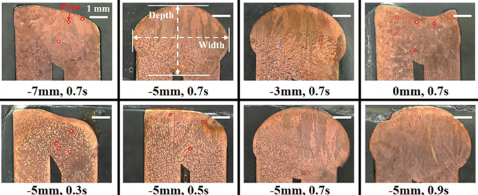
Figure 6. Cross-sections of welded hairpin samples by Tang et al. [8]
Ning and Zhang [9] performed a non-contact ultrasonic-assisted laser welding with power of 1200-1500 W on samples with cross-section of 4 mm2 with time of 2-6 seconds. The authors claimed that a welding time of 5 seconds produced a good weld joint and good repeatability (Figure 7).

Figure 7. Cross-section of welded hairpin samples by Ning and Zhang [9].
Toth et al. [10] conducted electron beam welding on two different pure copper, namely (i) Cu-OFE (oxygen free), and (ii) Cu-ETP (some small amount of oxygen) samples with a dimension of 4.3 mm x 2.33 mm (10.02 mm2) with a Electron Beam Welding (EBW) machine that has a maximum power of 15 kW. Figure 8 shows the cross-sections of the welded hairpins. The Cu-OFE samples showed very little porosity compared with the Cu-ETP samples.

Figure 8. Cross sections of welded hairpins (a) Cu-OFE, and (b,c) Cu-ETP samples [10].
Glaessel et al. [1] managed to obtained a weld depth of up to 4.1 mm with various amount of porosity depending on the parameters used (Figure 9). The authors were also able to establishe a relationship between the weld depth and elecrical resistance (Figure 10).

Figure 9. Cross section of samples produced by Glaessel et al. [1]

Figure 10. Relationships between welding depth and electrical resistance [1]. See also Figures 5 and 9.
A partnership between Joining and Welding Research Institute (JWRI), Osaka University and the College of Engineering and Applied Science (CEAS), Western Michigan University enables them to step-up the research on hairpin welding. Recently, a number of hairpin welding projects were started, first with a cross section of 7.5 mm2 (experiments #1) and 4.7 mm2 (experiments #2) as shown in Figure 11. This research involves the use of both infrared and blue diode laser. These investigations showed very promising results. The following factors were investigated including, weld depth and porosity by means of cross sectional metallography, electrical resistivity through four -point probe and strength via peel testing.

Figure 11. Set-up of experiments #1 and #2
The difference between experiments #1 and # 2 was not only the size of the samples, but also the sample preparation. On the Experiments #1 (Figure 12a), the insulation material was removed manually. In ddition, the samples were welded prior to bending and peel testing. On experiments #2 (Figure 12b), the insulation materials were removed by laser processing. Prior to welding, the samples were bent to avoid any additional work on the samples before they were peel tested. The cross-sectional metallography of samples form both experiments #1 and 2 are presented on Figure 13. On both experiments, the resistivity of all samples were measuresd using the four-point probe mechanism (Figure 14). The peel testing were performed according to the ISO 14270 standard [11]. The geometry of the sample is shown in Figure 15.

(a) (b)
Figure 12. Example of welded hairpin samples from experiments #1 (a) a combination of IR_P of 1000 W with BDL_P of 750 W for 0.6 seconds – left, and IR-only with P of 1300 W for 0.6 seconds – right, and (b) from experiments #2 with of IR_P of 1300 W combined with BDL_P of 1200 W for 0.15 seconds.

Figure 13. Cross-sections showing weld quality and depth from (a) experiments #1, and (b) experiments #2. Note: there is no evidence of defects presence.

Figure 14. Resistivity measurements with a four-point probe.
From the resistivity measurements, it was suggested that the resistivity of the welded samples, both from experiments #1 and #2, were comparable to that of the unwelded/reference samples. For experiments #1, the reference sample had a resistivity of around 0.00019 Ω.cm while the resistivity of the welded hairpins was between 0.00024 to 0.0006 Ω.cm. For experiments #2, the resistivity of the reference sample was around 0.00005 Ω.cm, while the welded hairpins had resistivity of around 0.00012 Ω.cm.
The maximum forces obtained through the peel testing (Figure 16) in these investigations were between 720 and 770 N. This is relatively higher than those reported by others, i.e. up to 400 N [6], 500 N [7], 716 N [9], and 320 N [12].

Figure 15. Peel testing sample geometry [7,11].

Figure 16. Welded hairpin sample (a) before and (b) after peel testing.
4 SUMMARY
The hairpin welding technology has advanced significantly in the last decade or so. More and more industries are now focusing on the use of laser technology, particularly the blue diode laser. As can be seen in this paper, blue diode laser shows very promising results especially if it is combined with the infrared laser.
REFERENCES