Abstract
In iron ore pellet production, an increased green pellet temperature has a positive influence on the straight grate induration furnace. Previous studies show that this can lead to both higher production capacity of the induration furnace and also reduced specific oil consumption. The aim of this study is to apply the process integration concept to analyze how to maintain a high green pellet temperature by using the available heat more effectively. The heat is today used for the indoor climate and is delivered by electricity boilers and a waste heat recovery boiler that is installed next to the induration furnace, using hot gases from the furnace to heat water. This work will however assume that one can use the heat from the waste heat recovery boiler to preheat the material stream. By optimizing the cold section of the pelletizing plant, using process integration and the mathematical modeling approach in combination with the newly developed Optimal Solution Space Method, the results show that it is possible to increase the green pellet temperature and also reduce the energy cost by using the available energy in a more efficient way. It is also showing that by retrofitting the system so that the waste heat from the waste heat recovery boiler is used to preheat the material stream, this also leads to reduced energy cost and also increased production of iron ore pellet since the temperature of green pellet will be higher.
1. Introduction
LKAB (Luossavaara-Kiirunavaara Aktiebolag) is a Swedish mining company and one of the world’s leading producers of upgraded iron ore products for the steel industry. LKAB have six operation facilities for iron ore pellet production, three in Kiruna, two in Malmberget and one in Svappavaara. In Malmberget, the final step in the process chain is the two pelletizing plants, based on the straight grate process. Due to the energy intense processes, LKAB is one of Sweden’s largest consumers of electricity. In 2010, the company accounted for about 1.5% of the total electricity consumption in Sweden.1) The total energy requirement in the production plants, in the form of electricity, fossil fuels and recovered surplus heat, amounted to around 4.1 TWh in 2010. LKAB is working actively to reduce the energy demand due to the energy costs and the awareness of the climate impact from fossils fuels. During the last decades, several studies with the aim to develop models of pelletizing processes has been done, both with focus of the so called grate kiln processes2,3,4,5,6,7) as well as straight grate processes.8,9,10,11,12,13) However, none of the studies are focusing on how to improve the pelletizing process by increasing the green pellet temperature. Previous studies and internal investigations show that increasing the temperature of the green pellet will have a positive influence on the induration furnace. The results show that if the green pellet temperature is increased by one degree centigrade, the production can be increased by around 4–5 ton/hour and the specific oil consumption decreases with around 0.1 liter/ton.14) Therefore, this work aims to develop a mathematical model to optimize the cold section of the pelletizing plant in order to maintain a high green pellet temperature by using the available energy sources more efficiently.
2. The Object of Process Modification
The LKAB facility in Malmberget consists of four main operation units, i.e. mine, sorting plant, concentrating plant and two pelletizing plants. The object studied in this work is one of the pelletizing plants, MK3, which can be divided into a cold and a hot section.
2.1. MK3 Pelletizing Plant – Cold Section
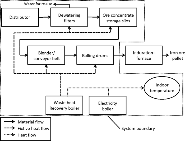
The cold section consists of various process units and the main aim for the cold section is to provide the hot section with the so called green pellet. Within the cold section, the material flow, originated from the concentrating plant, is processed through different units, i.e. slurry tank, distributor, dewatering filters, ore concentrate storage silos, blender/conveyor belt and finally the balling drums. Figure 1 is a schematic of the cold section and the corresponding process units.

The slurry, at a temperature of around 40°C and a flow rate of around 350 t/h, originated from the concentrating plant, is gathered in a slurry tank and then distributed into one of five dewatering filters where the aim is to reduce the water content in the slurry, from approximately 30 mass-% water content down to around 8 mass-%. This means that the thermodynamical properties of the pellet feed changes quite significantly after the dewatering filters, due to the reduced water content. The specific heat capacity of the material flow will be reduced from around 1.65 kJ/kg/K down to around 0.96 kJ/kg/K. The water which has been removed from the slurry is then redirected back to the concentrating plant for re-use. After the dewatering step, the ore concentrate is gathered into one of three storage silos, the purpose of these silos is just to ensure that the correct amount of ore concentrate is further processed in the process chain. After the storage silos, Bentonite is added into the ore concentrate as a binding agent in the production of iron ore pellet. The Bentonite is stored in an outdoor storage facility, meaning that the temperature of the Bentonite which is added into the ore concentrate is significantly colder than the ore concentrate itself, especially during the cold winter months. However, the amount of Bentonite which is added into the ore concentrate is only 0.5 mass-% of the ore concentrate flow. The effect on the temperature of the material flow can therefore be negligible. After the blender where the Bentonite has been added, the iron ore concentrate is fed into one of five balling drums. These drums are rolling the iron concentrate into centimeter sized spheres, or green pellet. The green pellet is then fed, via a conveyor-belt, into the straight grate induration furnace. Through the cold section, the temperature drop of the material flow varies depending on which unit the material passes through. The total temperature drop the material flow undergoes within the cold section of the pelletizing plant varies between around 6–12°C, depending on the indoor temperature.
2.2. MK3 Pelletizing Plant – Hot Section
The hot section consists basically of a 90 m long straight grate induration furnace where the final product of iron ore pellet is produced. The furnace is basically a huge heat exchanger where process gases passing through the pellet bed in a both up-draft and down-draft direction. The main purpose of the induration furnace is to dry, fire and cool the iron ore pellet. A waste heat recovery boiler is installed to the induration furnace. The waste heat recovery boiler is a heat exchanger which uses off gases from the induration furnace for heating of boiler water. The heat exchanger consists of two circuits, the hot air circuit and the boiler water circuit. When hot process gases of approximately 315°C are passing through the heat exchanger, the incoming recirculated boiler water, at a temperature of approximately 90°C, gets heated to around 110°C. The cooled process gas leaving the heat exchanger is directed into one of the exhaust gas fans. The heat from the recovery boiler is used as comfort heat for the factory buildings. Figure 2 shows a schematic of the MK3 straight grate induration furnace.

Within the straight grate induration furnace, many parameters will be affected by a higher green pellet temperature, which in turn will lead to improvements regarding both the specific oil consumption and the production capacity. Internal studies are showing that the durability of the green pellets is believed to be dependent on its temperature, a higher temperature of the material stream results in a more uniformly shaped pellet and also a smaller proportion of deformed pellet; this will improve the heat exchange between the pellet bed and the gas streams.15) Since the heat exchange in the bed will be improved with a lower pressure drop, this makes it possible to increase the travelling grate speed, or increase the bed height, which will lead to higher productivity.
3. Methodology
The process integration concept has been applied to design the cold section of the pelletizing plant, MK3. A mathematical optimization model based on Mixed Integer Linear Programming, MILP, has been developed. A common MILP modeling workflow is described in detail by Ryman et al.16) The equation editor used to model the cold section is called reMind,17) and commercial software, CPLEX,18) has been used as solver. This approach has earlier been used within different areas i.e. steel industry,19,20,21) heating systems,22,23) petrochemical industry24,25) and paper and pulp mill.26,27) A heat and mass balance has been carried out, including the main process units within in the chosen system. In this case, the system includes the cold section of the pelletizing plant (see Fig. 1), together with the electricity boiler and the waste heat recovery boiler which is installed next to the induration furnace.
In order to increase the time resolution in the model, a recently developed method, called Optimal Solution Space Method, OSSM,28) has been used. This method can be applied to increase the number of time periods i.e. the time resolution of a model with limited efforts. This method has been applied due to the fact that modeling results are heavily dependent on the chosen time resolution and important information might be lost if the time resolution is too low. In this study, a one week time resolution has been chosen for the optimization work, meaning that there are 52 time steps for every optimization case, one for every week of the year. Other time resolutions have also been tried in the modeling work of the cold section, both daily average and monthly average time resolutions. The monthly average time resolution could not cover the outdoor temperature fluctuations in a satisfying way, meanwhile the daily average time resolution showed similar results as the weekly average time resolution. Since the difference between the time resolutions of one week and one day were small, the case with a time resolution of one week was chosen, due to the reduced work load compared to a model with a daily average time resolution. Figure 3 shows the workflow when working with the solution space based method.

The principle is that a finite number of optimal solutions of the MILP formulation can be used to create any solution to the system by interpolation and the collection of finite solutions is referred to as an Optimal Solution Space, OSS, and the collection of equation systems that the OSS relies on as Problem Space, PS. In this study, the change in the heat demand for the indoor temperature is only dependent on the indoor- and outdoor temperature. An OSS that holds a finite number of optimal solutions under varying outdoor temperature can be used to calculate the optimal solution for any temperature by interpolation. This method is developed by Sandberg et al.28) where a thorough description of the method can be read. The OSS approach has been adapted by Wang et al.29) where the method has been used to analyze the potential of oxygen enrichment in an integrated steel plant.
3.1. Modeling of the Cold Section
3.1.1. The Objective Function
The model has been developed based on production data from 2011 and 2012. The data was collected from LKAB’s internal database as well as from onsite measurement. The onsite temperature measurement was carried out during the summer 2011 and the purpose of these measurements was to investigate how the temperature drop of the material flow was influenced by the indoor temperature. The result from the onsite measurement showed that the temperature drop in the material flow was significantly lower with a warmer indoor temperature. The relation between the temperature drop and the indoor temperature has been taken into account when designing the optimization model. The optimization model is run to minimize the total cost in the cold section of the pelletizing plant, MK3. The cost in this case corresponds to the energy cost of the electricity and the waste heat. Equation (1) shows the objective function used in the model.
|
minf(
x
)
=
c
el
m
el
+
c
heat
m
heat
| (1) |
Where f(x) is the objective function; c is the price of the energy carrier electricity and waste heat, m is the amount of the energy carrier electricity and waste heat. The electricity is the energy carrier used for heat production in the electricity boiler. The amount of heat used for the indoor climate is dependent of the indoor- and outdoor temperature. To maintain a high indoor temperature, this requires more energy, especially during the cold winter months. This leads also to increased energy costs. It was although difficult to put a price of the heat originated from the waste heat recovery boiler, but when discussing this with people working at the plant it was decided to set the price of the waste heat and electricity to 30 SEK/MWh and 300 SEK/MWh respectively. In the modeling of the cold section, it is also considered that a higher green pellet temperature will make it possible to have a higher production of iron ore pellet and also reduced specific oil consumption. However, the green pellet temperature is predefined in the retrofitted model, meaning that the increased production due to a higher green pellet temperature also is predefined.
3.1.2. Model Boundaries and Limitations
The model includes the main process units in the cold section of the pelletizing plant. These units are connected with material and energy flows which are balanced in each unit. Additionally, a fictive heat stream, originated from the waste heat recovery boiler, is connected to each process unit within the cold section. The model will answer if and to which process unit it is more profitable to use the heat from the waste heat recovery boiler to increase the temperature of the material flow. Today there are no connections between the waste heat recovery boiler and the process units, although, the model will assume that one is able to use the heat from the waste heat recovery boiler to preheat the material stream in the process units. Figure 4 shows a fictive schematic of the modeling system, including the waste heat recovery boiler and how it is connected to the different process units. In the model, the efficiency of the heat exchange between the waste heat from the recovery boiler and the material stream is set to be 100%.
The amount of material which is processed in the cold section is around 350 ton/hour. The boundary of the indoor temperature in the cold section is in the model set to be in the span between 15°C and 25°C and the correlation between the heat supply and delta T (indoor temperature minus outdoor temperature) are shown in Fig. 5.
Equation (2) is the correlation curve from Fig. 5
|
Heat supply (
Waste heat+electricity boiler
)
=
0,12 x delta T+0,51
| (2) |
The correlation curve is based on monthly average data over a one year period, including the delivered heat from both the waste heat recovery boiler as well as from the electricity boiler. Equation (2) shows that if delta T is increased by one degree centigrade, the heat supply increases with around 0.12 MW. The equation also reveals that even if the outdoor temperature is the same as the indoor temperature, the building still requires a small heat demand. The indoor- and outdoor temperatures are the main parameters which decide the amount of heat needed to maintain a specific indoor temperature. However, parameters such as heat losses from the building and building ventilation also affect the heat supply and these parameters are embedded in Eq. (2). In order to predict how the heat losses from the building and building ventilation affect the heat balance, an investigation regarding the geometry and insulation of the building and information of the ventilation system is required.
When measuring the indoor temperature, the heat losses from the material stream are included in those temperatures. Theoretical calculations, based on the temperatures from the onsite measuring campaign, shows that the heat losses from the material stream amounts to between 0.5–1 MW, depending on the indoor temperature and where a lower indoor temperature results in a higher heat loss. However, the heat losses from the material stream are not included as a heat supplier in Fig. 5, it includes the heat supply from the waste heat recovery boiler and the electricity boiler. If the heat losses from the material stream were to be included as a heat supplier in Fig. 5, this would most likely reduce the amount of external heat needed to reach a specific indoor temperature. However, since the heat losses from the material stream are included in the measured indoor temperature, it was decided not to include the heat losses from the material stream in Fig. 5. As mentioned, the total temperature drop that the material flow undergoes in the cold section is in the range between 6–12°C, depending on the indoor temperature. Table 1 shows the average temperature drop in the different process units.
Table 1. Average temperature drop within the different process units.
| Process unit | Average temperature drop [°C] |
|---|
| Dewatering filters | 1 |
| Ore concentrate storage silos | 3 |
| Blender/conveyor-belt | 1.5 |
| Balling drums | 2.5 |
The numbers in Table 1 is from a temperature measuring campaign which was carried out by LKAB during the summer of 2011. During the campaign, the indoor temperature was varying between 19°C and 30°C and at the same time, manual temperature measurement of the material stream in the different process units was carried out. The outcome from the measuring campaign showed that the indoor temperature plays an important role regarding the temperature drop within the cold section of the pelletizing plant. If the indoor temperature is increased with one degree centigrade, the total temperature drop of the material flow in the cold section decreases with around half degree centigrade.
In the blender where the binding agent Bentonite is added, mechanical energy is used to mix the Bentonite with the ore concentrate. This leads to an additional heat input into the material stream which will increase the temperature of the ore concentrate. However, in Table 1, it is shown that there is a temperature drop in the blender; this is due to the location of the temperature measurement, which in this case also includes a part of the conveyor-belt and ore concentrate buffer storage. The temperature drop in the conveyor-belt and ore concentrate buffer storage is bigger than the temperature increase in the blender, in total resulting in a temperature drop. Equation (3) shows the general equation used to calculate the outgoing temperature of the material stream from each process unit.
|
T
out
=
T
in
–k×(
T
in
–
T
i
)
+
E×3 600 000
m
˙
×
C
p
| (3) |
Where Tout and Tin are the outgoing- and ingoing temperatures of the material stream, Ti is the indoor temperature, k is the coefficient which describes the correlation between the temperature drop and delta T (Tin – Ti), E is the possible added effect from the waste heat recovery boiler,
m
˙
is the material flow and Cp is the specific heat capacity of the material stream. The average temperature of the material feed originated from the distributor is around 40°C, which also is the starting temperature of the material feed used in the model. The coefficient k, is calculated from data collected from the onsite measuring campaign, where the measured temperature drop for different indoor temperatures has been correlated against delta T, i.e. ingoing material feed temperature to a process unit minus the indoor temperature. The slope of the regression curves, calculated for each process unit and based on data collected from the measuring campaign, is the coefficient k used in Eq. (3).
3.2. Optimization Procedure
A total of 18 optimization cases have been analyzed in the study. Each optimization case consists of 52 individual optimizations due to the chosen time resolution of one week, each week corresponding to individual delta T input into the model and where the delta T refers to in-door temperature minus out-door temperature. The two first cases are the reference case and the optimized reference case. The reference case presents the actual energy consumption during a one year period and where there is no heat available from the waste heat recovery boiler that can be used directly into the material stream. The temperatures presented in the reference case are the actual annual average indoor- and green pellet temperature. The optimized reference case is based on the reference case, where the green pellet temperature is considered as a free variable, meaning that it has not been given a defined temperature. In the optimized reference case, the objective function also includes a parameter where a higher green pellet temperature results in higher production of iron ore pellet, i.e. increased turnover for the company. In the optimization cases where the heat from the waste heat recovery boiler is assumed to be used directly into the material stream, the temperature of the green pellet is defined. Four scenarios with different green pellet temperature have been used in the modeling work. Table 2 describes the different cases, i.e. which green pellet temperature that is set to be reached in the model and to which process unit the heat from the waste heat (WH) recovery boiler is directed.
Table 2. Description of the optimization cases in the retrofitted system.
| Green pellet temperature | 32°C | 35°C | 40°C | 45°C |
|---|
| WH to Dewatering filter | Case 1 | Case 2 | Case 3 | Case 4 |
| WH to Ore concentrate storage silos | Case 5 | Case 6 | Case 7 | Case 8 |
| WH to Blender/conveyor-belt | Case 9 | Case 10 | Case 11 | Case 12 |
| WH to Balling drums | Case 13 | Case 14 | Case 15 | Case 16 |
Table 3 gives information about the electricity boiler and the waste heat recovery boiler.
Table 3. Available effect from electricity- and waste heat recovery boiler.
| Boiler type | Effect [MW] |
|---|
| Electricity boiler | 5 |
| Waste heat recovery boiler | 3,7 |
4. Modeling Results
The optimizations results are represented in two different sections. The first section includes the reference case and the optimized reference case. The second section includes the assumed retrofitted system including four different scenarios where each scenario has been given different green pellet temperature. Each scenario, or each green pellet temperature, consists of four different options, where each option corresponds to the waste heat recovery boiler and the heat that is assumed can be used into one out of the four process units, i.e. Dewatering filter, Ore concentrate storage silos, Blender/conveyor-belt and Balling drums. A total of 16 optimized cases are included in the second section.
4.1. Reference Case and Optimized Reference Case
Table 4 shows the heat supply of the reference case, i.e. the actual annual energy consumption from the electricity boilers and the waste heat recovery boiler. It also shows the optimized reference case, where no heat from the waste heat recovery boiler is assumed to be used to preheat the material stream.
Table 4. Energy use of the reference case and the optimized reference case.
| Reference case | Optimized reference case |
|---|
| Indoor temperature | 17°C | 25°C |
| Green pellet temperature | 26°C | 32°C |
| Energy source: | GWh/year | MSEK/year | GWh/year | MSEK/year |
| WH to indoor temperature | 7.2 | 0,22* | 25.3 | 0,76* |
| Electricity boiler | 13.7 | 4,11** | 3.6 | 1,08** |
| Total: | 20.9 | 4,31 | 28.9 | 1,84 |
(*30 SEK/MWh, **300 SEK/MWh)
In the reference case, collected process data showed that the average indoor temperature and green pellet temperature was around 17°C and 26°C respectively. The results from optimizing the reference case gave an average indoor temperature and green pellet temperature of 25°C and 32°C respectively. The indoor temperature of 25°C is the upper temperature boundary defined in the model. In this case, when there is no heat available to use directly into the material stream, the model chose this temperature because that minimizes the temperature drop of the material stream, i.e. results in a higher green pellet temperature. The total energy use has increased in the optimized reference case, due to the higher indoor temperature, although the total energy cost has decreased significantly, this is due to the increased use of waste heat which is cheaper than electricity. Besides that the energy costs are heavily reduced, the green pellet temperature is significantly higher in the optimized reference case, meaning that it is possible to have a higher production rate in the straight grate induration furnace, which in turn can lead to an increased turnover for the company.
4.2. Optimization of the Retrofitted System
Figure 6 shows the result from one of the 16 optimization cases, which are the cases where heat from the waste heat recovery boiler is assumed to be used directly into the material stream. Figure 6 corresponding to case 15, where waste heat (WH) from the waste heat recovery boiler is used to preheat the material stream in the balling drums and the green pellet temperature is set to 40°C.

The results in this case shows that one is able to reach the goal of a green pellet temperature of 40°C by using waste heat directly into the balling drums. The result also shows that by doing this, the indoor temperature can be kept at a minimum, in this case, 15°C. The reason why the indoor temperature is kept at a minimum is that it is more advantageous to use the waste heat directly into material stream rather than reducing the temperature drop by using the waste heat to increase the indoor temperature. According to the equation in Fig. 5, 0.12 MW is needed to increase the indoor temperature with one degree centigrade, which will reduce the temperature drop of the material stream with around half degree centigrade. By using the same effect directly into the material stream, this will increase the temperature of the material stream with around 2.5 degree centigrade. Since the optimization gave the same indoor temperature during the whole year, this means that the heat supply is directly proportional to the outdoor temperature, as can be seen in Fig. 6. From Fig. 6, it is also shown that there is a surplus of heat available from the waste heat recovery boiler during a major part of the year. In this specific case, there is heat available from the waste heat recovery boiler when the outdoor temperature exceeds around –2°C which amounts to around 7.3 GWh per year, assuming that the waste heat recovery boiler is operated during the whole year. During the same period, no heat from the electricity boiler is needed. This implies that during this period there is waste heat available to, for instance, increase the indoor temperature, but the goal of a green pellet temperature of 40°C has already been reached, which means that there is no reason for the model to increase the indoor temperature in order decrease the temperature drop, i.e. increase the green pellet temperature. Table 5 shows the energy use and energy cost corresponding to the case shown in Fig. 6.
Table 5. Cost summary of one optimization case.
| Green pellet temperature | 40°C |
|---|
| Energy source: | GWh/year | MSEK/year |
| WH to indoor temperature | 15.0 | 0,45* |
| WH to balling drums | 10.1 | 0,30* |
| Electricity boiler | 3.4 | 1.02** |
| Total: | 28.5 | 1,77 |
(*30 SEK/MWh, **300 SEK/MWh)
By applying the same approach as the one in Fig. 6 and by setting different green pellet temperatures in the optimization model and also choose to which process unit (Dewatering filter, Ore concentrate storage silos, Blender/conveyor-belt, Balling drum) the heat from the waste heat recovery boiler can be used, a total of 16 different cases has been optimized. Table 6 shows the optimization results from the 16 different cases. To each case, the optimized annual use of energy is presented together with its corresponding cost.
Table 6. Cost summarization of the different optimization cases.
| Green pellet temperature | 32°C | 35°C | 40°C | 45°C |
|---|
| Energy source: | GWh/year | MSEK/year | GWh/year | MSEK/year | GWh/year | MSEK/year | GWh/year | MSEK/year |
| WH to indoor temperature | 25.3 | 0.76 | 20.3 | 0.61 | 7.6 | 0.23 | N/A | N/A |
| WH to Filter | 0 | 0.00 | 9.7 | 0.29 | 24.1 | 0.72 | N/A | N/A |
| Electricity boilers | 3.6 | 1.08 | 8.6 | 2.58 | 19.6 | 5.88 | N/A | N/A |
| Total: | 28.9 | 1.84 | 38.6 | 3.48 | 51.3 | 6.83 | – | – |
| Indoor temperature | 25°C | 25°C | 25°C | N/A |
| WH to indoor temperature | 16.6 | 0.50 | 15.5 | 0.47 | 13.1 | 0.39 | 9.8 | 0.29 |
| WH to Ore concentrate storage silos | 5.1 | 0.15 | 8.8 | 0.26 | 14.5 | 0.44 | 20.2 | 0.61 |
| Electricity boilers | 1.8 | 0.54 | 2.9 | 0.87 | 5.3 | 1.59 | 8.6 | 2.59 |
| Total: | 23.5 | 1.19 | 27.2 | 1.60 | 32.9 | 2.42 | 38.6 | 3.49 |
| Indoor temperature | 15°C | 15°C | 15°C | 15°C |
| WH to indoor temperature | 16.7 | 0.50 | 16.0 | 0.48 | 14.2 | 0.43 | 11.9 | 0.36 |
| WH to Blender/conveyor-belt | 4.2 | 0.13 | 7.3 | 0.22 | 12.0 | 0.36 | 16.7 | 0.50 |
| Electricity boilers | 1.7 | 0.50 | 2.4 | 0.73 | 4.2 | 1.26 | 6.5 | 1.94 |
| Total: | 22.6 | 1.13 | 25.7 | 1.43 | 30.4 | 2.04 | 35.1 | 2.80 |
| Indoor temperature | 15°C | 15°C | 15°C | 15°C |
| WH to indoor temperature | 16.9 | 0.51 | 16.3 | 0.49 | 15.0 | 0.45 | 13.3 | 0.40 |
| WH to Balling drums | 3.6 | 0.11 | 6.1 | 0.18 | 10.1 | 0.30 | 14.1 | 0.42 |
| Electricity boilers | 1.5 | 0.45 | 2.1 | 0.63 | 3.4 | 1.02 | 5.1 | 1.53 |
| Total: | 22.0 | 1.07 | 24.5 | 1.30 | 28.5 | 1.77 | 32.5 | 2.35 |
| Indoor temperature | 15°C | 15°C | 15°C | 15°C |
N/A: Not Available
In all the cases where the waste heat is directed to the dewatering filters, the model chose the highest possible indoor temperature. This is due to that the overall temperature drop in the cold section will be higher if heat is directed to a material stream early in the process chain. The water content in the material feed is also significantly higher in the dewatering filters, meaning that more energy is required to preheat the material stream in the dewatering filters compared to the other process units. In order to reach the goal of the predefined green pellet temperature, the model chose the highest possible indoor temperature since this will reduce the temperature drop in the material stream, i.e. result in a higher green pellet temperature. If the indoor temperature is kept low, the model will not be able to reach the goal of the predefined green pellet temperature. However, when sending the waste heat to the other units (Ore concentrate storage silos, Blender/conveyor-belt and balling drums), the model chose the lowest possible indoor temperature since it in these units are more advantageous to use the heat in the material stream rather than increasing the indoor temperature.
As the Table 6 shows, there are no data available for the case where the heat from the waste heat recovery boiler is used to heat up the material stream in the dewatering filters and where the temperature of the green pellet is set to 45°C. The reason for this is that the material stream in the dewatering unit contains a lot of water and that it requires a lot of energy to ensure a final green pellet temperature of 45°C. In this case there is simply not enough energy available to reach the goal of a final green pellet temperature of 45°C.
Figure 7 shows a graph of the results given in Table 6, including the reference case and the optimized reference case. This shows that the balling drums are the most profitable units to use the heat from the waste heat recovery boiler in. The dotted lines represent the 16 cases where the cost of the waste heat is assumed to 60 SEK/MWh instead of 30 SEK/MWh, as the solid lines represents.

All the 16 cases, besides the two cases where the green pellet temperature is set to 40°C and 45°C and where the waste heat is directed to the dewatering filter, results in a reduced energy cost compared to the reference case. Another aspect to consider is that all the cases was given a higher green pellet temperature compared to the reference case, meaning that the production of iron ore can be higher with an increased turnover as a result. When the price of the waste heat was set to 60 SEK/MWh, this did not affect the energy distribution in any of the 16 cases, nor did it change the size of the energy streams. However, the total annual cost increased by between 0.6 MSEK–0.9 MSEK. The highest increase appears when the waste heat is directed to the dewatering filters and the lowest increase when the waste heat is directed to the balling drums.
5. Discussion
The green pellet temperature plays an important role regarding the efficiency of the straight grate induration furnace. By retrofitting the system so that heat from the waste heat recovery boiler is used to preheat the material stream, this can lead to an increased production rate of the induration furnace, as well as a decreased use of electricity. Another possibility to maintain a high green pellet temperature is to have a high indoor temperature. However, in most of the cases, the modeling results show that it is more profitable to use the heat from the waste heat recovery boiler directly into the material stream rather than increasing the indoor temperature. However, when directing the waste heat to the dewatering filters, the model chose to have a high indoor temperature rather than using the waste heat to preheat the material stream. From the reference case, one could see that the energy related costs corresponding to the heating of the facility amounts to around 4 MSEK/year. When optimizing the reference case, the cost was reduced to around 2 MSEK/year; it also resulted in a higher green pellet temperature compared to the reference case. In the cases where it is assumed that heat from the waste heat recovery boiler can be used to heat up the material stream, the results showed that the indoor temperature can be kept low, i.e. less energy use for the indoor climate. It also shows that the balling drums are the most profitable units to use the heat from the waste heat recovery boiler in. However, the system today is not designed to use heat from the waste heat recovery boiler directly into the material stream, and practical design solutions for achieving this have not been investigated in this study. As mentioned in the description of the hot section of the pelletizing plant, the waste heat recovery boiler uses hot off gases for heating of boiler water. Further studies will be carried out, investigating if the boiler water is the most suitable heat source to use for preheating of the material stream, or if instead the hot gases should be used to preheat the material stream. An optimization model will be developed where the results from this study will be included together with investment costs for retrofitting the system so that heat from the waste heat recovery boiler can be used for preheating the material stream.
The moisture content in the material stream is an important parameter that has to be taken into consideration if waste heat is used to heat the material stream. It is important that the water content in the material stream is kept at a level of around 8 mass-%; this is due to the induration furnace which is configured to operate with specific moisture content in the green pellet. If additional waste heat is added into the material stream, this may influence the moisture content
6. Conclusions
To retrofit the system in order to use the heat from the waste heat recovery boiler directly into the material stream is a good way to ensure that a high green pellet temperature is reached. The main conclusions from this study are:
• The process integration approach in combination with the newly developed method, Optimal Solution Space, has shown to be a useful tool which can provide new insights regarding energy- and material systems with limited efforts. The study consists of 884 single optimizations, 17 cases with 52 time steps in each case, and by adapting the solution space method this has reduced the number of data input significantly.
• Use the heat from the waste heat recovery boiler to preheat the material stream in the balling drums. This leads to reduced energy costs and increased production since the green pellet temperature can be increased. If heat from the waste heat recovery boiler can be used to preheat the material stream, the indoor temperature can be kept low.
• 14 of the 16 optimization cases results in a reduced energy cost compared to the reference case.
• Unless heat from the waste heat recovery boiler is used directly into the material stream, one should keep the indoor temperature high in order to maintain a high green pellet temperature.
• To use the available heat more efficient in the system as it is designed today can reduce the energy cost by around 2.5 MSEK/year.
References
- 1) Sustainability report, LKAB 2010 [accessed 01.02.13]
- 2) R. W. Young, M. Cross and R. D. Gibson: Ironmaking Steelmaking, 6 (1979), 1.
- 3) J. A. Thurlby: Metall. Trans. B, 19B (1988), 103.
- 4) J. A. Thurlby: Metall. Trans. B, 19B (1988), 123.
- 5) J. A. Thurlby: Metall. Trans. B, 19B (1988), 113.
- 6) J. X. Feng, K. L. Liang, C. Zhang, J. H. XU, Y. M. Zhang and J. B. Yang: J. Shanghai Jiaotong Univ., 16 (2011), 312.
- 7) J. X. Feng, Y. Zhang, H. W. Zheng, X. Y. Xie and C. Zhang: Int. J. Miner. Metall. Mater., 17 (2010), 535.
- 8) J. H. Voskamp and J. Brasz: Meas. Control, 8 (1975), 23.
- 9) N. A. Hasenack, P. A. M. Lebelle and J. J. Kooy: Cong. Proc. Mathematical Process Models in Iron- and Steelmaking. The Metals Society, London (1975), 6.
- 10) J. A. Thurlby, R. J. Batterham and R. E. Turner: Int. J. Miner. Process., 6 (1979), 43.
- 11) M. Cross and K. C. Wade: 5th Int. Symp. on Agglomeration, Institution of Chemical Engineers, Brighton, (1989), 291.
- 12) M. Cross and P. Blot: Metall. Trans. B, 30B (1999), 803.
- 13) S. K. Sadrnezhaad, A. Ferdowsi and H. Payab: Comput. Materi. Sci., 44 (2008), 296.
- 14) S. Nordgren, B. Lindblom and J. Dahl: J. Iron Steel Res. Int., submitted.
- 15) U. Sjöström, J. Riesbeck, D. Marjavaara and B. Lindblom: SCANMET IV – 4th Int. Conf. on Process Development in Iron and Steelmaking, Swerea Mefos, Luleå, Sweden, (2012), 239.
- 16) C. Ryman, M. Karlsson and C-E. Grip: 2nd Int. Seminar on Society and Materials, SAM2, Nantes, France, (2008)
- 17) reMIND. Official home page – tremind, <http://code.google.com/p/tremind/>
- 18) IBM–ILOG CPLEX Optimizer Official Homepage. <http://www-01.ibm.com/ software/integration/optimization/cplex-optimizer/>
- 19) M. Larsson and C. Wang: Appl. Therm. Eng., 26 (2006), 1353.
- 20) C. Wang, C. Ryman and J. Dahl: Int. J. Greenh. Gas Con., 3 (2009), 29.
- 21) C. Ryman and M. Larsson: ISIJ Int., 46 (2006), 1752.
- 22) M. Caisisi, P. Pinamonti and M. Reini: Energy, 34 (2009), 2175.
- 23) C. Wang, S. Nordgren, B. Lindblom, S. Savonen, T. Hedpalm, M. Larsson and R. Hansson: J. Clean. Product., 18 (2010), 944.
- 24) B. J. Zhang and B. Hua: J. Clean. Product., 15 (2007), 439.
- 25) G. Al-Sharrah, A. Elkamel and A. Almanssoor: Chem. Eng. Sci., 65 (2010), 1452.
- 26) H. K. Sarimveis, A. S. Angelou, T. R. Retsina, S. R. Rutherford and G. V. Bafas: Energ. Convers. Manage., 44 (2003), 1707.
- 27) M. Karlsson: Energy, 29 (2004), 103.
- 28) J. Sandberg, M. Larsson, C. Wang, J. Dahl and J. Lundgren: J. Appl. Energ., 92 (2012), 583.
- 29) C. Wang, J. Sandberg and M. Larsson: Chem. Eng. Trans., 25 (2011), 87.
