Abstract
The aim of this study is to investigate the correlation between the hardenability curves and microstructure of a low carbon steel after the pack carburization process. Pack carburization experiments were conducted on 1.5920 steel. Sodium carbonate (Na2CO3) was used as an energizer material during the process. Samples were carburized with the various amounts of energizer material at 925°C for different times. The case depths of carburized samples were measured using microhardness test. The results indicated that the incorporation of energizer material led to the specific changes in the case depth of cementation steel. The microstructural characterizations of the samples were also carried out in order to determine the effect of energizer material on the microstructure and hardenability curves of the pack carburized steel. Recent scientists have believed the addition of energizer materials causes to increase the case depth according to carburizing phenomenon. This study proved the case depth of steel may decrease during the carburizing process due to the decarburizing phenomenon. Also, we showed any changes in the hardenability profile refer to the formation of specific phase after the process.
1. Introduction
The low carbon steels (0.10–0.25% C) have high applications in the manufacture of some parts such as gears, bearings and so on. Since the external surfaces of these parts touch to other parts, having the surface hardness and friction resistance is necessary.1,2,3) Carburizing process is one of the effective approaches to enhancing the strength of surface layer and wear resistance of low-carbon steels. Carburizing is the addition of carbon to the surface of low carbon steels at temperatures generally between 850–950°C (1560–1740°F), at which austenite, with its high solubility for carbon, is the stable crystal structure. Hardening is accomplished when the high carbon surface layer is quenched to form martensite, so that a high carbon martensitic case with good wear and fatigue resistance is superimposed on a tough low carbon steel core.4) Carburizing steels for case hardening usually have the base carbon content of about 0.2 wt.%, with the carbon content of the carburized layer generally being controlled between 0.8 and 1 wt.%. However, surface carbon is often limited to 0.9 wt.%, because so high carbon content can result in retained austenite and brittle martensite.5)
It is well documented that many parameters, such as time, temperature, and surface carbon influenced the final microstructure and properties of treated samples.6,7,8) Carburizing process can be done through solid, liquid, and gas techniques. In contrast to the gas and liquid carburizing, solid carburizing is a minor commercial process. It requires more processing time. It has been reported that adding of some rock minerals enhances the carburization rate. They include carbonates of Barium (BaCO3), Sodium (Na2CO3) and Potassium (K2CO3).9,10,11,12) For example, Ogo et al.13,14) observed that there was significant increase in the carburization rate of mild steel by the addition of river clam shell (mainly contains CaCO3) to charcoal. Jimenez et al.15) reported that addition of carbonates (BaCO3 and NaCO3) to the metallurgical coke gave rise to an increase in the carburization rate and case depth which allowed the achievement of the required carbon concentration profiles more efficiently. Limited studies have been performed on the relationship between the hardenability curves and microstructure of the carburized steels in the presence of an energizer material till now, and a systematic research in this case is still lacking. Therefore, it is worthwhile to study the effect of energizer material on the microstructure and hardenability curves of the pack carburized steels. Effective case depth was defined as the distance below the surface where the hardness was equal to 550 VHN.16,17)
2. Experimental Procedure
1.5920 steel which is one of the most favor of cementation steels has been used in this study. The chemical composition of the steel is given in Table 1 and its initial microstructure is illustrated in Fig. 1. The microstructure of Fig. 1 contains the ferrite (bright grains) and pearlite (Dark grains).
Table 1. Chemical composition of 1.5920 steel.
| Elements | C | Si | Mn | Ni | Cr | Cu | Mo | Al | P | S | V | Fe |
|---|
| wt.% | 0.21 | 0.209 | 9.0 | 1.823 | 1.911 | 0.149 | 0.027 | 0.024 | 0.011 | 0.004 | 0.004 | Rem. |
To facilitate experimental works such as carburizing process and the microhardness test, steel specimens were cut in the form of cubes with 3 cm in dimensions and thoroughly washed in acetone and allowed to dry. Pack carburizing boxes with 10 cm×10 cm×10 cm were made using low carbon steel sheets, whose thickness is 0.5 cm. An electric muffle furnace made in Iran was used.
To prevent the diffusion of carbon in the wall of the pack, firstly, the pack was heated in the absence of low carbon steel specimens. To prepare carburizing mixture, the used energizer material was solved in hot water and then graphite powder was added to the solution. By agitation, the mixture was converted to glass form. Then, the mixture was subjected to sunlight until humidity was totally removed. In the present research, the mixtures were prepared with 0, 5, 10 and 15% pure energizer (sodium carbonate).
A single specimen was placed in the center of each box and the remaining space was filled carefully with the carburizing mixture. The box was covered with a lid and sealed with the fireclay to prevent air infiltration into the box during carburization. The box containing the test specimen was then placed in the central zone of the furnace, which was already at the required temperature of 925°C. Carburizing times of 3, 5, 8 and 12 h were used. At the end of each test, the box was taken out of the furnace and the sample was quenched in oil. Each test was repeated for at least three times.
Vickers microhardness testing machine (model MHT.1; No: 8331) made by Matsuzawa Seiki Co Ltd of Japan was used. The carburized specimens were cut from the central region. The samples were then prepared for the microhardness test. The microhardness test was performed employing a Knoop indenter at every 0.1 mm from the edge of the samples to the center according to ASTM E384-99 standard.
Microstructural aspects of the case and core zones were examined by an “Olympus-BX60M” light microscope.
3. Results and Discussion
The carburizing pack contains some air. The oxygen in the pack's air combines with carbon at elevated temperatures and produces carbon dioxide (reaction 1). Then carbon dioxide reacts with carbon atoms present in the pack, and carbon monoxide is produced as a result (reaction 2).
Carbon monoxide decomposes on the steel surface into atomic carbon and carbon dioxide (reaction 3). The atomic carbon (Catom) is quickly absorbed at the metal surface and diffuses into the metal. Again, according to reaction 2, the reproduced carbon dioxide reacts with more carbon to produce more carbon monoxide.17,18,19)
These days, energizer materials are used to increase the case depth. In the present research, sodium carbonate was used as the energizer material. Sodium carbonate is decomposed at elevated temperatures and produces carbon dioxide (reaction 4).
|
N
a
2
C
O
3
→N
a
2
O+C
O
2
| (4) |
By producing carbon dioxide in the pack, the pressure of CO2 increases. According to reaction 2, carbon dioxide reacts with carbon atoms present in the pack and produces carbon monoxide. Figure 2 shows the equilibrium diagram for reaction 3 at any temperature.1,2) According to Fig. 2, if the ratio of carbon monoxide to carbon dioxide at a constant temperature is more than the equilibrium ratio of carbon monoxide to carbon dioxide, reaction 3 goes in the right direction, and the carburizing phenomenon happens. But when the ratio of carbon monoxide to carbon dioxide at a constant temperature is less than the equilibrium ratio of carbon monoxide to carbon dioxide, reaction 3 goes in the left direction, and the decarburizing phenomenon happens. When carbon diffuses into steel, the carbon content in the surface increases compared to the core of the steel, so that after quenching the steel in the oil, the hardness of the surface increases and the core remains flexible.1,2)
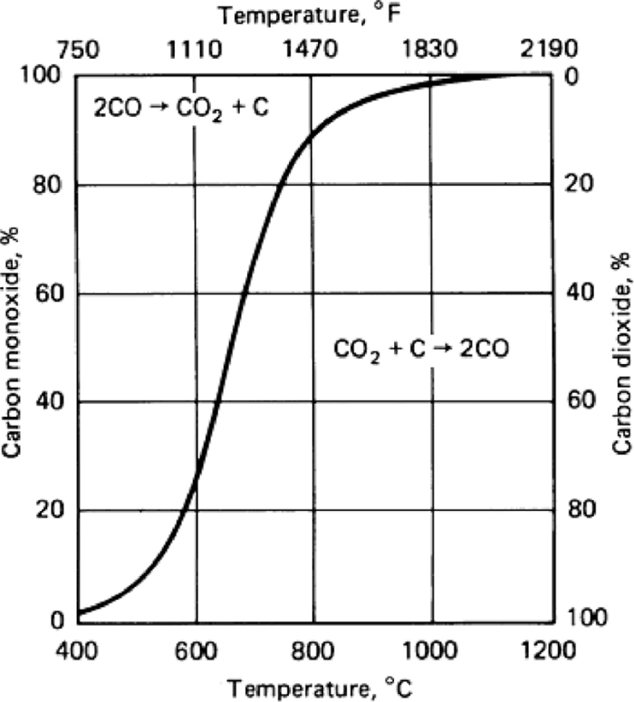
Figure 3 represents the hardness profiles as a function of distance from edge at various carburizing time and in the different amounts of the energizer material. Figure 3 illustrates:
1- In most conditions, hardness decreases with the increase of distance from the surface, because the carbon content of surface region is more than the core region of steel in the end of carburizing time. In following when the specimen quenched in oil, the microstructure of surface region contains martensite more than the core regions which contains more equilibrium phases. Figure 4 shows the formation of martensite in the edge zone of steel carburized for 5 hrs in the pack having 5 wt.% energizer. But in condition with 10 wt.% energizer (at 12 hours) and 15 wt.% energizer (for all carburizing times), by increasing the distance from the surface, at first, the hardness increases and then decreases.
2- There was not a great difference between the curves of 0 & 5 wt.% energizer materials. Therefore, it can be concluded that adding energizer material up to 5 wt.% will exert a negligible effect on the case depth.
3- At all the carburizing times, the case depth at the position of 10 wt.% of energizer were higher than the other positions (even for the 15 wt.% energizer position).
In order to better compare the results, the amounts of case depths extracted from Fig. 3 that are shown in Table 2. Using the data from Table 2, we can plot the case depth versus the amounts of energizer material for different carburizing times (Fig. 5). Figure 5 illustrates:
Table 2. The amounts of case depths at different energizer material contents and different times.
| Carburizing time (h) | Case depth (mm) versus weight percent of energizer material |
|---|
| 0 | 5 | 10 | 15 |
|---|
| 3 | 0.14 | 0.18 | 0.65 | 0.47 |
| 5 | 0.19 | 0.24 | 0.76 | 0.57 |
| 8 | 0.25 | 0.32 | 0.80 | 0.64 |
| 12 | 0.32 | 0.42 | 0.89 | 0.74 |
1- According to Fig. 5, by increasing the amount of energizer material up to about 5 wt.%, the case depth does not change greatly for all times. Another reason for the above phenomenon is the hardness-distance curves of Fig. 3 for 0 and 5 wt.% energizer, which shows a little difference.
2- For all of carburizing times, by increasing energizer material up to 11%, the carburizing phenomenon happens and case depth increases. In fact, up to 11%, the energizer material decomposes continuously and according to reaction 4, the pressure of CO2 in the carburizing pack increases continuously. The produced CO2 gas reacts with the carbon atoms within the pack according to reaction 2 and CO gas is produced. CO gas causes carburizing phenomenon on the surface of steel. In other words, up to 11%, the pressure ratio of CO to CO2 in the carburizing box is more than the equilibrium ratio of CO to CO2. If the amount of energizer material exceeds 11%, decarburizing phenomenon happens and the case depth decreases. In this situation, more sodium carbonate is decomposed, and more CO2 gas is produced. A small amount of CO2 gas enters reaction 2 and produces CO gas, and a tremendous part of this gas causes oxidation in the box environment. As a result, CO2 gas attracts atomic carbon from the surface of steel according to reaction 5.
This means the maximum case depth is obtained at about 11% of energizer material especially at the time equal to 12 hours. In other words, at this time, the maximum rate of carburizing phenomenon happens. By quenching this specimen in oil, maximum retained austenite is formed in the microstructure. Figure 6 indicates the surface microstructure of steel carburized for 12 hrs in the presence of 10 wt.% of energizer material. This figure reveals that the microstructure consists of martensite and retained austenite. At this situation, more carbon atoms diffuses into the surface of steel, so in outer layer are formed austenite having more carbon content at elevate temperature. After quenching the sample in oil, the retained austenite are formed interior the martensite packets. The presence of retained austenite indicates that the carbon content in the surface of steel was greater than 0.65%, since it has been reported1,2) that the Mf for the austenite having the high carbon content is below the room temperature. The formation of austenite caused by increasing the distance from the surface, at first, the hardness increased and then decreased, because the hardness of austenite is less than martensite.
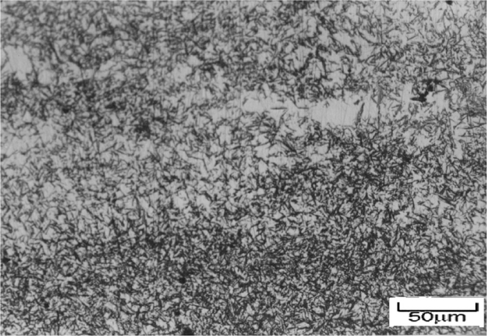
Figure 7 shows the decarburization depth of different samples carburized in packs containing 15% Na2CO3 at various carburizing times. In these figures, the brighter zone indicates the decarburized region. It is evident that increasing the time has a slight influence on the decarburized thickness.
It can be plotted the relation between the case depths vs. carburizing time for different amounts of energizer material (Fig. 8). From this figure, the following results are deductible:
1- For different amounts of energizer material, by increasing the carburizing time, the case depth increases. But the increasing slope of the case depth is high for the first 3–4 hrs. By increasing the time beyond 3–4 hrs, the increasing slope of case depth decreases. The reason for this phenomenon is that, at initial times, more carbon atoms enter the carburizing process, and the increasing rate of carbon diffusion is high, but for more carburizing times, less carbon atoms remain in the pack, and the increasing rate of carbon diffusion is low.
2- For every carburizing time, the amount of case depth for the specimens carburized in the pack with 15% energizer material is lower than the case depth of the specimens carburized in the pack with 10% energizer material. This refers to the decarburizing phenomenon in the pack having 15% energizer material.
4. Conclusions
(1) By increasing the Na2CO3 content up to about 5 wt.%, case depth for all carburizing times does not change greatly; however, for more amounts of energizer material, this affect is sizeable.
(2) At the constant time, by increasing the Na2CO3 content from 5 to 11 wt.%, the case depth increases due to carburizing phenomenon and afterwards decreases due to decarburizing phenomenon.
(3) The maximum case depth is obtained using 11 wt.% energizer material for the carburizing time of 12 hours. Also, in this situation the most volume fraction of austenite forms in outer layer of the steel.
(4) By increasing the carburizing time, the case depth increases. But, at first, the increasing rate of case depth is high. By increasing the carburizing time further, the increasing rate of case depth decreases.
(5) The microstructural evolutions of carburized specimens indicated the decreasing of surface hardness in the presence of energizer material is due to the decarburization phenomenon or the formation of retained austenite in the surface region of the steel.
(6) The formation of retained austenite causes to the increase in the case depth; however, the carburization phenomenon causes to decrease in the case depth.
(7) Results showed by using of energizer material may occur the decarburization phenomenon in the carburizing box.
References
- 1) S. R. Elmi Hosseini: J. Iron Steel Res. Int., 19 (2012), Issue 11, 76.
- 2) ASM Metals Handbook, Vol. 4, ASM International, Ohio, (1991), 363.
- 3) T. M. Loganathan, J. Purbolaksono, J. I. Inayat-Hussain and N. Wahab: Mater. Design, 32 (2011), 3544.
- 4) S. R. Elmi Hosseini and H. Khosravi: MJME, 3 (2009), Issue 3, 51 (In Persian).
- 5) S. R. Elmi Hosseini, H. Khosravi and E. Ghaderi: MJME, 3, (2009), Issue 4, 49 (In Persian).
- 6) S. R. Elmi Hosseini, E. Tohidlu and M. Shafiee: 4th National Symp. Heat Treatment, Islamic Azad University of Majlesi, Isfahan, Iran, (2009), 45 (In Persian).
- 7) C. Wick and R. F. Vielleux: Tool and Manufacturing Engineers Handbook, Vol. 3, Society of Manufacturing Engineers, Dearborn, (1999), 1985.
- 8) M. Erdogan and S. Tekeli: Mater. Charact., 49 (2003), 445.
- 9) Z. X. Yuan, Z. S. Yu, P. Tan and S. H. Song: Mater. Sci. Eng. A, 267 (1999), 162.
- 10) O. Asi, A. Cetin Can, J. Pineault and M. Belassel: Surf. Coat. Technol., 201 (2007), 5979.
- 11) A. Gulyaev: Phys. Metall., 1 (1980), 313.
- 12) D. U. I. Ogo, A. O. Ette and A. I. Iyorchir: ISIJ Int., 35 (1995), No. 2, 197.
- 13) D. U. I. Ogo, T. Ause and E. J. Ibanga: ISIJ Int., 44 (2004), No. 5, 865.
- 14) H. Jimenez, M. H. Staia and E. S. Puchi: Surf. Coat. Technol., 120 (1999), 358.
- 15) S. R. Elmi Hosseini: Int. Conf. on Materials Heat Treatment, Islamic Azad University of Majlesi, Isfahan, Iran, (2010), 21 (In Persian).
- 16) S. R. Elmi Hosseini: Int. Conf. on Materials Heat Treatment, Islamic Azad University of Majlesi, Isfahan, Iran, (2010), 16 (In Persian).
- 17) S. R. Elmi Hosseini and H. Khosravi: Int. Conf. on Materials Heat Treatment, Islamic Azad University of Majlesi, Isfahan, Iran, (2010), 30 (In Persian).
- 18) S. R. Elmi Hosseini, H. Fotuhi, G. Rudini, S. A. Hoseini Khorasani and H. Beigi: 2nd Int. Conf. on Materials Heat Treatment, Isfahan, Iran, (2011), 44 (In Persian).
- 19) S. R. Elmi Hosseini: 12th National Conf. of Surface Engineering, Isfahan, Iran, (2011), 22 (In Persian).


