Regular Article
Influence of Unstable Non-equilibrium Liquid Iron Oxide on Clustering of Alumina Particles in Steel
2013 Volume 53 Issue 4 Pages 639-647
Details
2013 Volume 53 Issue 4 Pages 639-647
Alumina clusters extracted from molten steel and from a cast slab at our plant were analyzed by SEM and TEM. It was found that a small amount of liquid FeO could accelerate the clustering of alumina inclusions in aluminum-killed steel because of the strong liquid-capillary negative pressure of liquid FeO. The sources of the FeO are most likely oxygen contamination from ferroalloy additives, residual steel adhering to the refractory surfaces of ladles and vessels, and air entrainment.
As the production of clean steel is of utmost importance to steelmakers, significant effort has been made to improve the secondary refining and casting processes. Basic knowledge about the thermodynamics of deoxidation, chemical engineering for oxygen removal, and electromagnetic processing in conjunction with fluid dynamics, has become highly sophisticated1) and has strongly enhanced the practical use of ladle furnaces, degassing equipment in the secondary refining process, well-designed tundishes, and electromagnetic stirrers and brakes in continuous casting processes. Moreover, better methods for detecting inclusions help to ensure the cleanliness of steel products.2) To optimize these processes, computer simulations concerning the evolution and removal behavior of alumina inclusions in molten steel are of great assistance,3,4,5,6,7,8,9,10,11,12,13) as is basic research about the nucleation and growth of deoxidation products.14,15,16,17,18,19,20,21,22,23) The coagulation coefficient of alumina particles strongly affects the collision growth rate of alumina clusters larger than 1 μm; however, as the reported values for the coefficient vary widely between 0.03 and 0.7,3,4,5,6,7,8,9,10,11,12,13) it is still difficult to interpret the experimental results, although the Brownian motion, the van der Waals force and other forces related to fluid dynamics were taken into consideration. We think that the coagulation behavior must also depend on the liquid-capillary force of a very small amount of liquid iron oxide bridging the solid alumina particles and working as a “binder” because of its good wettability, in addition to the abovementioned forces. Herein, we discuss changes in the morphology of alumina clusters over time and the influence of unstable non-equilibrium liquid iron oxide on the inclusion morphology, on the basis of observations of alumina clusters in molten steel in ladles and continuously cast slabs.
Two samples of interstitial-free (IF) steel (1 kg) were prepared. One was taken at the end of the RH-degassing process from molten steel in a ladle of a capacity 270 t, and the other was one-quarter the thickness of a continuously cast slab. The chemical composition was 0.001 mass%C–0.01 mass%Si–0.3 mass%Mn–0.015 mass%Ti–0.015 mass%Nb– 0.03 mass%Al. The alumina clusters were analyzed by the following methods: (i) SEM observations of the clusters extracted by an ordinary slime method,24,25) and these clusters were larger than 20 μm in diameter; (ii) SEM observations of the clusters that were collected on the surface of the steel samples (90 g) via a cold crucible remelting process,26) in which the samples were heated to 1550°C for 5 min under an Ar–2 vol%H2 gas mixture and then quenched by shutting down the power supply, and these clusters were smaller than 20 μm in diameter; and (iii) TEM observations of the cross-section of these clusters after slicing using a focused Ga-ion beam sectioning method (FIB).27) These methods for steel sampling, alumina extraction, and observation are shown as Case I-Case VI in Table 1. For these analyses, the following equipment was used: JEOL JSM-7001F(FE-SEM, 20 kV), Hitachi HF-2000(FE-TEM, 200 kV), and Hitachi FB-2000A(FIB).
| Case | Sampling | Alumina extraction | Observed size | Observed area | Apparatus |
|---|---|---|---|---|---|
| I | Molten steel | Slime | >20 μm | Outer Surface | SEM |
| II | Cast slab | Slime | >20 μm | Outer Surface | SEM |
| III | Molten steel | Cold crucible remelting | <20 μm | Outer Surface | SEM |
| IV | Cast slab | Cold crucible remelting | <20 μm | Outer Surface | SEM |
| V | Molten steel | Slime | >20 μm | Cross section | TEM |
| VI | Cast slab | Slime | >20 μm | Cross section | TEM |
The SEM images and line-scanned X-ray intensities of the alumina clusters extracted from the molten steel (Case I) and the cast slab (Case II) are shown in Figs. 1 and 2, respectively. The alumina clusters in the molten steel were composed of 0.2- to 3-μm-diameter non-faceted particles of alumina like spheres, rods, or dendrites, and these particles were bridged with iron oxide wetting at many locations (see arrows 1 and 2 in Fig. 1). Alumina clusters wrapped with iron oxide were also found in some locations. As the appearance of the iron oxide shows that it is in liquid form in molten steel, the iron oxide is most likely FeO, which has a melting point(1371°C)35) lower than that of steel. The average concentration of FeO in the clusters determined by EDX was 7 mass% in the 50×50 μm2 area of the cluster shown in Fig. 1(a).

SEM images and line analyses of alumina clusters extracted from molten steel using a slime method (Case I); images (b)–(e) are enlargements of the center part of (a); graphs (d2)–(d5) and (e2)–(e5) are profiles of X-ray intensity, I, taken at lines A-A′ in (d1) and line B-B′ in (e1), respectively; X represents the distance from A toward A′ or from B toward B′; Fe peaks were distinctly found between the alumina particles (See arrows ↓ in (d2)-(d5) and (e2)–(e5)).

SEM images and line analyses of alumina clusters extracted from a cast slab using a slime method (Case II); images (b)–(e) are enlargements of the center part of (a); graphs (d2)–(d5) and (e2)–(e5) are profiles of X-ray intensity, I, taken at lines A-A′ in (d1) and line B-B′ in (e1), respectively; X represents the distance from A toward A′ or from B toward B′; no Fe peaks were found between the alumina particles (See arrows ↓ in (d2)–(d5) and (e2)–(e5)).
The alumina clusters in the cast slab were composed of rather angular and faceted alumina particles of 1–15 μm in diameter with no iron oxide bridging the particles (see arrows 1 and 2 in Fig. 2). Many of them were tightly sintered, and it is interesting that the terraces and ledges of the facet planes of α-alumina were observed at many locations. The average concentration of FeO in these clusters determined by EDX was below the limit of detection, i.e., <0.2 mass%.
Such X-ray line analysis was performed for 20 alumina clusters in each case. The peak values of Fe intensity measured in these cases are shown in Fig. 3. It was confirmed that the Fe peak intensities of the alumina clusters extracted from the molten steel were clearly higher than those extracted from the cast slab, which were almost the same level as those of flat-plate pure alumina with a composition of 99.6 mass%Al2O3–0.1 mass%SiO2 (SSA-S produced by Nikkato Corp.).

Peak values of IFe observed by X-ray line analyses for alumina clusters extracted from the molten steel (Case I) and the cast slab (Case II); the number of measurements was 20 in each case; the pure alumina sample was a flat plate with a composition of 99.6 mass%Al2O3–mass0.1%SiO2.
The SEM images of the alumina clusters extracted from the molten steel (Case III) and the cast slab (Case IV) using the cold crucible remelting method are shown in Fig. 4. The alumina clusters in the molten steel were composed of 0.1- to 3-μm-diameter non-faceted particles of alumina bridged with a very small amount of FeO wetting in-between the alumina particles in many locations (Case III). As the alumina particles were well fixed on the steel samples quenched after the cold crucible remelting, FeO bridging with such a thin neck could be observed. The average concentration of FeO in the clusters was found to be 4–8 mass%, by measuring the clusters using EDX at the area where the steel sample surface was covered enough with the alumina particles, in order to avoid counting the intensity of the Fe X-ray emitted from the steel matrix.
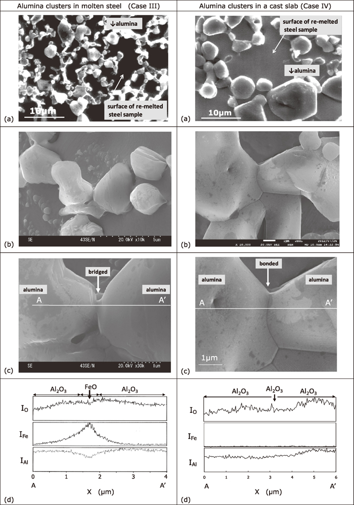
SEM images and line analyses of the alumina clusters extracted from molten steel and a cast slab through the use of a cold crucible remelting method; images (b) and (c) are enlargements of (a); graphs (d) are X-ray intensity profiles taken at line A-A′ in (c); X represents the distance from A toward A′; Fe peaks were found between the alumina particles in the molten steel (Case III), whereas no peaks were found in the cast slab (Case IV); see arrows↓in (d).
The alumina clusters in the cast slab were composed of rather angular alumina particles 1–15 μm in diameter with no iron oxide bridging the particles (Case IV). Many of them were tightly sintered, and terraces and ledges of the facet planes of the alumina were also observed at many locations. The average concentration of FeO in these clusters was below the limit of detection, i.e., <0.2 mass%. These observations are similar to the abovementioned results using the slime method.
3.3. Inner Structure of Alumina ClustersThe TEM images of the cross-sections of the alumina clusters extracted from the molten steel and from the cast slab by the slime method are shown in Fig. 5 (Case V and Case VI). FIB sectioning locations are indicated by white lines A-A′ and B-B′ on the corresponding SEM images of the outer surface. Most of the alumina clusters in the molten steel were too fragile to be sectioned using FIB. As an alternative, therefore, more thickly bonded clusters were selected as observation samples from molten steel. It was found from the cross-sectional TEM observations that the alumina clusters in the molten steel were composed of multi-crystalline alumina particles of 1–2 μm in grain size, and many small metallic iron particles 10–500 nm in diameter were detected, particularly at the grain boundaries (Case V). Considering the appearance observed with SEM as mentioned before, it was deduced that the iron particles were created by the reduction of FeO, which originally adhered to the alumina particles, with dissolved aluminum in the molten steel surrounding the alumina clusters.

SEM images of the surface of alumina clusters and TEM images of their cross sections taken along lines A-A′ and B-B′ in (a); images (c) are enlargements of (b); many metallic iron particles were found at the alumina grain boundaries and also on the inside of the grains in the molten steel (Case V); on the other hand, no such metallic iron particles were found in the alumina clusters in the cast slab (Case VI).
In the alumina clusters from the cast slab, on the other hand, multi-crystalline alumina with a grain size of 5–10 μm, which grew during casting, was observed, but no metallic iron particles were detected inside these samples (Case VI). On the basis of the observation shown in Chapter 3.1 and Chapter 3.2, the characteristics of the alumina clusters before and after casting were summarized in Table 2.
| Sampling | Individual alumina particle size (μm) | Surface morphology | Neck diameter (μm) | Neck materials | Case |
|---|---|---|---|---|---|
| Molten steel | 0.1 – 4 | Non-faceted | 0.1 – 3 | FeO, Fe*, Al2O3 | I, III, V |
| Cast slab | 1 – 15 | Faceted | 1 – 8 | Al2O3 | II, IV, VI |
A mechanism for the formation of alumina clusters suspended in aluminum-killed molten steel was considered. Based on the above-mentioned results for the alumina clusters in the molten steel and the cast slab, a mechanism of formation for the alumina clusters was deduced as shown schematically in Fig. 6. The alumina clusters may arise through the following four steps:
| (1) |
| (2) |
| (3) |
In general, there are three kinds of attractive forces between solid particles in a stationary medium: van der Waals, Coulomb, and liquid-capillary forces.29) As the Coulomb force should be zero because the alumina particles suspended in the molten steel are electro-neutral, the van der Waals and liquid-capillary forces are discussed. To simplify the calculation, it is supposed that two neighboring particles of alumina are spherical and have the same radius, as shown in Fig. 7. The calculated results are discussed here.

Schematic drawings and an explanation of the formation of the alumina clusters; they arise through four steps: (i) suspension, (ii) coagulating, (iii) sintering, and (iv) coarsening; the step (ii) was observed in Case I and III, the step (iii) was observed in Case V, and the step (iv) was observed in Case II, IV, and VI, respectively.

Schematic drawings of alumina particle attraction in molten steel by (a) van der Waals force FV and (b) liquid-capillary force FL.
The van der Waals force Fv and the pressure Pv between the two spheres of alumina (material 1) with the same radius r in the molten steel (material 2) are written as Eqs. (4) and (5).29)
| (4) |
| (5) |
Where, A121 is the Hamaker constant between the two spheres of alumina in the molten steel, and z is the distance between the spheres including their surface roughness at the atomic scale.30) A121 can be written using Eq. (6).31)
| (6) |
Where, A11 and A22 are the Hamaker constants in a vacuum for alumina and steel, respectively. Inserting the reported values of A11 = 15.5×10⁻²⁰ J and A22 = 21.2×10⁻²⁰ J32) to Eq. (6), we can obtain A121 = 0.45×10⁻²⁰ J. The value of z is assumed to be 1–10 nm, which almost corresponds to the 1–10 layers of the (0001) plane of α-alumina. Under these conditions, the values of Fv = 1×10–12 – 1×10⁻⁹ N and Pv = 1×10⁻⁷ – 1×10⁻⁴ atm were evaluated as shown in Fig. 8 (see the solid lines). It can be seen that the van der Waals force is at most the same order as the buoyancy force for the alumina particles in the molten steel when r = 10 μ m (see also the dashed lines in Fig. 8).

Attractive forces between alumina particles in molten steel and their buoyancy forces; the calculated forces and the corresponding pressures are shown in (a) and (b), respectively.
The liquid-capillary force FL and the pressure PL caused by FeO wetting between the alumina particles are represented by the Young-Laplace equations of Eqs. (7) and (8).29)
| (7) |
| (8) |
Where, σ is the surface tension between FeO and molten steel (250 mN/m28)), and r1 and r2 are the principal radii of the FeO. r1 is the so-called “negative neck radius”.
According to the value of r1 = 0.1–0.5 μm and the relation of r2 = r / 2 observed from the SEM images of Case I in Fig. 1 and Case III in Fig. 4, the values of FL = 1×10⁻⁶ – 1×10⁻³ N and PL = 2–20 atm were evaluated at the range of r = 1–10 μm, as shown in Fig. 8 (see the bold curves). Consequently, if the alumina particles are wetted by a minor amount of FeO, they will be immediately attracted whenever they collide with other alumina particles because of the 2–20 atm of negative pressure caused by the FeO bridging the alumina particles. The absolute value of the negative pressure is much higher than not only the above-mentioned van der Waals one but also the static and dynamic pressures in molten steel under ordinary operation. Therefore, it is quite conceivable that FeO can strongly accelerate the formation of alumina clusters in aluminum-killed molten steel, and the degree of acceleration depends on the amount of FeO suspended in the melt.
The coagulation of solid inclusions accelerated by liquid inclusions in molten steel has already been reported in various cases, for example, in the case of silicon-killed steel containing solid silica inclusions with liquid manganese-silicate oxide,5,12,14,17,18) in the case of aluminum-killed steels containing solid alumina inclusions with liquid exogeneous inclusions of entrained molten slag in an actual plant,33) and with liquid FeO in a laboratory experiment.34) The present results agree with these previous reports on the observation of the accelerated coagulation of solid inclusions by liquid inclusions, but it appears only in a short period of time in the case of liquid FeO because of its chemical instability. The sources of FeO are most likely oxygen contamination from ferroalloy additives, residual steel adhering to the refractory surfaces of the ladles and vessels, and air entrainment. Consequently, it is concluded that such oxygen contamination should be prevented as much as possible to ensure steel cleanliness and product quality.
In this study, both the rate of the reduction of the FeO-bridging alumina particles by dissolved aluminum in molten steel and the migration rate of the reduced Fe particles from the inside of the alumina clusters to molten steel were not quantitatively discussed. Moreover, the effect of FeOAl2O3 was not discussed here, as this intermediate compound could create no liquid-capillary force between the alumina particles in molten steel due to its high melting point of 1780°C.36) This compound might appear at the step of the sintering of alumina particles after coagulation. Further study will be needed to obtain a better understanding of these points from the viewpoint of kinetics.
On the basis of the observation of the inclusions extracted from the molten steel and from a cast slab at our plant, the formation mechanism of alumina clusters in molten steel was studied. It was found that a small amount of liquid FeO, which can have 2–20 atm of liquid-capillary negative pressure, could accelerate the clustering of alumina inclusions in aluminum-killed steel. The sources of the FeO are most likely oxygen contamination from ferroalloy additives, residual steel adhering to the refractory surfaces of the ladles and vessels, and air entrainment. It is concluded that oxygen contamination should be prevented as much as possible to ensure steel cleanliness and product quality.